How to Wire Brake Lights on a Trailer: A Comprehensive Guide

Wiring brake lights on a trailer involves connecting electrical wires to the trailer’s brake lights so that they illuminate when the towing vehicle’s brake pedal is pressed. This is important for safety as it ensures that other drivers are alerted when the trailer is slowing down or stopping. The benefits of wiring brake lights on a trailer include… Read More »

Wiring Wizardry: Mastering Minn Kota Trolling Motor Electrical Systems

A wiring diagram for a Minn Kota trolling motor is a schematic that illustrates the electrical connections between the motor’s components, including the battery, motor, controller, and wiring. It provides a detailed guide for installing and troubleshooting the motor’s electrical system. Wiring diagrams are essential for ensuring the correct functionality and safety of a trolling motor electrical system.… Read More »

Wiring Mastery: Unveiling the Basics of Car Battery Wiring Diagrams

A Basic Car Battery Wiring Diagram illustrates the electrical connections between the battery, electrical components, and ground in a vehicle. It serves as a roadmap for understanding the electrical system, troubleshooting issues, and performing repairs or modifications. The diagram is essential for understanding how electrical current flows through the vehicle, powering various systems such as lights, ignition, and… Read More »

Master Splice Automotive Wiring: Essential Tips for Reliable Connections

Splice automotive wiring involves connecting two or more electrical wires within a vehicle’s electrical system. It is a common practice for adding new components, repairing damaged wiring, or modifying existing electrical circuits. Splicing is crucial for maintaining a reliable electrical connection and ensuring proper functioning of electrical systems in vehicles. It offers benefits such as flexibility in wiring… Read More »

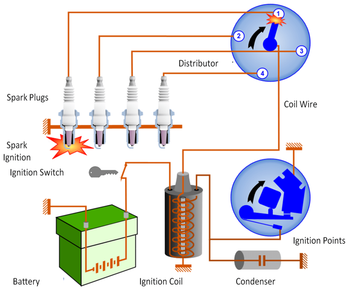
Master Ignition Systems: A Comprehensive Wiring Diagram Ignition Coil Guide

A Wiring Diagram Ignition Coil is a visual representation of the electrical connections involved in an ignition coil, a crucial component responsible for generating the high-voltage spark necessary to ignite the air-fuel mixture in an internal combustion engine. For instance, a wiring diagram for a standard 12-volt ignition coil might illustrate the connections between the coil’s positive and… Read More »

How to Master 2 Stroke CDI Wiring Diagrams: Wiring Simplified

A 2 Stroke Cdi Wiring Diagram illustrates the electrical connections between components in a two-stroke engine’s Capacitor Discharge Ignition (CDI) system, ensuring optimal spark timing and engine performance. An example would be a diagram for a 50cc moped with a single-cylinder, air-cooled engine and a CDI ignition module. Understanding these diagrams is crucial for diagnosing and repairing ignition… Read More »

Pro Guide to RJ11 Connector Wiring: Master the Art of Reliable Connections

RJ11 connector wiring refers to the arrangement of wires within an RJ11 connector, a type of telecommunication connector commonly used in telephone applications. Each wire is assigned a specific color and position, ensuring proper connectivity and signal transmission. For instance, in a standard RJ11 wiring configuration, the green wire is connected to pin 3, while the red wire… Read More »

12V Relay Wiring Simplified: A Step-by-Step Guide for Beginners

A 12v Relay Wiring Diagram 4 Pin depicts the electrical connections for a 12-volt relay with four terminals. In a vehicle, for instance, it might illustrate how to wire a relay to control the headlights, where the power source is connected to terminal 30, the load (headlights) to terminal 87, the ground to terminal 85, and the switch… Read More »