A Nest Wiring Diagram 5 Wire is a blueprint that outlines the electrical connections required for a 5-wire Nest thermostat. This diagram serves as a guide for electricians and homeowners who are installing or troubleshooting the thermostat.
The Nest Wiring Diagram 5 Wire is essential for ensuring the safe and proper functioning of the thermostat. It helps prevent electrical hazards and ensures that the thermostat accurately controls the heating and cooling system. The diagram provides clear instructions on which wires to connect to which terminals, making the installation process straightforward and efficient.
A key historical development in the world of Nest Wiring Diagrams was the introduction of digital thermostats. Digital thermostats offer greater precision and control over heating and cooling systems, leading to increased energy efficiency and savings. The Nest Wiring Diagram 5 Wire has evolved to support these advanced thermostats, ensuring seamless integration and optimal system performance.
Moving forward, this article will delve deeper into the intricacies of the Nest Wiring Diagram 5 Wire, covering its components, compatibility, and best practices for installation and troubleshooting. This comprehensive guide will empower readers with the knowledge and understanding necessary to navigate the electrical intricacies of their Nest thermostats confidently.
The Nest Wiring Diagram 5 Wire involves several essential aspects that contribute to its functionality and effectiveness. Understanding these aspects is crucial for proper installation, troubleshooting, and maintenance of the thermostat.
- Components: Terminals, wires, resistors
- Compatibility: Thermostat models, heating/cooling systems
- Installation: Wiring methods, safety precautions
- Troubleshooting: Error codes, common issues
- Maintenance: Cleaning, firmware updates
- Safety: Electrical hazards, proper handling
- Efficiency: Energy savings, system optimization
- Customization: Programmable settings, personalized schedules
- Support: Manufacturer’s resources, online forums
These aspects are interconnected and influence the overall performance of the Nest Wiring Diagram 5 Wire. For instance, proper installation ensures accurate temperature control and prevents electrical issues. Regular maintenance extends the lifespan of the thermostat and optimizes its efficiency. Understanding the compatibility aspect helps in selecting the right thermostat model for a specific heating/cooling system. By considering these aspects holistically, homeowners and technicians can ensure the reliable and effective operation of their Nest thermostats.
Components
In the context of the Nest Wiring Diagram 5 Wire, terminals, wires, and resistors play critical roles in establishing electrical connections and facilitating the flow of electricity. Terminals serve as connection points for wires, allowing the thermostat to interface with the heating/cooling system. Wires act as conduits for electrical signals and power, transmitting commands and data between the thermostat and the system components. Resistors regulate the electrical current, ensuring that the appropriate amount of power reaches the intended destination.
The precise arrangement and configuration of these components are outlined in the Nest Wiring Diagram 5 Wire. This diagram provides a roadmap for electricians and homeowners, ensuring that each wire is connected to the correct terminal and that resistors are used where necessary. Proper wiring is essential for the safe and efficient operation of the thermostat, preventing electrical hazards and ensuring accurate temperature control.
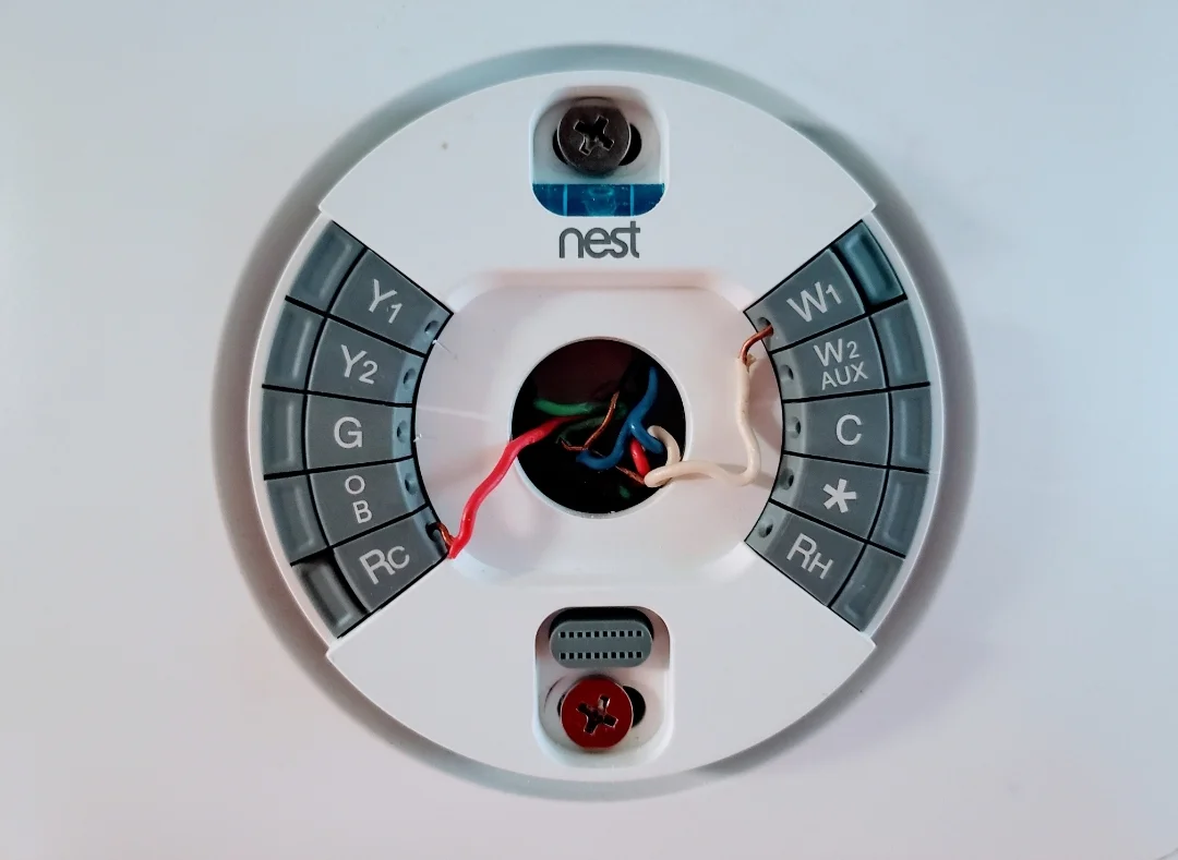
For instance, in a typical Nest Wiring Diagram 5 Wire, the red wire is connected to the “Rh” terminal, providing power to the thermostat. The white wire is connected to the “W” terminal, controlling the heating system. The green wire is connected to the “G” terminal, activating the fan. A resistor may be used in conjunction with the green wire to limit the fan’s speed. By understanding the relationship between these components and their designated terminals, technicians can troubleshoot issues and optimize the performance of the Nest thermostat.
In summary, the Nest Wiring Diagram 5 Wire relies on the proper integration of terminals, wires, and resistors to establish functional electrical connections. These components work in harmony to transmit power, regulate current, and facilitate communication between the thermostat and the heating/cooling system. A clear understanding of their roles and interactions empowers homeowners and technicians to ensure the safe, efficient, and reliable operation of their Nest thermostats.
Compatibility
In the landscape of Nest Wiring Diagram 5 Wire, compatibility stands as a cornerstone, ensuring seamless integration between Nest thermostats and diverse heating/cooling systems. Compatibility encompasses various facets, each requiring careful consideration for successful installation and operation.
- Thermostat Model Compatibility: Nest thermostats come in different models, each designed for specific capabilities and system requirements. Compatibility ensures that the chosen thermostat model aligns with the existing heating/cooling system, considering factors like voltage, wiring configuration, and supported features.
- Heating System Compatibility: Nest thermostats are compatible with various heating systems, including gas furnaces, heat pumps, boilers, and radiant floor heating. Compatibility verification involves assessing the system’s voltage, wiring configuration, and specific requirements to ensure proper operation and energy efficiency.
- Cooling System Compatibility: Compatibility extends to cooling systems such as central air conditioners and heat pumps with cooling capabilities. Factors like refrigerant type, tonnage, and electrical specifications must be considered to ensure seamless integration and optimal cooling performance.
- Electrical Compatibility: Electrical compatibility encompasses voltage, amperage, and wiring requirements. Nest thermostats are designed to operate within specific electrical parameters. Compatibility verification ensures that the existing wiring meets these requirements, preventing electrical hazards and ensuring safe and efficient operation.
Understanding and adhering to compatibility guidelines are crucial for successful Nest thermostat installation and operation. Compatibility ensures that the thermostat can effectively communicate with the heating/cooling system, accurately control temperature, and optimize energy consumption. By carefully considering the compatibility aspects outlined in the Nest Wiring Diagram 5 Wire, homeowners and technicians can achieve a seamless and efficient integration of Nest thermostats into their home’s HVAC systems.
Installation
In the realm of Nest Wiring Diagram 5 Wire, installation plays a pivotal role, demanding meticulous attention to wiring methods and safety precautions. Proper installation ensures the safe and efficient operation of the Nest thermostat, preventing electrical hazards and maximizing system performance.
The Nest Wiring Diagram 5 Wire provides a comprehensive roadmap for the installation process, outlining the specific wiring methods and safety precautions to be followed. These guidelines are crucial, as they dictate the correct connection of wires to terminals, ensuring compatibility with the heating/cooling system and preventing electrical issues. Deviating from the prescribed wiring methods can lead to incorrect temperature readings, system malfunctions, or even electrical fires.
Real-life examples underscore the importance of adhering to installation best practices. For instance, neglecting to properly connect the “C” wire (common wire) can result in power issues, causing the thermostat to lose its Wi-Fi connection or reset its settings. Similarly, failing to observe polarity when connecting wires can lead to incorrect operation or damage to the thermostat. By following the wiring methods and safety precautions outlined in the Nest Wiring Diagram 5 Wire, homeowners and technicians can avoid these pitfalls, ensuring a safe and successful installation.
Understanding the practical applications of correct installation extends beyond preventing immediate hazards. A properly installed Nest thermostat optimizes energy efficiency, leading to reduced utility bills. Accurate temperature control minimizes energy wastage, while features like smart scheduling and geofencing further enhance savings. Moreover, a well-installed thermostat contributes to the longevity of the HVAC system, preventing premature breakdowns and costly repairs.
In conclusion, the connection between “Installation: Wiring methods, safety precautions” and “Nest Wiring Diagram 5 Wire” is inseparable. The diagram provides the blueprint for a safe and efficient installation, guiding users through the proper wiring techniques and safety measures. By adhering to these guidelines, homeowners and technicians can ensure the optimal performance of their Nest thermostats, maximizing comfort, energy savings, and system longevity.
Troubleshooting
In the context of “Nest Wiring Diagram 5 Wire,” troubleshooting plays a vital role in diagnosing and resolving issues that may arise during installation, operation, or maintenance. The diagram provides a comprehensive framework for understanding the electrical connections and system configuration, enabling efficient troubleshooting and rectification of common problems.
Troubleshooting involves interpreting error codes and identifying their root causes. The Nest Wiring Diagram 5 Wire serves as a valuable tool in this process, as it helps technicians and homeowners pinpoint the specific component or connection responsible for the issue. For instance, an “E1” error code may indicate an open circuit in the temperature sensor, guiding the troubleshooter to inspect the wiring and connections related to that sensor.
Real-life examples further illustrate the practical significance of troubleshooting within the Nest Wiring Diagram 5 Wire. A loose connection in the “C” wire (common wire) can lead to intermittent power issues, causing the thermostat to reset or lose its Wi-Fi connection. By referring to the diagram and following troubleshooting steps, technicians can quickly identify and address the loose connection, restoring proper thermostat functionality.
Understanding the relationship between troubleshooting and the Nest Wiring Diagram 5 Wire empowers homeowners and technicians to maintain optimal system performance. Proactively addressing error codes and common issues prevents minor problems from escalating into costly repairs or system failures. Regular maintenance and troubleshooting also enhance the longevity of the HVAC system, maximizing its efficiency and lifespan.
Maintenance
In the realm of “Nest Wiring Diagram 5 Wire,” maintenance plays a crucial role in ensuring the long-term functionality, efficiency, and reliability of the thermostat. This maintenance encompasses two key aspects: cleaning and firmware updates.
Regular cleaning of the Nest thermostat, including its sensors and terminals, is essential for maintaining optimal performance. Dust, dirt, and debris can accumulate over time, potentially interfering with the thermostat’s ability to accurately detect temperature and humidity levels. Cleaning the thermostat as per the manufacturer’s guidelines helps prevent these issues, ensuring precise temperature control and efficient operation of the HVAC system.
Firmware updates, on the other hand, address software-related issues and introduce new features to the Nest thermostat. These updates are released periodically by Nest and can be easily installed through the thermostat’s user interface or mobile app. Firmware updates often include bug fixes, performance improvements, and compatibility enhancements, ensuring that the thermostat remains up-to-date with the latest technological advancements and security patches.
The connection between “Maintenance: Cleaning, firmware updates” and “Nest Wiring Diagram 5 Wire” lies in the fact that proper maintenance practices contribute to the long-term integrity and reliability of the wiring connections. A clean thermostat, free from dust and debris, minimizes the risk of electrical problems and ensures that the electrical signals transmitted through the wiring are accurate and uninterrupted. Regular firmware updates address potential software glitches or security vulnerabilities that could affect the thermostat’s ability to communicate effectively with the HVAC system via the wiring.
In summary, the relationship between “Maintenance: Cleaning, firmware updates” and “Nest Wiring Diagram 5 Wire” is crucial for maintaining the optimal performance and longevity of the thermostat. By adhering to regular cleaning and firmware update schedules, homeowners can proactively prevent issues, minimize the need for repairs, and ensure the continued efficient operation of their HVAC systems.
Safety
In the context of “Nest Wiring Diagram 5 Wire,” safety plays a paramount role, emphasizing the importance of understanding and adhering to proper electrical handling practices. The diagram serves as a roadmap for the installation and maintenance of the thermostat, highlighting the critical measures necessary to prevent electrical hazards and ensure safe operation.
Electrical hazards, if not properly addressed, can have serious consequences, ranging from minor shocks to severe burns or even electrical fires. The Nest Wiring Diagram 5 Wire provides detailed instructions and warnings regarding the handling of electrical wires, terminals, and components, guiding users through the process safely and effectively. Understanding the potential risks and following the safety guidelines outlined in the diagram is essential for preventing electrical accidents and protecting both the user and the thermostat.
Real-life examples further underscore the significance of safety considerations within the Nest Wiring Diagram 5 Wire. For instance, failing to properly insulate exposed wires or neglecting to turn off the power supply before working on the thermostat can lead to electrical shocks or short circuits. Conversely, adhering to the safety guidelines and using appropriate tools and equipment minimizes the risks associated with electrical work, ensuring a safe and successful installation or maintenance process.
The practical applications of understanding the connection between “Safety: Electrical hazards, proper handling” and “Nest Wiring Diagram 5 Wire” extend beyond immediate hazard prevention. By prioritizing safety, homeowners and technicians can contribute to the longevity and reliability of the thermostat and the HVAC system as a whole. Safe handling practices minimize the likelihood of damage to components or wiring, reducing the need for costly repairs and replacements. Moreover, a well-maintained and safely installed thermostat optimizes system performance, leading to increased energy efficiency and reduced utility bills.
In summary, the “Nest Wiring Diagram 5 Wire” places a strong emphasis on safety, providing clear guidelines for electrical hazard prevention. Understanding and adhering to these safety measures is crucial for ensuring a safe and successful installation and maintenance process. By prioritizing safety, homeowners and technicians can protect themselves and their property, extend the lifespan of their thermostat and HVAC system, and optimize system performance.
Efficiency
In the realm of “Nest Wiring Diagram 5 Wire,” efficiency stands as a cornerstone, influencing both energy savings and system optimization. The diagram provides a blueprint for the efficient operation of the thermostat, ensuring optimal performance and reduced energy consumption.
The connection between efficiency and the Nest Wiring Diagram 5 Wire is multifaceted. Proper wiring techniques, as outlined in the diagram, minimize energy wastage and ensure accurate temperature control. For instance, correct wiring of the “C” wire (common wire) provides a continuous power supply to the thermostat, eliminating the need for constant battery replacements and reducing energy consumption. Additionally, the diagram guides users in optimizing system settings, such as scheduling and geofencing, which further enhance energy savings.
Real-life examples illustrate the tangible benefits of efficiency within the Nest Wiring Diagram 5 Wire. Homes with properly wired and optimized Nest thermostats often experience significant reductions in their energy bills. The thermostat’s ability to learn and adapt to occupants’ heating and cooling preferences, combined with its energy-saving features, leads to a more efficient and cost-effective HVAC system.
Understanding the connection between efficiency and the Nest Wiring Diagram 5 Wire empowers homeowners and technicians to make informed decisions that maximize energy savings and system performance. By adhering to the guidelines and recommendations provided in the diagram, users can ensure that their Nest thermostats operate at peak efficiency, contributing to a more sustainable and cost-conscious home environment.
Customization
In the realm of “Nest Wiring Diagram 5 Wire,” customization plays a central role, empowering homeowners with the ability to tailor their thermostats to their unique preferences and lifestyles. The diagram provides a framework for configuring programmable settings and personalized schedules, enabling users to optimize comfort, energy efficiency, and cost savings.
Customization, through programmable settings and personalized schedules, is a critical component of the Nest Wiring Diagram 5 Wire. It allows users to create heating and cooling schedules that align with their daily routines and preferences. For instance, the thermostat can be programmed to automatically adjust the temperature when occupants are away or asleep, minimizing energy wastage. Additionally, geofencing features enable the thermostat to adjust settings based on the user’s location, further enhancing efficiency and convenience.
Real-life examples showcase the practical benefits of customization within the Nest Wiring Diagram 5 Wire. Homes with customized thermostats often experience reduced energy consumption and lower utility bills. The ability to fine-tune temperature settings and leverage geofencing capabilities leads to a more efficient and cost-effective HVAC system. Moreover, personalized schedules accommodate varying preferences within households, ensuring comfort for all occupants.
Understanding the connection between customization and the Nest Wiring Diagram 5 Wire empowers homeowners to take control of their home environment and optimize their HVAC systems. By utilizing the programmable settings and personalized schedules outlined in the diagram, users can create a comfortable and energy-efficient living space that meets their specific needs.
Support
Within the context of “Nest Wiring Diagram 5 Wire,” support plays a pivotal role in ensuring successful installation, operation, and troubleshooting of Nest thermostats. This support encompasses a comprehensive range of resources and platforms, including manufacturer’s documentation, online forums, and technical assistance.
Manufacturer’s resources, such as user manuals, installation guides, and technical support documents, provide a wealth of information and guidance for users. These resources empower homeowners and technicians with the knowledge and understanding necessary to navigate the intricacies of the Nest Wiring Diagram 5 Wire and complete the installation process confidently and efficiently. Additionally, online forums serve as vibrant communities where users can connect with peers, share experiences, and seek advice on specific issues or challenges they may encounter.
Real-life examples underscore the critical role of support within the Nest Wiring Diagram 5 Wire. For instance, a homeowner attempting to install a Nest thermostat may encounter difficulties in understanding the wiring configuration. By referring to the manufacturer’s user manual or seeking assistance on an online forum, they can quickly access clear instructions and expert advice, enabling them to complete the installation successfully. Moreover, ongoing support resources ensure that users have access to the latest firmware updates, compatibility information, and troubleshooting tips, maximizing the longevity and performance of their Nest thermostats.
Understanding the connection between support and the Nest Wiring Diagram 5 Wire empowers users to take a proactive approach to thermostat maintenance and troubleshooting. By leveraging the available resources and engaging with the supportive online community, homeowners and technicians can minimize downtime, optimize system performance, and enjoy the full benefits of their Nest thermostats.


Related Posts


