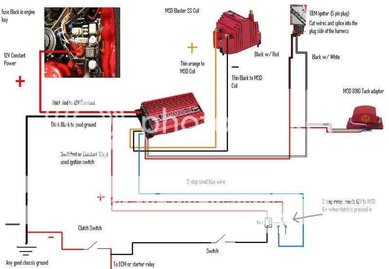
An MSD 2 Step Wiring Diagram is a schematic representation of the electrical connections required to install an MSD 2 Step ignition system in a vehicle. The diagram outlines the necessary wiring for the control box, ignition module, and other components to ensure proper operation of the ignition system.
It provides a visual guide for technicians and enthusiasts to follow during the installation process.
The diagram is crucial for achieving optimal performance and preventing potential electrical issues. By following the diagram accurately, installers can ensure that the ignition system is configured correctly to match the engine’s specific requirements. Properly installed MSD 2 Step systems can enhance engine performance, improve fuel economy, and reduce emissions.
Throughout history, ignition systems have evolved significantly to meet the demands of higher-performance engines. The MSD 2 Step Wiring Diagram represents a key development in ignition technology, enabling enthusiasts and professionals to unlock the full potential of their vehicles.
As we delve further into this article, we will explore the intricacies of MSD 2 Step Wiring Diagrams, including their various components, installation procedures, and advanced features. We will also discuss the associated benefits and real-world applications of these diagrams in the automotive industry.
MSD 2 Step Wiring Diagrams are crucial for understanding the intricate electrical connections involved in installing and operating MSD 2 Step ignition systems. These diagrams provide a visual representation of the wiring scheme, ensuring proper configuration and optimal performance.
- Components: Diagrams identify the necessary components, including the control box, ignition module, coils, and wiring harness.
- Connections: Diagrams illustrate the specific electrical connections between the components, including power, ground, and signal wires.
- Compatibility: Diagrams are specific to different MSD 2 Step models and engine types, ensuring compatibility and proper operation.
- Ignition Timing: Diagrams guide the setting of ignition timing, which is critical for engine performance and efficiency.
- Troubleshooting: Diagrams assist in diagnosing and resolving electrical issues or performance problems.
- Safety: Diagrams emphasize proper wiring techniques to prevent electrical hazards and ensure safe operation.
- Performance Optimization: By following the diagrams accurately, installers can optimize ignition timing and other settings for maximum engine performance.
- Customization: Diagrams provide a framework for customizing the ignition system to suit specific engine modifications or performance goals.
In conclusion, MSD 2 Step Wiring Diagrams are essential for the successful installation, operation, and customization of MSD 2 Step ignition systems. They provide a comprehensive guide to the electrical connections, ensuring proper functionality, optimal performance, and safety. Understanding these key aspects is crucial for enthusiasts, technicians, and anyone looking to maximize the potential of their ignition system.
Components
In an MSD 2 Step Wiring Diagram, identifying the necessary components is crucial because these components form the core of the ignition system. The diagram provides a clear understanding of how each component interacts and contributes to the overall functionality of the system.
The control box is the brain of the ignition system, responsible for managing ignition timing and controlling the spark delivery. The ignition module amplifies the control box’s signals to generate the necessary voltage for the ignition coils. The coils, in turn, create high-voltage sparks that ignite the air-fuel mixture in the engine’s cylinders. Finally, the wiring harness connects all these components, ensuring proper electrical flow and communication.
A real-life example of the importance of component identification in an MSD 2 Step Wiring Diagram is when troubleshooting ignition system issues. By referring to the diagram, technicians can quickly identify the specific component that is causing the problem, whether it’s a faulty control box, ignition module, coil, or wiring issue. This targeted approach saves time and effort in diagnosing and resolving the issue.
Practically, understanding the components of an MSD 2 Step Wiring Diagram empowers enthusiasts and technicians to customize and optimize their ignition systems. They can select appropriate components, such as higher-performance coils or ignition modules, to enhance ignition timing and spark quality, resulting in improved engine performance and efficiency.
In summary, the identification of necessary components in an MSD 2 Step Wiring Diagram is essential for understanding the system’s functionality, troubleshooting issues, and customizing the ignition system for optimal performance. This knowledge enables enthusiasts and technicians to maximize the potential of their ignition systems.
Connections
In the context of MSD 2 Step Wiring Diagrams, understanding the specific electrical connections between the components is crucial for achieving optimal system performance and preventing electrical issues. These diagrams provide a detailed roadmap for wiring the control box, ignition module, coils, and other components, ensuring proper power distribution, grounding, and signal transmission.
- Power Connections: Diagrams clearly illustrate the power connections between the control box and the ignition module, as well as the power source. These connections provide the necessary voltage and current to operate the ignition system.
- Ground Connections: Proper grounding is essential for the stability and reliability of the ignition system. Diagrams specify the grounding points for the control box, ignition module, and coils, ensuring a solid electrical connection to the vehicle’s chassis.
- Signal Connections: Signal wires transmit timing and control information between the components. Diagrams show the connections between the control box and the ignition module, as well as the tachometer and other devices that receive ignition timing data.
- Component-Specific Connections: Diagrams also provide detailed connections for specific components such as coils and ignition modules. These connections vary depending on the type of ignition system and the specific components used, and the diagrams ensure that they are wired correctly.
By accurately following the electrical connections outlined in the MSD 2 Step Wiring Diagrams, installers can ensure that the ignition system is properly configured to match the engine’s specific requirements. This attention to detail leads to optimal ignition timing, improved engine performance, and reduced emissions. Moreover, the diagrams serve as a valuable troubleshooting tool, helping technicians quickly identify and resolve any electrical issues that may arise.
Compatibility
Within the context of “MSD 2 Step Wiring Diagrams,” compatibility plays a crucial role in ensuring that the ignition system operates seamlessly with the specific engine and vehicle configuration. These diagrams are meticulously designed to match the unique electrical and performance characteristics of different MSD 2 Step models and engine types.
- Engine Compatibility: Diagrams consider the specific firing order, number of cylinders, and ignition requirements of different engines. This ensures that the ignition timing is optimized for each engine, maximizing performance and efficiency.
- MSD 2 Step Model Compatibility: Diagrams are tailored to the specific features and capabilities of different MSD 2 Step models. This includes compatibility with various ignition coils, rev limiters, and other accessories, allowing for a customized ignition system setup.
- Electrical Compatibility: Diagrams account for the electrical specifications of the ignition system components, such as voltage requirements, current draw, and signal compatibility. This ensures that all components work together harmoniously, preventing electrical issues and malfunctions.
- Real-World Examples: Compatibility considerations are crucial in practice. For instance, a diagram for a high-performance V8 engine will differ from one designed for a compact 4-cylinder engine. Proper compatibility ensures that the ignition system is tailored to the specific needs of each application.
In conclusion, compatibility is a fundamental aspect of MSD 2 Step Wiring Diagrams. By providing specific diagrams for different models and engine types, these diagrams ensure that the ignition system is optimally configured for each application. Understanding the importance of compatibility empowers enthusiasts and technicians to select the correct diagram and achieve the best possible performance from their MSD 2 Step ignition systems.
Ignition Timing
Within the context of “Msd 2 Step Wiring Diagram,” ignition timing plays a pivotal role in optimizing engine performance and efficiency. These diagrams provide precise guidance on setting the timing, ensuring that the spark plugs ignite the air-fuel mixture at the optimal moment in each cylinder’s combustion cycle.
- Precise Control of Combustion: Diagrams help determine the exact moment when the spark plugs fire, ensuring that combustion occurs at the most efficient point in the piston’s stroke. This precise control optimizes power output and reduces emissions.
- Customization for Engine Modifications: Engine modifications, such as changes to camshaft profiles or compression ratios, can alter the optimal ignition timing. Diagrams allow enthusiasts and technicians to adjust the timing accordingly, maximizing the benefits of these modifications.
- Real-Life Example: In a high-performance engine, advancing the ignition timing can improve throttle response and power, while retarding the timing can prevent engine knocking. Diagrams provide the necessary guidance to achieve these adjustments safely and effectively.
- Troubleshooting and Diagnostics: Ignition timing issues can lead to performance problems or engine damage. Diagrams assist in troubleshooting these issues by providing a visual representation of the timing settings, enabling technicians to quickly identify and correct any discrepancies.
In conclusion, ignition timing is a crucial aspect of “Msd 2 Step Wiring Diagram” that directly impacts engine performance and efficiency. By providing detailed guidance on setting the timing, these diagrams empower enthusiasts and technicians to optimize their ignition systems for various engine configurations and performance goals. Understanding the importance of ignition timing and the role of diagrams in setting it correctly is essential for maximizing the potential of any MSD 2 Step ignition system.
Troubleshooting
Within the context of “MSD 2 Step Wiring Diagrams,” troubleshooting is a crucial aspect that empowers enthusiasts and technicians to identify and resolve electrical issues or performance problems. These diagrams provide a visual representation of the ignition system’s electrical connections, making it easier to pinpoint the source of any malfunctions.
- Identifying Faulty Components: Diagrams help identify faulty components within the ignition system, such as a malfunctioning control box, ignition module, or coil. By comparing the actual wiring configuration to the diagram, technicians can quickly isolate the problematic component and replace it.
- Real-Life Example: A common issue is a no-spark condition. By referring to the wiring diagram, technicians can systematically check the power supply, ground connections, and signal wires to identify the point of failure, whether it’s a loose connection, a blown fuse, or a faulty component.
- Electrical Short Diagnosis: Diagrams assist in diagnosing electrical shorts, which can cause various problems such as blown fuses, erratic ignition timing, or even engine damage. By analyzing the wiring diagram, technicians can trace the electrical paths and locate the point of the short circuit.
- Performance Optimization: Troubleshooting diagrams can also help optimize ignition system performance. By fine-tuning the ignition timing or adjusting the rev limiter settings, technicians can improve engine response, power output, and fuel efficiency.
In conclusion, the troubleshooting aspect of “MSD 2 Step Wiring Diagrams” provides a valuable tool for diagnosing and resolving electrical issues or performance problems in ignition systems. These diagrams empower enthusiasts and technicians to identify faulty components, diagnose electrical shorts, and optimize ignition system performance, ensuring reliable operation and maximum engine efficiency.
Safety
Within the context of “MSD 2 Step Wiring Diagrams,” safety is paramount. These diagrams provide detailed instructions and guidelines on proper wiring techniques to prevent electrical hazards and ensure safe operation. By adhering to these guidelines, enthusiasts and technicians can minimize the risk of electrical fires, shorts, and other dangerous situations.
- Proper Grounding: Diagrams emphasize the importance of proper grounding to prevent electrical shorts and ensure stable system operation. Improper grounding can lead to voltage leaks, interference, and potential damage to components.
- Correct Wire Gauge: Diagrams specify the appropriate wire gauge for each connection, ensuring that wires can handle the current load without overheating or causing voltage drop. Oversized wires can be bulky and difficult to work with, while undersized wires can lead to excessive resistance and power loss.
- Protected Connections: Diagrams show how to properly insulate and protect electrical connections from moisture, heat, and vibration. Exposed or damaged connections can lead to arcing, shorts, and potential fires.
- Fuse and Circuit Protection: Diagrams indicate the location and amperage of fuses and circuit breakers, which protect the ignition system from overcurrent conditions. Proper fuse selection and placement prevent damage to components and wiring in the event of a fault.
In conclusion, the safety guidelines emphasized in “MSD 2 Step Wiring Diagrams” are crucial for preventing electrical hazards and ensuring the safe operation of ignition systems. By following these diagrams and adhering to proper wiring techniques, enthusiasts and technicians can minimize the risk of electrical issues, protect components, and ensure a reliable and efficient ignition system.
Performance Optimization
In the realm of “Msd 2 Step Wiring Diagram,” performance optimization holds a central position. These diagrams provide a detailed roadmap for configuring ignition timing and other critical settings, empowering enthusiasts and technicians to unlock the full potential of their engines. By meticulously adhering to the guidelines outlined in these diagrams, installers can achieve optimal ignition timing, maximize spark energy, and fine-tune various parameters to enhance overall engine performance.
- Precise Ignition Timing: Diagrams enable installers to set ignition timing with pinpoint accuracy, ensuring that the spark plugs ignite the air-fuel mixture at the optimal moment in the combustion cycle. This precise timing optimizes power output, improves fuel efficiency, and reduces emissions.
- Customized Spark Energy: Diagrams provide guidance on selecting the appropriate ignition coils and spark plugs, which play a crucial role in generating the spark energy necessary for efficient combustion. By matching the ignition system components to the engine’s specific needs, installers can maximize spark energy and improve engine performance.
- Rev Limiter Adjustment: Diagrams include instructions for setting the rev limiter, a safety feature that prevents the engine from over-revving. Properly adjusting the rev limiter protects the engine from damage and allows for optimal power delivery throughout the rev range.
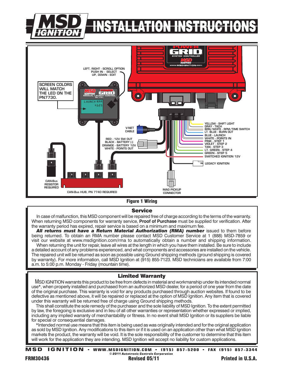
- Advanced Features: Modern MSD 2 Step Wiring Diagrams also encompass advanced features such as multi-step ignition timing, launch control, and data logging capabilities. These features provide even greater control over ignition timing and engine performance, enabling enthusiasts and racers to extract maximum power and efficiency from their engines.
In conclusion, the performance optimization aspect of “Msd 2 Step Wiring Diagram” empowers enthusiasts and technicians to maximize engine performance through precise ignition timing, customized spark energy, rev limiter adjustment, and advanced features. By following the diagrams accurately, installers can unlock the full potential of their ignition systems, leading to increased power, improved fuel economy, and enhanced overall engine performance.
Customization
Within the realm of “Msd 2 Step Wiring Diagram,” customization plays a pivotal role in empowering enthusiasts and technicians to tailor their ignition systems to meet specific engine modifications or performance goals. These diagrams provide a flexible framework that allows for a range of adjustments and modifications, unlocking the full potential of the ignition system and the engine itself.
- Ignition Timing Advance/Retard: Diagrams enable precise adjustment of ignition timing, allowing for optimization based on engine modifications such as camshaft profiles or compression ratios. This customization optimizes combustion timing, maximizing power output and efficiency.
- Coil Selection: Diagrams provide guidance on selecting the appropriate ignition coils based on engine requirements and performance goals. Upgrading to high-performance coils can deliver increased spark energy, enhancing ignition reliability and improving engine responsiveness.
- Rev Limiter Settings: Diagrams include instructions for adjusting the rev limiter, a safety feature that prevents engine over-revving. Customizing the rev limiter allows for fine-tuning the engine’s operating range, optimizing power delivery and protecting against potential damage.
- Multi-Step Ignition: Advanced diagrams encompass multi-step ignition timing, enabling precise control over ignition timing at different RPM ranges. This customization optimizes combustion efficiency and power output throughout the engine’s operating range.
In conclusion, the customization aspect of “Msd 2 Step Wiring Diagram” empowers enthusiasts and technicians to tailor their ignition systems to suit specific engine modifications or performance goals. By providing a flexible framework for adjusting ignition timing, selecting appropriate coils, customizing rev limiters, and implementing advanced features, these diagrams unlock the full potential of the ignition system, leading to enhanced engine performance, efficiency, and reliability.


Related Posts


