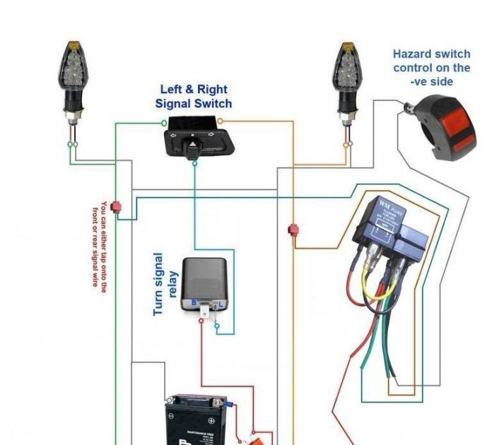
A Motorcycle Turn Signal Wiring Diagram visually depicts the electrical connections required for the proper functioning of turn signals on a motorcycle. It specifies the wiring scheme, wire gauge, connectors, fuses, and other electrical components, providing a blueprint for installation and repair.
The turn signal wiring diagram ensures proper connection between the turn signal switch, flasher unit, indicator lights, and power source, enabling the rider to communicate their intended direction change to other road users. It helps prevent electrical faults, ensures optimal signal visibility, and enhances overall motorcycle safety.
Historically, the introduction of electronic flasher units in the 1960s significantly improved turn signal reliability and operation. Today’s wiring diagrams incorporate modern components and technologies, catering to the advancements in motorcycle electrical systems.
Understanding the essential aspects of a Motorcycle Turn Signal Wiring Diagram is crucial for ensuring the proper installation, maintenance, and troubleshooting of turn signals on a motorcycle. These aspects encompass various dimensions, each playing a vital role in the effective functioning of the turn signal system.
- Components: Turn signal wiring diagrams detail the electrical components involved, including the turn signal switch, flasher unit, indicator lights, and power source.
- Wiring Scheme: The diagram outlines the specific wiring scheme, specifying the connections between components and the flow of electrical current.
- Wire Gauge: It specifies the appropriate wire gauge for each connection, ensuring proper current carrying capacity and minimizing voltage drop.
- Connectors: The diagram identifies the types of connectors used, such as bullet connectors, spade terminals, or weatherproof connectors, ensuring secure and reliable electrical connections.
- Fuses: Fuses protect the electrical circuit from overcurrent conditions, preventing damage to components. The diagram indicates the location and amperage of fuses.
- Grounding: Proper grounding is essential for the turn signal system to function correctly. The diagram shows the grounding points and the appropriate gauge of wire for grounding connections.
- Troubleshooting: The diagram assists in troubleshooting turn signal malfunctions by providing a visual representation of the electrical connections, making it easier to identify potential issues.
- Customization: For custom motorcycle builds or modifications, the wiring diagram serves as a guide for adapting the turn signal system to specific requirements.
These aspects collectively provide a comprehensive understanding of the Motorcycle Turn Signal Wiring Diagram, enabling proper installation, maintenance, and troubleshooting, ensuring reliable and efficient turn signal operation, which is critical for motorcycle safety and communication on the road.
Components: Turn signal wiring diagrams detail the electrical components involved, including the turn signal switch, flasher unit, indicator lights, and power source.
Within the Motorcycle Turn Signal Wiring Diagram, the electrical components play a critical role in ensuring the proper functioning of turn signals. These components include the turn signal switch, flasher unit, indicator lights, and power source, each with its specific function and characteristics.
- Turn Signal Switch: The turn signal switch is the primary control for activating the turn signals. It allows the rider to select the desired turn direction (left or right) and initiate the flashing sequence.
- Flasher Unit: The flasher unit regulates the flashing rate of the turn signals. It generates a pulsating electrical signal that causes the indicator lights to flash alternately.
- Indicator Lights: The indicator lights, also known as turn signals or blinkers, are the visible indicators of the rider’s intended turn direction. They flash when activated by the turn signal switch.
- Power Source: The power source, typically the motorcycle’s battery, provides the electrical power for the turn signal system. It supplies the necessary voltage and current to operate the electrical components.
These components work in conjunction to create a reliable and effective turn signal system, enabling the rider to communicate their intentions to other road users and enhancing overall motorcycle safety.
Wiring Scheme: The diagram outlines the specific wiring scheme, specifying the connections between components and the flow of electrical current.
Within the context of a Motorcycle Turn Signal Wiring Diagram, the wiring scheme is a critical component that determines the proper functioning and reliability of the turn signal system. It outlines the specific electrical connections between the turn signal switch, flasher unit, indicator lights, and power source, ensuring that electrical current flows through the system in the intended manner.
Without a well-defined wiring scheme, the turn signals may not function correctly, leading to safety hazards and communication issues on the road. For instance, incorrect wiring can result in turn signals that do not flash alternately, remain constantly lit, or fail to illuminate altogether.
Real-life examples of wiring schemes in Motorcycle Turn Signal Wiring Diagrams include color-coded wires, terminal numbers, and specific connector types. These elements provide a structured and standardized approach to electrical connections, simplifying installation, maintenance, and troubleshooting.
Understanding the wiring scheme is essential for both professional motorcycle technicians and DIY enthusiasts. It enables them to trace electrical faults, modify turn signal systems, and customize the wiring to suit specific motorcycle models or custom builds.
Wire Gauge: It specifies the appropriate wire gauge for each connection, ensuring proper current carrying capacity and minimizing voltage drop.
The appropriate wire gauge in a Motorcycle Turn Signal Wiring Diagram serves as the electrical backbone, ensuring efficient current flow and minimizing voltage loss. Improper wire gauge selection can result in inadequate current carrying capacity, leading to voltage drop, dim turn signal illumination, and potential overheating or electrical faults.
For instance, if the wire gauge is too small, it may not be able to handle the current demand of the turn signal system, causing voltage drop and reduced light output. Conversely, an excessively large wire gauge may be unnecessary and add unnecessary weight to the motorcycle’s electrical system.
In real-life applications, wire gauges are standardized according to the American Wire Gauge (AWG) system. Thicker wires have lower AWG numbers, indicating their ability to carry higher currents. For motorcycle turn signals, common wire gauges range from 16 AWG to 14 AWG, depending on the specific application and power requirements.
Understanding the principles behind wire gauge selection enables informed decision-making when installing or modifying motorcycle turn signal systems. It ensures that the electrical system operates within its intended parameters, preventing potential hazards and maximizing the effectiveness and reliability of the turn signals.
Connectors: The diagram identifies the types of connectors used, such as bullet connectors, spade terminals, or weatherproof connectors, ensuring secure and reliable electrical connections.
Within the Motorcycle Turn Signal Wiring Diagram, connectors play a crucial role in establishing and maintaining secure electrical connections between the various components of the turn signal system. These connectors ensure the proper flow of electrical current, preventing intermittent faults and ensuring reliable turn signal operation.
- Types of Connectors: The diagram specifies the types of connectors used in the turn signal system, which may include bullet connectors, spade terminals, weatherproof connectors, or other specialized connectors. Each type of connector is designed for specific applications, ensuring a secure and appropriate connection.
- Connection Methods: The diagram illustrates the proper connection methods for each type of connector. This includes details on wire stripping, crimping techniques, and the use of additional components such as heat shrink tubing or solder for enhanced reliability.
- Real-Life Examples: The diagram often includes real-life examples of connector applications in the turn signal system. These examples provide a practical understanding of how connectors are used to connect the turn signal switch, flasher unit, indicator lights, and power source.
- Troubleshooting: The diagram can assist in troubleshooting turn signal malfunctions related to connectors. It helps identify potential issues such as loose connections, corrosion, or damaged connectors, enabling effective maintenance and repair.
By understanding the types of connectors used and their proper installation methods, individuals can ensure that the electrical connections within the turn signal system are secure and reliable, contributing to the overall safety and functionality of the motorcycle.
Fuses: Fuses protect the electrical circuit from overcurrent conditions, preventing damage to components. The diagram indicates the location and amperage of fuses.
Within the Motorcycle Turn Signal Wiring Diagram, fuses serve as critical electrical safeguards, protecting the integrity of the turn signal system and preventing potential hazards. These small yet essential components play a pivotal role in ensuring the reliable operation of turn signals, contributing to overall motorcycle safety.
- Fuse Function: Fuses act as sacrificial devices, interrupting the electrical circuit when excessive current flows, thereby safeguarding sensitive electrical components from damage caused by overcurrent conditions.
- Fuse Types: Motorcycle turn signal wiring diagrams specify the type and amperage of fuses used in the system. Common types include blade fuses and glass tube fuses, each designed to handle specific current ratings.
- Fuse Location: The diagram clearly indicates the physical location of fuses within the motorcycle’s electrical system. This enables easy identification and replacement when necessary.
- Troubleshooting: Fuses can fail due to excessive current draw or other electrical faults. The wiring diagram helps in troubleshooting fuse-related issues by providing a visual representation of the electrical connections and fuse locations.
Understanding the location, amperage, and function of fuses in the Motorcycle Turn Signal Wiring Diagram is essential for proper installation, maintenance, and troubleshooting. By ensuring that fuses are appropriately rated and correctly installed, riders can prevent electrical damage, minimize the risk of fire, and maintain the reliability of their turn signal system, ultimately enhancing their safety on the road.
Grounding: Proper grounding is essential for the turn signal system to function correctly. The diagram shows the grounding points and the appropriate gauge of wire for grounding connections.
In the context of Motorcycle Turn Signal Wiring Diagrams, grounding plays a critical role in ensuring the proper functioning of the turn signal system. Grounding provides a complete electrical circuit, allowing current to flow properly and preventing electrical faults. The diagram specifies the grounding points and the appropriate gauge of wire for grounding connections, ensuring a secure and reliable electrical connection.
Without proper grounding, the turn signals may not function at all or may exhibit erratic behavior, compromising the rider’s ability to communicate their intended actions to other road users. Grounding issues can manifest in various ways, such as dim turn signal illumination, intermittent operation, or complete failure.
Real-life examples of grounding in Motorcycle Turn Signal Wiring Diagrams include the use of dedicated grounding wires, chassis grounding points, and specific wire gauges to minimize resistance. These elements ensure a low-resistance path for electrical current to flow, promoting optimal turn signal performance.
Understanding the principles of grounding and its importance in Motorcycle Turn Signal Wiring Diagrams is essential for proper installation, maintenance, and troubleshooting. By ensuring that grounding connections are secure and meet the specifications outlined in the diagram, riders can prevent electrical problems, enhance the reliability of their turn signal system, and contribute to overall motorcycle safety.
Troubleshooting: The diagram assists in troubleshooting turn signal malfunctions by providing a visual representation of the electrical connections, making it easier to identify potential issues.
Within the context of Motorcycle Turn Signal Wiring Diagrams, troubleshooting plays a vital role in maintaining the proper functioning of turn signals. The diagram provides a visual representation of the electrical connections, enabling users to identify potential issues and resolve malfunctions efficiently.
- Component Inspection: The diagram helps identify faulty components by providing a clear view of the electrical connections. This allows users to inspect each component, such as the turn signal switch, flasher unit, indicator lights, and wiring, for signs of damage or wear.
- Circuit Continuity Testing: Using a multimeter, the diagram guides users in testing the continuity of electrical circuits. This helps identify breaks in the wiring, loose connections, or faulty components that disrupt the flow of electrical current.
- Voltage Measurement: The diagram allows users to measure voltage at various points in the circuit. This helps isolate the source of electrical problems by identifying voltage drops or fluctuations that indicate a malfunction.
- Grounding Verification: Grounding issues can cause turn signal malfunctions. The diagram provides a visual representation of the grounding points, enabling users to check the integrity of these connections and ensure proper grounding.
By providing a comprehensive view of the electrical connections, the Motorcycle Turn Signal Wiring Diagram empowers users to troubleshoot turn signal malfunctions effectively. This ensures the reliable operation of turn signals, enhancing motorcycle safety and communication on the road.
Customization: For custom motorcycle builds or modifications, the wiring diagram serves as a guide for adapting the turn signal system to specific requirements.
Within the realm of Motorcycle Turn Signal Wiring Diagrams, customization plays a significant role in tailoring the turn signal system to meet the unique demands of custom motorcycle builds or modifications. The wiring diagram provides a roadmap for adapting the electrical connections and components to accommodate specific design choices, performance upgrades, and aesthetic preferences.
- Custom Lighting: The diagram guides the integration of custom turn signal lights, such as LED or sequential signals, which may require modifications to the wiring scheme, flasher unit, or indicator lens.
- Accessory Integration: When adding accessories like fog lights or driving lights, the wiring diagram helps determine the appropriate power source and electrical connections to ensure compatibility and proper functioning.
- Performance Modifications: For performance-oriented modifications, such as high-output alternators or upgraded charging systems, the diagram assists in adapting the turn signal system to handle increased electrical loads.
- Aesthetic Enhancements: The diagram facilitates the integration of custom turn signal housings, mounts, or relocation kits, allowing riders to personalize the appearance and placement of their turn signals.
By providing a visual representation of the electrical connections, the Motorcycle Turn Signal Wiring Diagram empowers customizers to adapt the turn signal system to their specific requirements, enhancing the functionality, aesthetics, and overall riding experience of their motorcycles.


![[DIAGRAM] Harley Davidson Turn Signal Module Wiring Diagram MYDIAGRAM](https://i0.wp.com/www.bcsperformance.com/images/New%20Ebay/2019/2019HP317/DSC00083.JPG?w=665&ssl=1)

Related Posts


