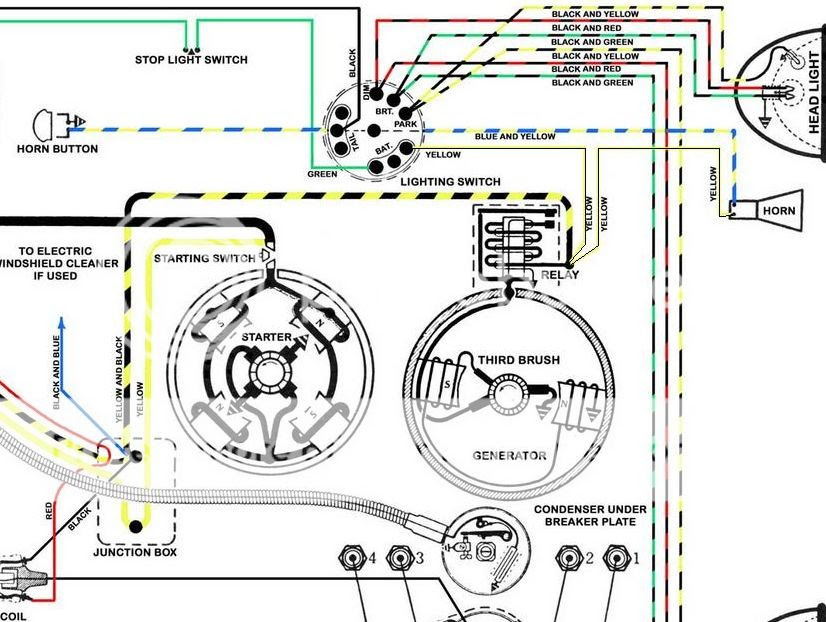
A Model A Ford Wiring Diagram is a detailed schematic that visually represents the electrical system of a Model A Ford automobile. It illustrates the flow of electricity from the battery to the various components, including the starter, ignition system, lighting, gauges, and accessories.
This diagram is crucial for troubleshooting electrical problems, as it allows technicians to trace the circuit paths and identify potential breaks or faults. It also provides guidance for installing new electrical components or modifying the electrical system.
The Model A Ford was a popular car in the 1920s and 1930s, and its electrical system was considered advanced for its time. The wiring diagram has remained relevant over the years, as many Model A Fords are still in use today and require electrical maintenance or restoration.
The Model A Ford Wiring Diagram, a detailed schematic of the electrical system, plays an integral role in the operation and maintenance of Model A Ford automobiles. Understanding its key aspects is crucial for troubleshooting, restoration, and modification of these vehicles.
- Circuitry: The wiring diagram illustrates the complete electrical circuitry, showing the flow of electricity from the battery to the various components.
- Components: It identifies each electrical component in the system, including the starter, ignition coil, lighting, gauges, and accessories.
- Connections: The diagram shows how the components are interconnected, allowing technicians to trace the path of electricity and identify potential breaks or faults.
- Grounding: The wiring diagram indicates the grounding points in the system, which are essential for completing the electrical circuits.
- Wire colors: It specifies the color coding of the wires used in the system, which helps in identifying and tracing circuits.
- Fuse locations: The diagram shows the location of fuses in the system, which protect the electrical components from overcurrent.
- Switch operation: It illustrates how switches control the flow of electricity in the system, allowing various components to be turned on or off.
- Accessory installation: The wiring diagram provides guidance for installing new electrical accessories or modifying the electrical system.
- Troubleshooting: The diagram is invaluable for troubleshooting electrical problems, as it allows technicians to visually trace the circuit paths and identify potential issues.
- Historical significance: The Model A Ford Wiring Diagram reflects the state of electrical engineering in the early 20th century and has remained relevant for maintaining and restoring these classic vehicles.
These key aspects of the Model A Ford Wiring Diagram provide a comprehensive understanding of the electrical system, enabling enthusiasts and professionals to maintain, troubleshoot, and modify these vehicles effectively.
Circuitry
The circuitry forms the backbone of the Model A Ford Wiring Diagram, providing a visual representation of the electrical system’s architecture. It shows how electricity flows from the battery to each component, creating a complete circuit that enables the vehicle’s electrical functions.
Without a clear understanding of the circuitry, troubleshooting electrical problems becomes challenging. The wiring diagram allows technicians to trace the flow of electricity and identify potential breaks or faults in the system. This is crucial for maintaining the vehicle’s electrical integrity and ensuring the proper functioning of its components.
A real-life example of the circuitry’s importance is in diagnosing a faulty headlight. By following the wiring diagram, a technician can trace the circuit from the headlight switch, through the fuse box, and to the headlight itself. This helps them pinpoint the exact location of the problem, whether it’s a blown fuse, a loose connection, or a faulty component.
Understanding the circuitry empowers enthusiasts and professionals to modify the electrical system for specific needs. For instance, installing additional lighting or gauges requires knowledge of the existing circuitry to ensure proper integration without overloading the system.
In summary, the circuitry illustrated in the Model A Ford Wiring Diagram is a critical component for comprehending the electrical system, troubleshooting issues, and making informed modifications. It provides a roadmap for the flow of electricity, enabling enthusiasts and professionals to maintain and enhance the electrical performance of their Model A Fords.
Components
The “Components” section of the Model A Ford Wiring Diagram plays a critical role in understanding the electrical system’s functionality. It provides a comprehensive list of every electrical component, including the starter, ignition coil, lighting, gauges, and accessories. This information is vital for various reasons.
Firstly, it allows technicians to identify and locate specific components within the system. Whether troubleshooting a problem or installing a new accessory, knowing the exact location of each component saves time and effort. For instance, if a headlight is malfunctioning, the wiring diagram will indicate its precise location, enabling the technician to inspect the bulb, wiring, or switch.
Secondly, the “Components” section helps in understanding the interconnections between different components. By tracing the wiring diagram, technicians can see how each component is connected to the power source, ground, and other components. This knowledge is essential for diagnosing electrical problems and ensuring the proper functioning of the system.
Thirdly, the identification of components is crucial for modification and customization. If an enthusiast wants to add additional lighting or install a new gauge, they need to know which components are involved and how they can be integrated into the existing system. The wiring diagram provides this information, allowing for informed decisions and safe modifications.
In summary, the “Components” section of the Model A Ford Wiring Diagram is a critical component for understanding the electrical system, troubleshooting issues, and making informed modifications. It provides a clear picture of the system’s architecture and enables enthusiasts and professionals to maintain and enhance the electrical performance of their Model A Fords.
Connections
The “Connections” section of the Model A Ford Wiring Diagram is a critical component for understanding and maintaining the electrical system of Model A Ford automobiles. It provides a visual representation of how the various electrical components are interconnected, allowing technicians to trace the path of electricity and identify potential breaks or faults.
Understanding the connections is essential for troubleshooting electrical problems. When a component malfunctions, technicians can use the wiring diagram to trace the circuit and identify the point of failure. This systematic approach saves time and effort compared to randomly checking components.
For instance, if a headlight is not working, a technician can use the wiring diagram to trace the circuit from the headlight switch, through the fuse box, and to the headlight itself. By checking the connections at each point, the technician can identify if there is a loose wire, a blown fuse, or a faulty component.
The “Connections” section is also important for modifying the electrical system. If an enthusiast wants to add additional lighting or gauges, they need to understand how these components will be connected to the existing system. The wiring diagram provides this information, ensuring that the modifications are done safely and correctly.
In summary, the “Connections” section of the Model A Ford Wiring Diagram is a critical component for understanding the electrical system, troubleshooting problems, and making informed modifications. It provides a clear picture of the system’s architecture and enables enthusiasts and professionals to maintain and enhance the electrical performance of their Model A Fords.
Grounding
The grounding points in the Model A Ford electrical system, as indicated in the wiring diagram, play a critical role in completing electrical circuits and ensuring the proper functioning of the vehicle’s electrical components. Grounding provides a common reference point for electrical current to flow back to the battery, completing the circuit and allowing electricity to power the various components.
Without proper grounding, electrical circuits cannot be completed, and the electrical system will not function correctly. This can lead to various problems, such as dim lighting, intermittent electrical failures, or even complete electrical failure.
The wiring diagram shows the location of the grounding points in the system, which are typically connected to the vehicle’s chassis or frame. These points provide a low-resistance path for electrical current to flow back to the battery, ensuring that the circuits are completed and the electrical system functions properly.
Understanding the importance of grounding and the location of grounding points in the Model A Ford electrical system is essential for troubleshooting electrical problems and ensuring the proper functioning of the vehicle’s electrical components.
Wire colors
The color coding of wires in the Model A Ford Wiring Diagram plays a critical role in simplifying the identification and tracing of electrical circuits, facilitating troubleshooting and maintenance tasks. Each wire is assigned a specific color based on its function, providing visual cues that help navigate the complex electrical system.
- Circuit Identification: The color coding allows for quick identification of different circuits in the wiring diagram. Wires of the same color are typically part of the same circuit, making it easier to trace the flow of electricity and locate specific components.
- Simplified Troubleshooting: When troubleshooting electrical problems, the color coding helps pinpoint the affected circuit. By following the colored wires, technicians can isolate the issue to a specific area of the system, narrowing down potential causes and reducing diagnostic time.
- Consistent Standards: The standardized color coding ensures consistency across different Model A Ford vehicles, allowing mechanics and enthusiasts to easily understand and work on the electrical system regardless of the specific model or year.
- Historical Significance: The color coding system used in the Model A Ford Wiring Diagram reflects the evolving practices in automotive electrical engineering during the early 20th century, providing insights into the development of standardized electrical systems in vehicles.
In summary, the wire color coding in the Model A Ford Wiring Diagram is a valuable tool for identifying circuits, troubleshooting electrical issues, maintaining consistency, and understanding the historical evolution of automotive electrical systems.
Fuse locations
Within the Model A Ford Wiring Diagram, the fuse locations play a critical role in safeguarding the electrical components from potential damage caused by overcurrent. Fuses act as sacrificial devices, interrupting the flow of electricity when the current exceeds a predetermined threshold, thereby preventing damage to sensitive components.
The wiring diagram clearly indicates the location of each fuse in the system, allowing technicians and enthusiasts to easily identify and replace blown fuses. This is crucial for restoring the functionality of affected electrical components and preventing further damage.
A real-life example of the importance of fuse locations is in troubleshooting a non-functional headlight. By referring to the wiring diagram, a technician can quickly locate the fuse responsible for the headlight circuit. If the fuse is blown, replacing it restores power to the circuit, potentially resolving the issue.
Understanding fuse locations is also essential for modifying or adding new electrical components to the Model A Ford. The wiring diagram provides guidance on the appropriate fuse rating and location for the new circuit, ensuring the system is adequately protected against overcurrent.
In summary, the fuse locations in the Model A Ford Wiring Diagram are a critical component for maintaining the integrity of the electrical system. By protecting components from overcurrent, fuses prevent costly damage and ensure the reliable operation of the vehicle’s electrical systems.
Switch operation
Within the intricate electrical system of the Model A Ford, switches play a pivotal role in regulating the flow of electricity, allowing drivers to control various components and functions of the vehicle. The Model A Ford Wiring Diagram provides a clear illustration of how switches operate, empowering enthusiasts and professionals alike to troubleshoot, modify, and maintain the electrical system effectively.
- Control of Circuits: Switches act as gatekeepers of electricity, interrupting or completing circuits based on their position. By opening or closing the circuit, switches allow specific components to be turned on or off, such as headlights, ignition, and accessories.
- Types of Switches: The Model A Ford utilizes various types of switches, each designed for a specific purpose. Toggle switches, push-button switches, and rotary switches are commonly employed, providing different methods of circuit control.
- Real-Life Example: The ignition switch is a prime example of switch operation in the Model A Ford. When the key is turned, the ignition switch completes the circuit, allowing electricity to flow to the ignition coil and spark plugs, initiating the engine’s combustion process.
- Troubleshooting: Understanding switch operation is crucial for troubleshooting electrical issues. By tracing the wiring diagram and testing switch functionality, technicians can pinpoint faulty switches and restore proper circuit operation.
In summary, the illustration of switch operation in the Model A Ford Wiring Diagram is essential for comprehending the electrical system’s functionality, enabling enthusiasts and professionals to effectively control, troubleshoot, and maintain the electrical components of these classic automobiles.
Accessory installation
Within the context of the Model A Ford Wiring Diagram, the aspect of accessory installation holds significant importance for enthusiasts seeking to customize or enhance their vehicles’ electrical systems. The wiring diagram serves as a valuable guide for adding new electrical accessories or modifying existing ones, ensuring safe and reliable operation.
- Identifying Compatible Accessories: The wiring diagram provides insights into the vehicle’s electrical system, enabling users to assess the compatibility of potential accessories. By understanding the available voltage, amperage, and connection requirements, enthusiasts can select accessories that are suitable for their Model A Ford.
- Planning and Preparation: Before embarking on any accessory installation, the wiring diagram allows for thorough planning and preparation. It helps identify the necessary tools, materials, and wire routing paths, minimizing potential issues during the installation process.
- Real-Life Example: Installing Auxiliary Lighting: Enthusiasts often enhance their Model A Fords with additional lighting, such as fog lights or driving lights. The wiring diagram provides guidance on connecting these accessories to the vehicle’s electrical system, ensuring proper functionality and avoiding overloading.
- Implications for Electrical Modifications: Beyond accessory installation, the wiring diagram is crucial for understanding the implications of electrical modifications. It allows users to trace circuits, assess power consumption, and identify potential conflicts, ensuring that modifications are done safely and without compromising the vehicle’s electrical integrity.
In conclusion, the wiring diagram’s guidance on accessory installation empowers enthusiasts and professionals to customize and modify the electrical systems of their Model A Fords with confidence. By understanding the vehicle’s electrical architecture and the implications of modifications, they can enhance the functionality, safety, and overall driving experience of these classic automobiles.
Troubleshooting
Within the context of the Model A Ford Wiring Diagram, troubleshooting plays a central role in maintaining the electrical integrity and functionality of these classic vehicles. The diagram serves as an invaluable tool for technicians and enthusiasts alike, providing a clear visual representation of the electrical system that simplifies the process of identifying and resolving electrical issues.
The ability to visually trace circuit paths is crucial for effective troubleshooting. By referring to the wiring diagram, technicians can systematically follow the flow of electricity through the system, identifying points of interruption or malfunction. This allows for a targeted approach to troubleshooting, reducing the time and effort required to locate the root cause of electrical problems.
A real-life example of the practical application of troubleshooting through the Model A Ford Wiring Diagram is diagnosing a faulty headlight. By tracing the circuit path from the headlight switch, through the fuse box, and to the headlight itself, a technician can pinpoint the exact location of the problem, whether it’s a blown fuse, a loose connection, or a faulty bulb.
The practical significance of troubleshooting using the Model A Ford Wiring Diagram extends beyond resolving specific electrical issues. It also empowers enthusiasts and professionals to modify and enhance the electrical system safely and confidently. By understanding the circuit paths and potential pitfalls, they can make informed decisions about adding accessories or making modifications, ensuring the overall reliability and performance of the vehicle’s electrical system.
In summary, the troubleshooting aspect of the Model A Ford Wiring Diagram is a critical component for maintaining, repairing, and modifying the electrical systems of these automobiles. It provides a systematic and visual approach to identifying and resolving electrical problems, empowering enthusiasts and professionals alike to keep their Model A Fords running smoothly and safely.
Historical significance
Within the context of “Model A Ford Wiring Diagram,” the historical significance of the diagram cannot be overstated. It provides a glimpse into the state of electrical engineering in the early 20th century and highlights the remarkable evolution of automotive electrical systems. Moreover, it remains a crucial tool for maintaining and restoring these classic vehicles, ensuring their continued operation and preservation.
- Reflection of Early 20th Century Electrical Engineering: The Model A Ford Wiring Diagram showcases the electrical engineering practices and technologies prevalent in the early 1900s. It employs color-coded wires, standardized symbols, and a logical layout, reflecting the emerging industry standards and best practices of the time.
- Evolution of Automotive Electrical Systems: By comparing the Model A Ford Wiring Diagram to those of more modern vehicles, one can trace the significant advancements in automotive electrical systems over the decades. It demonstrates the transition from simple single-wire circuits to complex multi-wire systems, incorporating various electrical components and safety features.
- Maintenance and Restoration: The historical significance of the Model A Ford Wiring Diagram lies not only in its historical value but also in its ongoing relevance for maintaining and restoring Model A Fords. It provides invaluable guidance to enthusiasts and professionals alike, enabling them to troubleshoot electrical issues, make repairs, and restore the vehicle’s electrical system to its original condition.
In conclusion, the historical significance of the Model A Ford Wiring Diagram is multifaceted. It serves as a valuable resource for understanding the evolution of automotive electrical systems, provides insights into early 20th-century electrical engineering practices, and remains an essential tool for the preservation and restoration of these iconic vehicles.


Related Posts


