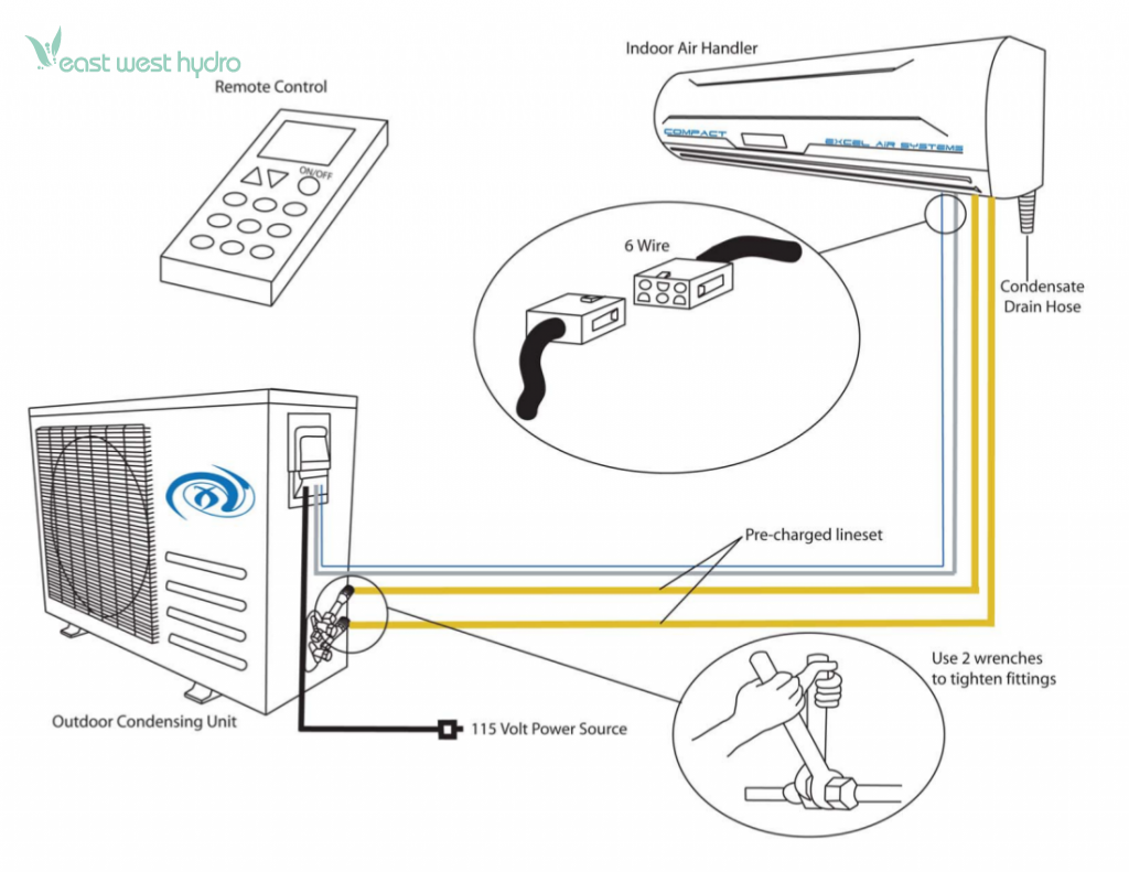
A mini split wiring diagram outlines the electrical connections between the indoor and outdoor units of a mini-split air conditioning system. For instance, in a common 2-zone system, the diagram will depict the wiring for the power supply, refrigerant lines, condensate drain, and communication cables.
Understanding the wiring diagram is crucial for proper installation and maintenance. It ensures the system operates efficiently, providing optimal cooling and heating. One key historical development is the introduction of standardized color coding for wiring, simplifying identification and reducing installation errors.
This article will delve into the components, functions, and essential considerations of a mini-split wiring diagram, providing a comprehensive guide for installers, technicians, and homeowners seeking to optimize their mini-split systems.
Understanding the essential aspects of a mini split wiring diagram is paramount for proper installation, maintenance, and efficient system operation. These key aspects encompass:
- Power supply wiring
- Refrigerant line connections
- Condensate drain routing
- Communication cables
- Circuit breaker/fuse sizing
- Electrical codes and standards
- Safety considerations
- Troubleshooting techniques
- Warranty implications
These aspects are interconnected and impact the overall performance and longevity of the mini-split system. Proper wiring ensures optimal cooling and heating, prevents electrical hazards, and facilitates efficient maintenance. Understanding these aspects enables installers and homeowners to make informed decisions, ensuring the system operates at its peak efficiency and provides years of reliable comfort.
Power supply wiring
Power supply wiring is a critical aspect of a mini split wiring diagram, ensuring the system receives the electrical power necessary for efficient operation. Proper wiring involves connecting the indoor and outdoor units to a dedicated power supply, following electrical codes and standards for safety and reliability.
-
Dedicated circuit
A dedicated circuit is required for each mini-split system to prevent overloading and potential electrical hazards. The circuit should be sized appropriately for the system’s power consumption. -
Circuit breaker/fuse
A circuit breaker or fuse is installed on the dedicated circuit to protect the system from electrical overloads or short circuits. The amperage rating of the circuit breaker/fuse should match the system’s power requirements. -
Wiring gauge
The wiring gauge, or thickness, should be sufficient to handle the current draw of the system. Using undersized wiring can lead to voltage drop and reduced system performance. -
Polarity
Correct polarity is crucial to ensure the system operates properly. The live and neutral wires must be connected to the corresponding terminals on the indoor and outdoor units.
Understanding power supply wiring is essential for installers and homeowners to ensure the safe and efficient operation of their mini-split systems. Proper wiring practices prevent electrical hazards, optimize system performance, and extend the lifespan of the equipment.
Refrigerant line connections
Refrigerant line connections are a critical component of a mini split wiring diagram, as they enable the transfer of refrigerant between the indoor and outdoor units. Proper installation and understanding of these connections are essential for efficient system operation, cooling and heating performance, and overall reliability.
The refrigerant lines consist of two copper pipes, one for high-pressure liquid refrigerant and one for low-pressure gas refrigerant. These lines must be connected correctly to the corresponding ports on the indoor and outdoor units, ensuring a leak-free and efficient flow of refrigerant. Incorrect connections can lead to system malfunctions, reduced cooling/heating capacity, and potential refrigerant leaks.
In a mini split wiring diagram, the refrigerant lines are typically represented by color-coded wires, making it easier for installers to identify and connect them correctly. The diagram also specifies the size and type of refrigerant lines required, as well as the proper routing and support methods to prevent damage or leaks. Understanding the refrigerant line connections in the wiring diagram is crucial for ensuring proper system operation, preventing costly repairs, and maintaining optimal energy efficiency.
Overall, the connection between refrigerant line connections and mini split wiring diagrams is vital for the safe, efficient, and reliable operation of the system. Proper installation and understanding of these connections empower homeowners and installers to ensure optimal performance, extended system lifespan, and reduced energy consumption.
Condensate drain routing
In the context of a mini split wiring diagram, condensate drain routing plays a crucial role in ensuring the efficient and reliable operation of the system. Condensate, a byproduct of the cooling process, must be properly drained away to prevent leaks, mold growth, and system malfunctions. Understanding and adhering to proper condensate drain routing guidelines outlined in the wiring diagram are essential.
-
Drain hose
The drain hose is a flexible tube that carries condensate from the indoor unit to an appropriate drain location, such as a sink, floor drain, or condensate pump. -
Drain pan
The drain pan is a shallow pan located beneath the indoor unit that collects condensate before it is drained away through the drain hose. -
Trap
A trap is a U-shaped section of the drain line that prevents sewer gases from entering the indoor space through the drain hose. -
Slope
The drain line must be sloped downward to ensure proper drainage and prevent condensate from accumulating in the line.
Proper condensate drain routing, as specified in the mini split wiring diagram, not only ensures the efficient removal of condensate but also prevents potential issues such as water damage, unpleasant odors, and system breakdowns. By adhering to the guidelines outlined in the wiring diagram, installers and homeowners can ensure the longevity, reliability, and optimal performance of their mini split systems.
Communication cables
Communication cables play a critical role in mini split wiring diagrams, enabling communication and data exchange between the indoor and outdoor units of the mini split system. Proper understanding and installation of these cables are crucial for efficient system operation, monitoring, and control.
-
Signal transmission
Communication cables transmit control signals, sensor data, and error codes between the indoor and outdoor units. This enables the system to adjust its operation based on room conditions, ensuring optimal comfort and energy efficiency.
-
Remote control
Communication cables allow for remote control of the mini split system using a wired or wireless remote controller. This provides convenient and user-friendly operation, enabling adjustments to temperature, fan speed, and other settings from anywhere within the covered area.
-
Diagnostics and troubleshooting
Communication cables facilitate diagnostic and troubleshooting functions. Error codes and system parameters can be transmitted to a central controller or monitoring system, allowing technicians to quickly identify and resolve any issues, minimizing downtime and ensuring system reliability.
-
Integration with smart home systems
In modern homes, communication cables enable the integration of mini split systems with smart home systems. This allows for remote monitoring, scheduling, and control of the system through smartphones, tablets, or voice assistants, enhancing convenience and energy management.
Overall, communication cables are an integral part of mini split wiring diagrams, providing the means for data exchange, remote control, diagnostics, and integration with smart home systems. Understanding and adhering to the wiring diagram guidelines ensure optimal system performance, user convenience, and efficient energy management.
Circuit breaker/fuse sizing
Circuit breaker/fuse sizing is a critical aspect of mini split wiring diagrams, ensuring the electrical safety and optimal performance of the system. Proper sizing prevents electrical hazards, safeguards components, and ensures efficient system operation.
-
Amperage rating
The amperage rating of the circuit breaker/fuse must match the maximum current draw of the mini split system. Undersized circuit breakers/fuses can trip prematurely, disrupting system operation, while oversized ones may fail to protect against electrical overloads.
-
Wire gauge
The wire gauge used for the circuit breaker/fuse must be appropriate for the amperage rating. Undersized wires can overheat and pose a fire hazard, while oversized wires may not provide adequate protection.
-
Type
The type of circuit breaker/fuse used must be compatible with the electrical system and the mini split system. Common types include standard circuit breakers, thermal magnetic circuit breakers, and fuses.
-
Location
Circuit breakers/fuses should be easily accessible for maintenance and troubleshooting. They are typically installed in the main electrical panel or a dedicated sub-panel for the mini split system.
Proper circuit breaker/fuse sizing ensures that the mini split system operates within safe electrical limits. It prevents damage to components, reduces the risk of electrical fires, and maintains optimal system performance. Understanding and adhering to the circuit breaker/fuse sizing specifications in the mini split wiring diagram is crucial for the safe and efficient operation of the system.
Electrical codes and standards
Electrical codes and standards play a crucial role in mini split wiring diagrams, ensuring the safe and compliant installation and operation of mini split systems. These codes and standards establish minimum requirements for electrical components, wiring methods, and safety measures to prevent electrical hazards, fires, and injuries. Adhering to these codes and standards is critical for the reliable and efficient operation of mini split systems.
One of the key aspects of electrical codes and standards in mini split wiring diagrams is the specification of wire sizes and types. The correct wire size ensures that the wires can safely carry the electrical current required by the mini split system without overheating or causing voltage drop. Electrical codes also specify the types of wires that can be used for different applications, such as stranded wires for flexible connections and solid wires for fixed wiring.
Another important aspect of electrical codes and standards is the requirement for proper grounding. Grounding provides a safe path for electrical current to flow in case of a fault, preventing electrical shocks and damage to equipment. Mini split wiring diagrams must include grounding conductors and specify the proper connection points to ensure effective grounding.
By understanding and following electrical codes and standards, installers and homeowners can ensure that their mini split systems are installed and operated safely and efficiently. These codes and standards provide a framework for proper electrical practices, minimizing the risk of electrical hazards and ensuring the longevity and reliability of mini split systems.
Safety considerations
Safety considerations are paramount in the context of mini split wiring diagrams, as they provide essential guidelines for the safe installation, operation, and maintenance of mini split systems. These considerations encompass various aspects of electrical safety, fire prevention, and personal protection, ensuring the well-being of users and preventing potential hazards.
One critical component of safety considerations in mini split wiring diagrams is proper grounding. Grounding provides a safe path for electrical current to flow in the event of a fault, preventing electrical shocks and damage to equipment. The wiring diagram specifies the grounding conductors and the appropriate connection points to ensure effective grounding, minimizing the risk of electrical accidents.
Another important safety consideration is the use of appropriate wire sizes and types. The wiring diagram specifies the minimum wire size required for each circuit, ensuring that the wires can safely carry the electrical current without overheating or causing voltage drop. The diagram also indicates the types of wires suitable for different applications, such as stranded wires for flexible connections and solid wires for fixed wiring, ensuring proper electrical connections and preventing potential fire hazards.
Furthermore, safety considerations in mini split wiring diagrams include guidelines for proper installation techniques, such as securing electrical connections, routing wires safely to avoid damage or entanglement, and maintaining proper clearances from flammable materials. By adhering to these guidelines, installers can minimize the risk of electrical fires and ensure the safe operation of the mini split system.
Troubleshooting techniques
Troubleshooting techniques are an essential aspect of mini split wiring diagrams, providing valuable insights for diagnosing and resolving system malfunctions. They equip homeowners and technicians with a structured approach to identify and rectify issues, ensuring optimal system performance and comfort.
-
Error codes
Mini split systems often display error codes on their control panels or diagnostic tools. Troubleshooting techniques involve interpreting these codes and referencing the wiring diagram to identify the corresponding fault or malfunction. This enables targeted troubleshooting and efficient resolution.
-
Voltage measurements
Using a multimeter, technicians can measure voltage at various points in the wiring diagram to verify power supply, circuit integrity, and component functionality. By comparing measured values to specified ranges, faults can be isolated and the root cause can be determined.
-
Component inspection
Physical inspection of components, such as capacitors, contactors, and circuit boards, can reveal signs of damage or wear. Troubleshooting techniques guide technicians to identify common failure points and perform continuity tests to assess component functionality.
-
Refrigerant leak detection
Refrigerant leaks can impair system performance and pose safety hazards. Troubleshooting techniques involve using specialized leak detectors to identify leaks along the refrigerant lines and connections. Prompt leak detection and repair ensure optimal system operation and prevent refrigerant loss.
Understanding and applying these troubleshooting techniques empower homeowners and technicians to diagnose and resolve mini split system issues effectively. By navigating the wiring diagram and utilizing appropriate tools, they can minimize downtime, maintain system efficiency, and ensure a comfortable indoor environment.
Warranty implications
Understanding the warranty implications associated with a mini split wiring diagram is crucial for both homeowners and contractors. The wiring diagram not only guides the installation and maintenance of the system but also serves as a reference point for determining warranty coverage and potential exclusions.
-
Proper Installation
The wiring diagram provides detailed instructions for installing the mini split system according to the manufacturer’s specifications. If the system is not installed correctly, it may void the warranty, leaving the homeowner responsible for repair costs.
-
Unauthorized Modifications
Any modifications made to the wiring diagram or the system itself without the manufacturer’s approval can void the warranty. This includes changes to the refrigerant lines, electrical connections, or control settings.
-
Genuine Parts
Using genuine parts recommended by the manufacturer is essential for maintaining warranty coverage. Substituting generic or aftermarket parts may compromise the system’s performance and safety, potentially voiding the warranty.
-
Regular Maintenance
Regular maintenance, as outlined in the wiring diagram, is crucial for preserving warranty coverage. Neglecting maintenance tasks, such as cleaning the filters or checking refrigerant levels, can lead to system malfunctions and void the warranty.
Adhering to the guidelines and specifications provided in the mini split wiring diagram is paramount for maintaining warranty coverage. By following the manufacturer’s instructions, using genuine parts, and performing regular maintenance, homeowners can protect their investment and ensure the long-term performance and reliability of their mini split system.


Related Posts


