A Mercury Outboard Ignition Switch Wiring Diagram is a schematic representation of the electrical connections within the ignition system of a Mercury outboard motor. It guides the user in understanding the arrangement and functionality of the ignition switch, which is crucial for starting and operating the engine.
The ignition switch plays a central role in the outboard motor’s ignition system. It serves as the primary means of controlling the flow of electrical current to various components, including the ignition coil, starter solenoid, and fuel pump. By following the wiring diagram, technicians and boat owners can troubleshoot ignition problems, perform maintenance, and ensure proper operation of the outboard motor.
Over the years, Mercury has made significant advancements in its ignition switch technology. In the early days, outboard motors used simple mechanical ignition switches. However, with the advent of electronic ignition systems, Mercury introduced advanced ignition switches that incorporate multiple safety features and provide enhanced reliability and performance. These advancements have contributed to the overall safety and efficiency of Mercury outboard motors.
A Mercury Outboard Ignition Switch Wiring Diagram provides a comprehensive understanding of the electrical connections within an outboard motor’s ignition system. It is crucial for troubleshooting, maintenance, and ensuring optimal performance. The diagram outlines the key aspects of the ignition switch, detailing its components, functionality, and interconnections.
- Components: The wiring diagram identifies the various components of the ignition switch, such as terminals, contacts, and relays.
- Functionality: It explains the role of the ignition switch in controlling the flow of electrical current to different components of the ignition system.
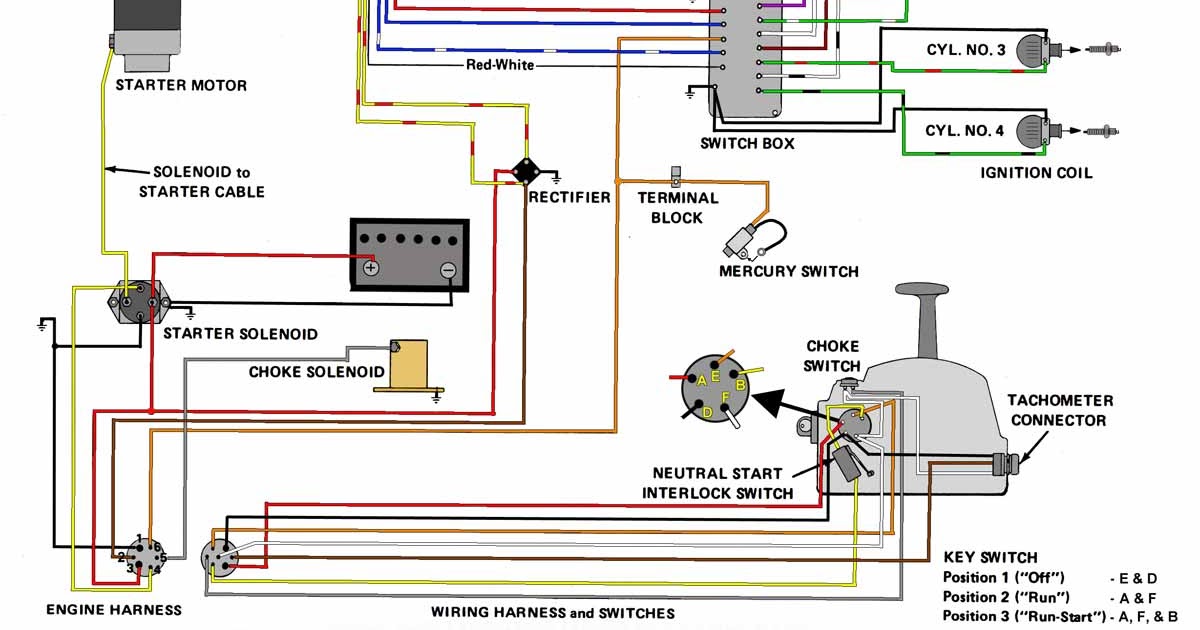
- Circuitry: The diagram illustrates the electrical pathways and connections between the ignition switch, battery, ignition coil, starter solenoid, and other related components.
- Safety Features: Advanced ignition switches incorporate safety features such as lanyard kill switches and overheat protection, which are highlighted in the diagram.
- Troubleshooting: The wiring diagram serves as a guide for technicians to diagnose and resolve ignition-related issues.
- Maintenance: It provides information on how to properly maintain and service the ignition switch to ensure its longevity and reliability.
- Compatibility: The diagram specifies the compatibility of the ignition switch with different Mercury outboard motor models and years.
- Installation: It includes instructions on how to correctly install and wire the ignition switch, ensuring proper functionality.
These key aspects provide a comprehensive understanding of the Mercury Outboard Ignition Switch Wiring Diagram, empowering users to maintain, troubleshoot, and optimize the performance of their outboard motors.
Components
Within the Mercury Outboard Ignition Switch Wiring Diagram, the identification of various components is crucial for understanding the ignition system’s functionality and performing maintenance and troubleshooting tasks. The wiring diagram outlines these components, their interconnections, and their roles in the overall ignition process.
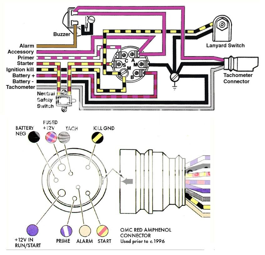
- Terminals: The ignition switch has multiple terminals that serve as connection points for electrical wires. These terminals are labeled to indicate their specific functions, such as battery power, starter solenoid, and ignition coil. Proper identification of terminals ensures correct wiring and prevents electrical faults.
- Contacts: Contacts are electrical switches within the ignition switch that open and close circuits to control the flow of current. The wiring diagram shows the configuration and operation of these contacts, enabling technicians to diagnose and repair ignition switch malfunctions.
- Relays: Relays are electromagnetic switches that are controlled by the ignition switch. They amplify the current supplied by the ignition switch to operate high-power components, such as the starter motor. The wiring diagram indicates the location and function of relays, aiding in fault-finding and replacement.
- Safety Features: Advanced ignition switches incorporate safety features such as lanyard kill switches and overheat protection. The wiring diagram illustrates how these features are integrated into the ignition switch circuit, ensuring the safe operation of the outboard motor.
By understanding the components of the ignition switch and their interconnections as outlined in the Mercury Outboard Ignition Switch Wiring Diagram, users can effectively maintain, troubleshoot, and optimize the performance of their outboard motors.
Functionality
Within the broader context of the Mercury Outboard Ignition Switch Wiring Diagram, understanding the functionality of the ignition switch is crucial. The ignition switch serves as the central control point for regulating the flow of electrical current to various components within the ignition system, initiating and maintaining the engine’s operation. Several key aspects highlight its functionality:
- Starter Solenoid: When the ignition switch is turned to the “start” position, it supplies power to the starter solenoid, engaging the starter motor and cranking the engine.
- Ignition Coil: The ignition switch provides continuous power to the ignition coil, which generates the high-voltage spark required for ignition.
- Fuel Pump: In some models, the ignition switch also powers the fuel pump, ensuring a steady supply of fuel to the engine.
- Safety Features: Advanced ignition switches incorporate safety features such as lanyard kill switches. When the lanyard is pulled, the ignition switch cuts off power to the engine, preventing unintended operation.
Overall, the functionality of the ignition switch is intricately linked to the proper operation of the outboard motor’s ignition system. By controlling the flow of electrical current to essential components, the ignition switch plays a pivotal role in starting, running, and stopping the engine, ensuring a reliable and efficient boating experience.
Circuitry
Within the context of a Mercury Outboard Ignition Switch Wiring Diagram, the circuitry plays a vital role in orchestrating the flow of electrical current throughout the ignition system. The diagram meticulously outlines the intricate network of electrical pathways and connections, establishing the cause-and-effect relationships between the ignition switch and other critical components.
When the ignition switch is turned to the “start” position, it triggers a cascade of events initiated by the circuitry. Electrical current flows from the battery to the ignition switch, which then directs it to the starter solenoid. This initiates the engagement of the starter motor, cranking the engine and commencing the combustion process. Simultaneously, the ignition switch supplies continuous power to the ignition coil, prompting the generation of high-voltage sparks that ignite the air-fuel mixture within the engine’s cylinders. In some models, the ignition switch also powers the fuel pump, ensuring a steady supply of fuel for smooth engine operation.
The circuitry within the Mercury Outboard Ignition Switch Wiring Diagram serves as the nervous system of the ignition system, allowing the ignition switch to control and coordinate the actions of various components. Understanding this circuitry empowers technicians and boat owners to diagnose electrical faults, perform maintenance tasks, and optimize the performance of their outboard motors. By tracing the electrical pathways and connections outlined in the diagram, they can pinpoint issues and implement effective solutions, ensuring reliable and efficient operation on the water.
Safety Features
Within the Mercury Outboard Ignition Switch Wiring Diagram, safety features play a crucial role in ensuring the safe operation of the outboard motor. Advanced ignition switches incorporate essential safety features such as lanyard kill switches and overheat protection, highlighted prominently in the diagram to emphasize their significance.
The lanyard kill switch is a critical safety component connected to the ignition switch. When the operator moves away from the helm or if the lanyard is accidentally pulled, it triggers the ignition switch to cut off power to the engine, preventing unintended acceleration and potential accidents. The wiring diagram illustrates the electrical connections and circuitry associated with the lanyard kill switch, enabling technicians to verify its proper installation and functionality.
Overheat protection is another vital safety feature highlighted in the Mercury Outboard Ignition Switch Wiring Diagram. The ignition switch monitors the engine’s temperature and, if excessive heat is detected, it initiates a shutdown procedure to protect the engine from damage. The wiring diagram provides insights into how the ignition switch interacts with temperature sensors and relays to implement this safety mechanism.
Understanding the safety features incorporated into the Mercury Outboard Ignition Switch Wiring Diagram is essential for ensuring the safe operation of the outboard motor. By studying the diagram, boat owners and technicians can gain a thorough understanding of how these safety features are integrated into the ignition system, allowing them to troubleshoot any issues and ensure the continued safe operation of the outboard motor.
Troubleshooting
Within the realm of Mercury Outboard Ignition Switch Wiring Diagrams, troubleshooting plays a pivotal role in maintaining optimal engine performance and ensuring a safe boating experience. The wiring diagram serves as an invaluable tool for technicians, providing a comprehensive guide to diagnose and resolve ignition-related issues effectively.
- Identifying Electrical Faults: The wiring diagram allows technicians to trace electrical pathways, pinpoint faulty connections, and identify malfunctioning components within the ignition system. By systematically testing voltage and continuity, they can isolate the root cause of ignition problems.
- Understanding Component Interactions: The wiring diagram illustrates the interconnectedness of various ignition components, such as the ignition switch, starter solenoid, and ignition coil. By studying the diagram, technicians can gain a clear understanding of how these components interact and affect the overall ignition process.
- Resolving Intermittent Issues: Ignition problems can sometimes be intermittent, making them difficult to diagnose. The wiring diagram enables technicians to analyze the electrical circuits under different operating conditions, helping them identify intermittent faults and implement lasting solutions.
- Ensuring Accurate Repairs: By following the wiring diagram, technicians can ensure accurate repairs and prevent further electrical issues. The diagram provides precise instructions on wire routing, terminal connections, and component replacements, minimizing the risk of incorrect installations.
In conclusion, the troubleshooting aspect of Mercury Outboard Ignition Switch Wiring Diagrams is crucial for maintaining reliable outboard motor operation. The wiring diagram empowers technicians with the knowledge and guidance to diagnose and resolve ignition-related issues efficiently, ensuring a safe and enjoyable boating experience for all.
Maintenance
Within the context of Mercury Outboard Ignition Switch Wiring Diagrams, maintenance plays a crucial role in preserving the optimal performance and lifespan of the ignition system. The wiring diagram encompasses essential information on how to properly maintain and service the ignition switch, ensuring its longevity and reliability, and extending the overall life of the outboard motor.
- Regular Inspection: The wiring diagram guides users on how to perform regular inspections of the ignition switch, identifying any signs of wear, corrosion, or loose connections. By promptly addressing these issues, potential failures can be prevented, ensuring uninterrupted operation.
- Terminal Cleaning: Over time, terminals on the ignition switch can accumulate dirt and corrosion, affecting electrical conductivity and leading to ignition problems. The wiring diagram provides instructions on how to safely clean and maintain the terminals, optimizing electrical connections.
- Lubrication: In certain ignition switch designs, lubrication is crucial for smooth operation and reduced wear. The wiring diagram specifies the type and frequency of lubrication required, ensuring optimal performance and extending the lifespan of the switch.
- Corrosion Prevention: Exposure to moisture and salt air can lead to corrosion on the ignition switch. The wiring diagram provides guidance on how to protect the switch from corrosion using protective sprays or coatings, ensuring long-term durability in harsh marine environments.
Understanding and following the maintenance guidelines outlined in the Mercury Outboard Ignition Switch Wiring Diagram empowers users to proactively maintain their ignition system, minimizing downtime, maximizing engine performance, and ensuring a safe and enjoyable boating experience.
Compatibility
Within the comprehensive Mercury Outboard Ignition Switch Wiring Diagram, compatibility plays a vital role in ensuring seamless integration and optimal performance of the ignition system. The diagram meticulously outlines the compatibility of the ignition switch across various Mercury outboard motor models and years, providing valuable guidance for users seeking to select the correct replacement part or troubleshoot ignition issues.
- Model-Specific Ignition Switches: Mercury outboard motors employ model-specific ignition switches designed to match the electrical characteristics and configurations of each engine. The wiring diagram specifies the compatibility of the ignition switch with different outboard motor models, enabling users to identify the correct switch for their specific engine.
- Year Range Compatibility: Ignition switch compatibility also extends to specific year ranges within each outboard motor model. The wiring diagram indicates the years for which the ignition switch is compatible, ensuring that users select a switch that matches the electrical system of their outboard motor.
- Electrical Interface Compatibility: The ignition switch must be compatible with the electrical interface of the outboard motor. The wiring diagram provides information on the number and arrangement of terminals on the ignition switch, ensuring that it can be correctly connected to the existing wiring harness.
- Safety Feature Compatibility: Advanced ignition switches incorporate safety features such as lanyard kill switches and overheat protection. The wiring diagram ensures compatibility of these safety features with the specific outboard motor model and year, maintaining a consistent level of protection across different engines.
Understanding the compatibility aspect of the Mercury Outboard Ignition Switch Wiring Diagram empowers users to make informed decisions when selecting and installing a replacement ignition switch. By following the compatibility guidelines outlined in the diagram, users can ensure that the ignition switch seamlessly integrates with their outboard motor, providing reliable and efficient operation for years to come.
Installation
Within the context of the Mercury Outboard Ignition Switch Wiring Diagram, the installation instructions play a critical role in ensuring the successful integration and optimal performance of the ignition system. These instructions provide a step-by-step guide on how to correctly install and wire the ignition switch, ensuring that it seamlessly interfaces with the outboard motor’s electrical system.
The ignition switch serves as the central control point for the ignition system, responsible for managing the flow of electrical current to various components, including the starter solenoid, ignition coil, and fuel pump. Proper installation of the ignition switch is paramount to ensure that these components receive the correct electrical signals at the appropriate times, enabling the engine to start, run, and stop as intended.
The wiring diagram provides detailed instructions on how to connect the ignition switch to the boat’s electrical system. It specifies the wire colors, terminal connections, and routing of the wiring harness, ensuring that all components are correctly interconnected. By following these instructions carefully, users can avoid electrical faults, ensure proper operation of the ignition system, and maintain a high level of safety on the water.
In summary, the installation instructions included in the Mercury Outboard Ignition Switch Wiring Diagram are a critical component for successful ignition system integration. They provide clear and concise guidance on how to correctly install and wire the ignition switch, ensuring reliable engine operation and enhancing the overall boating experience.


Related Posts


