Mercruiser Trim Sender Wiring Diagram: A comprehensive schematic representing the electrical connections between the trim sender unit and other components in a Mercruiser marine engine system. It provides a visual representation of how these components are wired together to enable proper operation of the outboard motor’s trim system.
Importance, Benefits, and Historical Context:
- Assists in troubleshooting and repairing electrical issues related to the trim system.
- Enables efficient installation and maintenance of the trim sender unit.
- Provides a reference for understanding the system’s electrical architecture.
- Key historical development: The introduction of electronic trim systems in the 1980s led to the need for detailed wiring diagrams to support their complex electrical configurations.
Transition:This article delves into the specifics of the Mercruiser Trim Sender Wiring Diagram, its components, and how it supports the proper functioning of the trim system, ensuring optimal performance and safety on the water.
The Mercruiser Trim Sender Wiring Diagram is a vital part of the Mercruiser marine engine system, providing a comprehensive representation of the electrical connections between the trim sender unit and other system components. Understanding its essential aspects is crucial for proper installation, maintenance, and troubleshooting of the trim system.
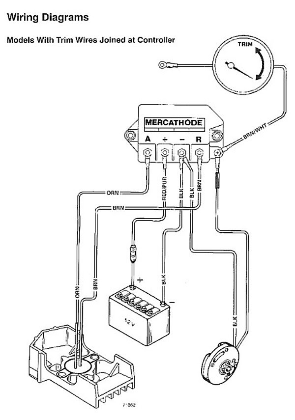
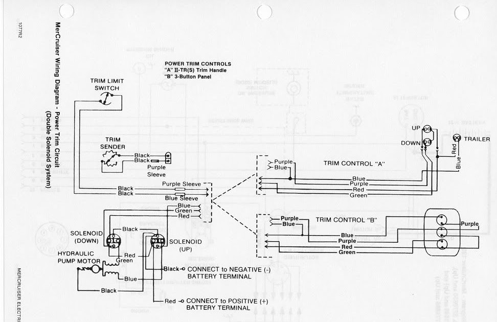
- Components: Trim sender unit, trim gauge, engine control module (ECM), wiring harness
- Function: Transmits trim angle data from the trim sender unit to the trim gauge and ECM
- Wiring: Color-coded wires for easy identification and connection
- Connections: Diagram shows how each component is electrically connected to the others
- Troubleshooting: Guide for diagnosing electrical issues related to the trim system
- Maintenance: Reference for inspecting and servicing the trim sender and wiring
- Safety: Proper wiring is essential for safe operation of the trim system
- Performance: Accurate trim angle data ensures optimal engine performance
- Compatibility: Specific to Mercruiser engines and trim systems
- Technical Support: Available from Mercruiser or authorized dealers
These aspects collectively contribute to the effectiveness and reliability of the Mercruiser Trim Sender Wiring Diagram. By understanding and utilizing it correctly, marine technicians and boat owners can ensure the proper functioning of the trim system, enhancing the overall performance and safety of the boat.
Components
The Mercruiser Trim Sender Wiring Diagram outlines the electrical connections between various components that work together to ensure proper operation of the trim system. These components play crucial roles in data transmission, control, and power distribution.
-
Trim sender unit:
Senses the trim angle of the outboard motor and transmits this data to the trim gauge and ECM. -
Trim gauge:
Provides a visual indication of the trim angle, allowing the operator to adjust it for optimal performance and fuel efficiency. -
Engine control module (ECM):
Receives data from the trim sender unit and other sensors to control fuel injection, ignition timing, and other engine parameters. -
Wiring harness:
Connects all the components of the trim system, providing a pathway for electrical signals and power.
These components are essential for the proper functioning of the Mercruiser trim system. By understanding their roles and connections as defined in the Trim Sender Wiring Diagram, technicians and boat owners can effectively troubleshoot, maintain, and optimize the system for a safe and enjoyable boating experience.
Function
The Mercruiser Trim Sender Wiring Diagram depicts the electrical connections that enable the transmission of trim angle data from the trim sender unit to the trim gauge and Engine Control Module (ECM). This data plays a pivotal role in optimizing engine performance, fuel efficiency, and overall boat handling.
- Trim sender unit: Senses the trim angle of the outboard motor using a potentiometer and transmits this data as an electrical signal.
- Wiring harness: Provides a protected pathway for the electrical signal from the trim sender unit to the trim gauge and ECM.
- Trim gauge: Receives the electrical signal and displays the trim angle on a gauge, allowing the operator to adjust the trim for optimal performance.
- ECM: Receives the trim angle data from the trim sender unit and adjusts engine parameters such as fuel injection and ignition timing to enhance performance and efficiency.
The accurate transmission of trim angle data is crucial for the proper functioning of the Mercruiser trim system. By understanding the components and connections involved in this data transmission, technicians and boat owners can effectively troubleshoot and maintain the system, ensuring a safe and enjoyable boating experience.
Wiring
The Mercruiser Trim Sender Wiring Diagram utilizes color-coded wires for easy identification and connection, ensuring efficient installation, maintenance, and troubleshooting of the trim system. This wiring scheme plays a vital role in the proper functioning of the system.
Color-coded wires simplify the identification of individual wires within the wiring harness. Each wire is assigned a specific color code, which corresponds to its function and connection point. This color-coding eliminates confusion and reduces the risk of incorrect connections, which can lead to electrical malfunctions or damage to the system.
For instance, in the Mercruiser Trim Sender Wiring Diagram, the wire connecting the trim sender unit to the trim gauge may be color-coded blue, while the wire connecting the trim sender unit to the ECM may be color-coded green. This color-coding enables technicians to quickly trace the path of each wire and identify its purpose, facilitating efficient troubleshooting and repairs.
The use of color-coded wires in the Mercruiser Trim Sender Wiring Diagram streamlines the installation process, allowing for quick and accurate connections. It also enhances the reliability of the system by minimizing the likelihood of incorrect wiring, which can cause electrical issues or system failures.
In summary, the color-coding of wires in the Mercruiser Trim Sender Wiring Diagram is a critical component that simplifies identification, ensures accurate connections, and enhances the overall reliability and functionality of the trim system.
Connections
Within the Mercruiser Trim Sender Wiring Diagram, the connections between components play a crucial role in ensuring the proper functioning of the trim system. The diagram provides a visual representation of how each component is electrically connected to the others, enabling technicians and boat owners to understand and troubleshoot the system effectively.
- Component Identification: The diagram clearly labels each component, including the trim sender unit, trim gauge, engine control module (ECM), and wiring harness. This identification simplifies the process of tracing connections and identifying potential issues.
- Color-Coding: Wires in the diagram are color-coded to match the actual wiring harness, making it easier to identify and connect wires during installation and maintenance. This color-coding reduces the risk of incorrect connections, which can lead to electrical problems or system malfunctions.
- Connector Types: The diagram specifies the types of connectors used for each connection, such as bullet connectors, ring terminals, or plug-in connectors. This information guides technicians in selecting the appropriate tools and techniques for making secure and reliable connections.
- Wire Routing: The diagram shows the routing of wires throughout the system, including the location of wire bundles, clamps, and grommets. This information helps technicians avoid potential interference or damage to wires during installation and maintenance.
Understanding the connections between components in the Mercruiser Trim Sender Wiring Diagram is essential for proper system installation, maintenance, and troubleshooting. The diagram provides a valuable reference for technicians and boat owners, ensuring the safe and reliable operation of the trim system, which is critical for optimal boat performance and handling.
Troubleshooting
Within the Mercruiser Trim Sender Wiring Diagram, the troubleshooting aspect serves as a valuable guide for diagnosing electrical issues related to the trim system. It equips technicians and boat owners with a systematic approach to identifying and resolving electrical faults, ensuring optimal system performance and safety on the water.
- Identifying Potential Parts: The diagram helps pinpoint potential faulty components within the trim system. By analyzing the electrical connections and wire routing, technicians can narrow down the search for issues such as loose connections, damaged wires, or malfunctioning sensors.
- Real-Life Examples: Troubleshooting scenarios are often illustrated with real-life examples, enabling technicians to relate to common electrical problems. These examples may include intermittent trim gauge readings, inoperative trim motor, or abnormal trim behavior under load.
- Electrical Measurement Techniques: The diagram provides guidance on using electrical measurement tools such as multimeters and oscilloscopes to diagnose electrical issues. Technicians can follow step-by-step instructions to measure voltage, resistance, and continuity, helping them isolate and identify faulty components.
- Implications of Troubleshooting: Accurate troubleshooting not only resolves electrical issues but also contributes to preventive maintenance. By identifying and addressing potential problems early on, technicians can minimize the risk of more severe damage to the trim system or other boat components.
The troubleshooting aspect of the Mercruiser Trim Sender Wiring Diagram empowers technicians and boat owners with the knowledge and tools to diagnose and resolve electrical issues related to the trim system. This ensures the safe and reliable operation of the trim system, contributing to an enjoyable and worry-free boating experience.
Maintenance
Within the Mercruiser Trim Sender Wiring Diagram, the maintenance aspect serves as a vital reference for inspecting and servicing the trim sender and wiring, ensuring the system’s optimal performance and longevity. It provides detailed guidance on various maintenance procedures, enabling technicians and boat owners to proactively maintain and troubleshoot the trim system, preventing potential issues and ensuring safe and reliable operation.
- Identifying Potential Issues: The diagram helps identify potential issues that may arise with the trim sender and wiring, such as loose connections, corrosion, or wire damage. By understanding the common failure points, technicians can focus their inspection and maintenance efforts accordingly.
- Inspection Procedures: Step-by-step inspection procedures are outlined, guiding technicians through the process of checking electrical connections, wire insulation, and the functionality of the trim sender unit. These procedures ensure thorough and systematic inspection, minimizing the chances of missing potential problems.
- Servicing and Repair: If any issues are identified during the inspection, the diagram provides guidance on servicing and repair procedures. This may include instructions on tightening connections, replacing damaged wires, or troubleshooting and replacing faulty trim sender units.
- Preventive Maintenance: The maintenance reference also emphasizes the importance of preventive maintenance to extend the lifespan of the trim system. Regular inspections and servicing can help prevent minor issues from developing into larger problems, reducing downtime and ensuring the system’s reliability.
The maintenance aspect of the Mercruiser Trim Sender Wiring Diagram is an invaluable resource for maintaining the health and functionality of the trim system. By following the inspection and servicing guidelines provided in the diagram, technicians and boat owners can proactively address potential issues, ensuring the system’s optimal performance and safety on the water.
Safety
Within the Mercruiser Trim Sender Wiring Diagram, the safety aspect is paramount, as proper wiring is indispensable for the safe and reliable operation of the trim system. Incorrect wiring or electrical faults can lead to various hazards, emphasizing the critical nature of adhering to the guidelines outlined in the diagram.
- Electrical Hazards: Faulty wiring can create electrical hazards such as short circuits, which can cause fires or damage to electrical components. Proper wiring ensures that electrical connections are secure and insulated to prevent such hazards.
- Trim System Malfunctions: Improper wiring can lead to malfunctions in the trim system, affecting its ability to adjust the boat’s trim angle. This can compromise the boat’s handling and stability, potentially leading to dangerous situations on the water.
- Water Ingress: Boats are exposed to water, and improper wiring can create entry points for water to penetrate electrical connections. This can lead to corrosion and electrical shorts, posing safety risks and affecting the reliability of the trim system.
- Compliance and Regulations: Many regions have regulations governing the electrical safety of boats. Proper wiring ensures compliance with these regulations, reducing the risk of legal liabilities and contributing to the overall safety of the boat.
Adhering to the safety guidelines provided in the Mercruiser Trim Sender Wiring Diagram is crucial for ensuring the safe and reliable operation of the trim system. By following the recommended wiring practices and maintaining proper electrical connections, boat owners and technicians can minimize electrical hazards, prevent trim system malfunctions, and enhance the overall safety of their boating experience.
Performance
Within the context of the Mercruiser Trim Sender Wiring Diagram, accurate trim angle data is essential for optimal engine performance. The trim angle directly affects the boat’s efficiency, speed, and handling characteristics. By providing precise trim angle information, the trim sender unit ensures that the engine operates at its optimal trim angle, resulting in improved performance and a more enjoyable boating experience.
- Fuel Efficiency: Accurate trim angle data allows the engine to operate at its most fuel-efficient trim angle. This reduces fuel consumption and increases the boat’s range.
- Speed: Proper trim angle reduces drag and improves the boat’s overall speed and acceleration. This is especially important for high-performance boats.
- Handling: Correct trim angle enhances the boat’s handling characteristics, making it more responsive and stable. This is particularly noticeable when the boat is cornering or operating in rough water.
- Reduced Wear and Tear: Operating the engine at the correct trim angle reduces stress on the engine and drivetrain components, leading to extended lifespan and reduced maintenance costs.
The Mercruiser Trim Sender Wiring Diagram provides the electrical connections necessary for the trim sender unit to transmit accurate trim angle data to the engine’s ECM. This ensures that the engine can adjust its operating parameters, such as fuel injection and ignition timing, to optimize performance based on the boat’s current trim angle. By adhering to the wiring diagram’s specifications, boat owners and technicians can ensure that the trim system operates correctly, maximizing engine performance and enhancing the overall boating experience.
Compatibility
The “Compatibility: Specific to Mercruiser engines and trim systems” aspect of the Mercruiser Trim Sender Wiring Diagram is of paramount importance, as it ensures the proper functioning and optimal performance of the trim system within Mercruiser marine engines.
The Mercruiser Trim Sender Wiring Diagram is designed specifically for use with Mercruiser engines and trim systems. This compatibility is critical because the trim system interacts directly with the engine’s Electronic Control Module (ECM). The wiring diagram provides the electrical connections necessary for the trim sender unit to transmit accurate trim angle data to the ECM. This data allows the ECM to adjust engine parameters, such as fuel injection and ignition timing, to optimize performance based on the boat’s current trim angle.
Using a Mercruiser Trim Sender Wiring Diagram with non-Mercruiser engines or trim systems can lead to incorrect trim angle data being sent to the ECM. This can result in suboptimal engine performance, reduced fuel efficiency, and potential damage to the engine or trim system. Therefore, it is essential to use the correct wiring diagram for the specific Mercruiser engine and trim system combination.
In summary, the “Compatibility: Specific to Mercruiser engines and trim systems” aspect of the Mercruiser Trim Sender Wiring Diagram is a crucial factor in ensuring the reliable operation and optimal performance of the trim system. By adhering to the specified compatibility requirements, boat owners and technicians can ensure that their Mercruiser engines and trim systems function as intended, providing a safe and enjoyable boating experience.
Technical Support
The “Technical Support: Available from Mercruiser or authorized dealers” aspect of the Mercruiser Trim Sender Wiring Diagram is crucial for ensuring the proper installation, maintenance, and troubleshooting of the trim system. It provides boat owners and technicians with access to expert assistance and resources to address any issues or questions they may encounter.
- Toll-Free Support Hotline: Mercruiser offers a dedicated toll-free support hotline where boat owners and technicians can speak directly to factory-trained technical experts. This hotline provides immediate assistance with troubleshooting, installation queries, and general technical inquiries.
- Online Knowledge Base: Mercruiser maintains an extensive online knowledge base that includes technical articles, FAQs, and troubleshooting guides. This resource provides a wealth of information on various aspects of Mercruiser products, including the trim sender wiring diagram.
- Authorized Dealer Network: Mercruiser has a global network of authorized dealers who are trained and equipped to provide technical support for Mercruiser products. These dealers can assist with installation, maintenance, and repairs, ensuring that the trim system operates at its optimal performance.
- Parts Availability: Authorized Mercruiser dealers also stock genuine Mercruiser parts, including trim sender units, wiring harnesses, and other components. This ensures that boat owners and technicians have access to the correct parts for repairs and maintenance.
The availability of technical support from Mercruiser or authorized dealers is invaluable for ensuring the proper functioning of the Mercruiser Trim Sender Wiring Diagram and the overall trim system. It provides boat owners and technicians with peace of mind, knowing that they can access expert assistance and resources to resolve any issues or questions they may encounter.


Related Posts


