A Mercruiser Tilt and Trim Switch Wiring Diagram illustrates the electrical connections between components in a Mercruiser boat engine’s tilt and trim system. The diagram provides guidance for installing, troubleshooting, and maintaining the system, ensuring proper operation of the engine’s tilt and trim functions.
The tilt and trim system allows boaters to adjust the angle of the engine in relation to the water. This is particularly useful when trailering the boat, as it allows the engine to be tilted up to reduce its height. The system also provides control over the trim of the engine, which affects the boat’s handling and performance. By understanding the wiring diagram, boaters and technicians can ensure that the system is functioning correctly, providing optimal performance and safety on the water.
One of the key historical developments in Mercruiser Tilt and Trim Switch Wiring Diagrams is the introduction of computerized systems. These systems offer increased precision and control over the tilt and trim functions, allowing boaters to fine-tune the engine’s position for optimal performance. This advancement has significantly enhanced the safety and efficiency of boating operations.
Understanding the essential aspects of Mercruiser Tilt and Trim Switch Wiring Diagrams is crucial for ensuring the proper functioning, maintenance, and troubleshooting of Mercury MerCruiser sterndrive and inboard engines. These diagrams provide a comprehensive overview of the electrical connections between various components within the tilt and trim system, enabling boaters and technicians to effectively manage the tilt and trim functions of the engine.
- Components: Wiring diagrams identify all electrical components involved in the tilt and trim system, including switches, relays, solenoids, and actuators.
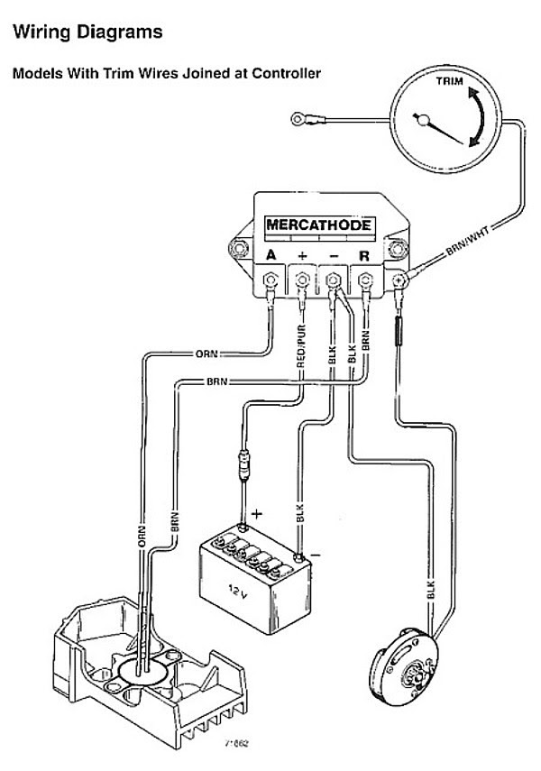
- Connections: Diagrams illustrate the precise electrical connections between components, specifying wire colors, terminal locations, and polarity.
- Power Source: Diagrams indicate the power source for the tilt and trim system, typically the boat’s battery.
- Grounding: Proper grounding is essential for the system’s functionality, and wiring diagrams show the grounding points for each component.
- Switch Operation: Diagrams explain the operation of the tilt and trim switches, including their positions and functions.
- Actuator Function: Diagrams provide insights into the operation of the tilt and trim actuators, which physically adjust the engine’s angle.
- Troubleshooting: Wiring diagrams are invaluable for troubleshooting electrical issues within the tilt and trim system, helping to identify faulty components or incorrect connections.
- Maintenance: Diagrams assist in regular maintenance tasks, such as inspecting and cleaning electrical connections to ensure optimal system performance.
These aspects of Mercruiser Tilt and Trim Switch Wiring Diagrams play a critical role in maintaining the safety and reliability of boating operations. By understanding and utilizing these diagrams, boaters and technicians can confidently manage the tilt and trim functions of their MerCruiser engines, ensuring optimal performance, handling, and efficiency on the water.
Components
In the context of Mercruiser Tilt and Trim Switch Wiring Diagrams, understanding the components involved is crucial. These diagrams provide a comprehensive overview of all electrical components, including switches, relays, solenoids, and actuators, which work together to control the tilt and trim functions of the engine. By identifying these components and their interconnections, boaters and technicians can effectively manage and troubleshoot the system.
Switches initiate the tilt and trim actions, sending signals to relays. Relays then activate solenoids, which in turn control the hydraulic actuators responsible for physically adjusting the engine’s angle. Each component plays a vital role in the overall functionality of the system. Without proper wiring and connections between these components, the tilt and trim system would not operate correctly.
For example, if the tilt switch malfunctions, the boat operator may be unable to raise or lower the engine, affecting the boat’s performance and safety. By utilizing Mercruiser Tilt and Trim Switch Wiring Diagrams, technicians can quickly identify the faulty switch and replace it, restoring the system’s functionality.
Overall, understanding the components involved in Mercruiser Tilt and Trim Switch Wiring Diagrams is essential for proper system operation, maintenance, and troubleshooting. These diagrams serve as a valuable resource for boaters and technicians, enabling them to manage the tilt and trim functions of their MerCruiser engines confidently.
Connections
In Mercruiser Tilt and Trim Switch Wiring Diagrams, precise electrical connections between components play a critical role in ensuring the proper functioning of the tilt and trim system. These diagrams illustrate the exact wire colors, terminal locations, and polarity, providing a roadmap for boaters and technicians to correctly connect and maintain the system.
Understanding these connections is vital because incorrect wiring can lead to malfunctioning of the tilt and trim system, affecting the boat’s performance and safety. For example, if the wires connecting the tilt switch to the relay are reversed, the tilt function may not work, leaving the boat operator unable to adjust the engine angle.
Wiring diagrams provide a visual representation of the electrical connections, making it easier to identify and troubleshoot any issues. By following the specified wire colors, terminal locations, and polarity, boaters and technicians can ensure that all components are correctly connected and operating as intended.
In practical applications, Mercruiser Tilt and Trim Switch Wiring Diagrams are essential for:
- Installation: Diagrams guide the proper installation of the tilt and trim system, ensuring all components are connected correctly.
- Maintenance: Diagrams assist in regular maintenance tasks, such as inspecting and cleaning electrical connections to prevent corrosion and ensure optimal system performance.
- Troubleshooting: Diagrams help identify faulty connections or components, allowing for quick and efficient troubleshooting to restore the system’s functionality.
In conclusion, understanding the precise electrical connections illustrated in Mercruiser Tilt and Trim Switch Wiring Diagrams is critical for the safe and reliable operation of the tilt and trim system. These diagrams provide a valuable resource for boaters and technicians to confidently manage and maintain their MerCruiser engines.
Power Source
In the context of Mercruiser Tilt And Trim Switch Wiring Diagrams, understanding the power source is critical because it provides the necessary electrical energy to operate the entire tilt and trim system. These diagrams clearly indicate the power source, typically the boat’s battery, and its connection to the system’s components.
The boat’s battery supplies the electrical power required for the tilt and trim system to function. Without a reliable power source, the switches, relays, solenoids, and actuators involved in the system would not be able to operate, rendering the tilt and trim functions inoperable.
For example, if the boat’s battery is discharged or malfunctions, the tilt and trim system will not receive the necessary power to operate, leaving the boat operator unable to adjust the engine angle. This could compromise the boat’s performance, handling, and safety, especially in situations where quick adjustments are needed.
Mercruiser Tilt And Trim Switch Wiring Diagrams play a vital role in ensuring the proper connection of the power source to the tilt and trim system. By following the diagrams, boaters and technicians can correctly connect the battery to the system, ensuring that all components receive the necessary electrical power.
Understanding the power source and its connection within Mercruiser Tilt And Trim Switch Wiring Diagrams is essential for:
- Safe operation: A reliable power source ensures that the tilt and trim system functions as intended, contributing to the overall safety of the boat and its occupants.
- Optimal performance: Adequate electrical power allows the tilt and trim system to operate efficiently, enabling boaters to adjust the engine angle for optimal performance in various conditions.
- Troubleshooting: In the event of system malfunctions, wiring diagrams help identify potential issues related to the power source, such as loose connections or faulty wiring.
In conclusion, the power source is a critical component of Mercruiser Tilt And Trim Switch Wiring Diagrams, providing the electrical energy necessary for the system’s operation. Understanding the power source and its connection enables boaters and technicians to maintain and troubleshoot the tilt and trim system effectively, ensuring safe and optimal performance on the water.
Grounding
In the context of Mercruiser Tilt And Trim Switch Wiring Diagrams, grounding plays a crucial role in ensuring the proper and safe operation of the tilt and trim system. These diagrams clearly indicate the grounding points for each component, providing a comprehensive guide for boaters and technicians to establish a reliable electrical connection to the boat’s electrical system.
- Connection to Boat’s Electrical System: Wiring diagrams show the connection points between the tilt and trim system and the boat’s electrical system, ensuring that the system receives the necessary electrical current to operate.
- Safety: Proper grounding helps prevent electrical shocks and other safety hazards by providing a safe path for electrical current to flow. Without proper grounding, electrical faults could occur, potentially leading to damage to the system or even personal injury.
- Component Protection: Grounding helps protect electrical components from damage caused by voltage spikes or electrical surges. By providing a low-resistance path to the boat’s electrical system, grounding helps dissipate excess electrical energy, safeguarding sensitive components.
- System Performance: Proper grounding ensures that electrical components receive a stable and consistent electrical current, contributing to the overall reliability and performance of the tilt and trim system.
Understanding grounding and its importance within Mercruiser Tilt And Trim Switch Wiring Diagrams is essential for several reasons. Firstly, it enables boaters and technicians to ensure the safe and proper installation of the tilt and trim system. Secondly, it helps in troubleshooting electrical issues by identifying potential grounding faults. Thirdly, it contributes to the overall longevity and reliability of the tilt and trim system by preventing damage to electrical components.
Switch Operation
Within the comprehensive framework of Mercruiser Tilt And Trim Switch Wiring Diagrams, the aspect of “Switch Operation” assumes great significance. These diagrams provide detailed explanations of how the tilt and trim switches operate, encompassing their positions and functions. Understanding these intricate details empowers boaters and technicians with the knowledge necessary for effective system management and troubleshooting.
- Switch Types and Positions: Wiring diagrams clearly illustrate the different types of tilt and trim switches, such as momentary or latching switches, and their respective positions on the boat’s control panel. Each switch’s position is carefully designed to optimize ergonomics and ease of use, ensuring intuitive control for the boat operator.
- Circuit Activation: Diagrams depict how the switches activate specific electrical circuits when engaged. This knowledge enables boaters to trace the flow of electrical signals and identify potential issues within the system. Understanding circuit activation is crucial for diagnosing and resolving electrical faults.
- Trim and Tilt Adjustments: Wiring diagrams provide insights into how the switches control the trim and tilt actuators, which physically adjust the engine’s angle. By comprehending the relationship between switch inputs and actuator outputs, boaters can fine-tune the boat’s performance and handling characteristics.
In summary, the “Switch Operation” aspect of Mercruiser Tilt And Trim Switch Wiring Diagrams equips boaters and technicians with a comprehensive understanding of how tilt and trim switches function. This knowledge empowers them to operate the system safely and efficiently, address any technical issues that may arise, and maintain optimal boat performance and handling.
Actuator Function
Within the comprehensive framework of Mercruiser Tilt And Trim Switch Wiring Diagrams, understanding actuator function is of paramount importance. Actuators serve as the physical mechanism responsible for adjusting the engine’s tilt and trim angles, playing a critical role in optimizing boat performance and handling. These diagrams provide invaluable insights into the operation of these actuators, enabling boaters and technicians to effectively manage and troubleshoot the tilt and trim system.
- Actuator Types: Wiring diagrams identify different types of actuators used in Mercruiser tilt and trim systems, such as hydraulic or electric actuators. Each type has unique characteristics, power requirements, and installation considerations.
- Actuator Control: Diagrams illustrate how tilt and trim switches send electrical signals to control the actuators. Understanding this signal flow is essential for diagnosing and resolving electrical issues within the system.
- Mechanical Operation: Diagrams provide insights into the mechanical operation of actuators, including how they convert electrical energy into physical movement to adjust the engine’s angle. This knowledge is crucial for troubleshooting mechanical problems and ensuring proper actuator operation.
- Actuator Maintenance: Wiring diagrams assist in routine maintenance tasks, such as inspecting and servicing actuators to prevent premature failure and ensure optimal system performance.
In summary, the “Actuator Function” aspect of Mercruiser Tilt And Trim Switch Wiring Diagrams equips boaters and technicians with a comprehensive understanding of how actuators operate within the tilt and trim system. This knowledge empowers them to maintain, troubleshoot, and optimize the system’s performance, ensuring a safe and enjoyable boating experience.
Troubleshooting
Electrical troubleshooting in the marine environment presents unique challenges, and the Mercruiser Tilt And Trim Switch Wiring Diagram plays a pivotal role in resolving issues within the tilt and trim system. These diagrams provide a comprehensive roadmap of the electrical connections, enabling boaters and technicians to systematically diagnose and rectify faults.
For instance, if the tilt or trim function becomes inoperable, the wiring diagram guides the user in tracing the electrical circuit from the switch to the actuator, identifying potential points of failure along the way. By systematically checking for loose connections, damaged wires, or faulty components, the diagram helps isolate the root cause of the problem.
Moreover, the diagram serves as a valuable reference for understanding the system’s normal operating parameters. By comparing actual voltage and resistance measurements to the specified values provided in the diagram, technicians can quickly assess whether a component is functioning within its intended range.
In summary, the Mercruiser Tilt And Trim Switch Wiring Diagram empowers boaters and technicians with the knowledge and tools to effectively troubleshoot electrical issues within the tilt and trim system. Its importance lies in providing a structured approach to fault identification, reducing downtime, and ensuring the safe and reliable operation of the boat.
Maintenance
Within the context of Mercruiser Tilt And Trim Switch Wiring Diagrams, the aspect of maintenance takes on great significance. These diagrams provide a comprehensive guide for boaters and technicians to perform regular maintenance tasks, ensuring the optimal performance and longevity of the tilt and trim system.
One critical aspect of maintenance is the inspection and cleaning of electrical connections. Over time, electrical connections can accumulate dirt, corrosion, or moisture, leading to reduced conductivity and potential system malfunctions. Wiring diagrams play a crucial role in identifying the location of all electrical connections within the tilt and trim system, allowing for thorough inspection and cleaning.
For example, the diagram may indicate the location of electrical connections at the switch panel, relays, actuators, and power source. By following the diagram, boaters and technicians can systematically inspect each connection, ensuring that they are clean, tight, and free of any signs of damage or corrosion.
Regular maintenance of electrical connections is essential for several reasons. Firstly, it helps prevent unexpected system failures by eliminating potential sources of electrical faults. Secondly, it contributes to the overall reliability and efficiency of the tilt and trim system, ensuring that it operates as intended when needed.
Furthermore, understanding the maintenance aspect of Mercruiser Tilt And Trim Switch Wiring Diagrams empowers boaters and technicians to proactively maintain their vessels, reducing the likelihood of costly repairs and downtime.
![[DIAGRAM] Mercruiser Tilt Trim Diagram](https://i0.wp.com/d3d71ba2asa5oz.cloudfront.net/32001220/images/wh-001b2.jpg?w=665&ssl=1)


Related Posts


