A Mag Lock Wiring Diagram guides the electrical installation to operate a magnetic lock. It outlines the connections of power sources, access controls, and the magnetic lock itself, ensuring secure building access.
Mag Lock Wiring Diagrams are crucial for efficient and reliable access control systems. They prevent short circuits, ensure proper power distribution, and optimize magnetic lock functionality. Wiring diagrams have driven the advancement of building security, enabling the integration of various access control components for a comprehensive security ecosystem.
This article delves into the intricacies of Mag Lock Wiring Diagrams, addressing their significance, best practices, and the latest technological advancements in access control systems.
Understanding the essential aspects of Mag Lock Wiring Diagrams is paramount to effectively plan, install, and maintain access control systems. Here are eight key aspects:
- Diagram Type: Wiring diagrams can be schematic, pictorial, or a combination, each providing varying levels of detail.
- Power Requirements: Diagrams specify the electrical specifications, including voltage, amperage, and power supply type.
- Lock Compatibility: Wiring diagrams ensure compatibility between the magnetic lock and the power supply.
- Access Control Integration: They guide the integration of access control devices, such as card readers and keypads, with the lock.
- Safety Features: Diagrams incorporate safety mechanisms, such as fail-safe or fail-secure modes, for emergency egress.
- Environmental Considerations: They account for environmental factors, such as weather conditions and temperature ranges, to ensure optimal performance.
- Maintenance and Troubleshooting: Wiring diagrams facilitate maintenance and troubleshooting by providing a clear roadmap of the system’s electrical connections.
- Code Compliance: Diagrams help ensure compliance with electrical codes and building regulations.
These aspects are interconnected and crucial for the proper functioning of Mag Lock Wiring Diagrams. They provide a comprehensive understanding of the system’s design, installation, and maintenance requirements, enabling efficient and secure access control.
Diagram Type
Mag Lock Wiring Diagrams come in three primary types: schematic, pictorial, and a hybrid combination. Each type serves a specific purpose and provides varying levels of detail to cater to different needs and skill levels.
-
Schematic Diagrams
Schematic diagrams depict the electrical connections using symbols and lines, focusing on the logical flow of the system. They are commonly used by experienced electricians and engineers for their concise and standardized representation. -
Pictorial Diagrams
Pictorial diagrams utilize images and symbols to represent the physical layout of the system. They are intuitive and easy to understand, making them ideal for non-technical personnel involved in installation and maintenance. -
Combination Diagrams
Combination diagrams combine elements of both schematic and pictorial diagrams, providing a comprehensive view of the system. They are beneficial for complex systems where a mix of technical and non-technical personnel may be involved.
The choice of diagram type depends on the specific requirements of the project, the skill level of the installer, and the level of detail needed for troubleshooting and maintenance. Understanding the differences between these diagram types enables effective communication and ensures accurate installation and operation of Mag Lock Wiring Diagrams.
Power Requirements
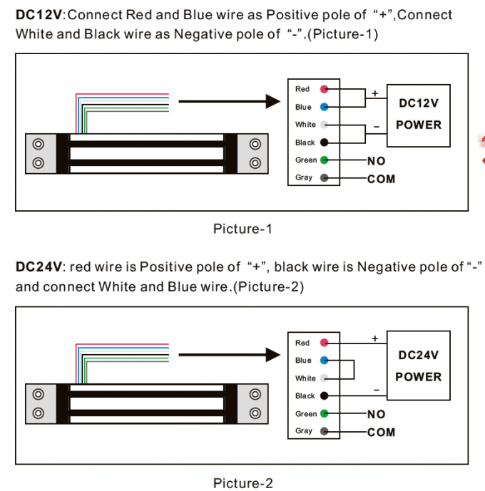
In Mag Lock Wiring Diagrams, specifying the electrical specifications, including voltage, amperage, and power supply type, is crucial for the proper functioning and safety of the system. These specifications determine the compatibility between the magnetic lock and the power supply, ensuring optimal performance and preventing damage to the components.
For instance, a magnetic lock rated for 12 volts DC would require a power supply that provides 12 volts DC. Using an incorrect power supply voltage can lead to insufficient power, malfunction, or even damage to the lock. Similarly, the amperage rating of the lock determines the amount of current it can draw, and the power supply must be able to provide sufficient amperage to operate the lock effectively.
Understanding the power requirements and correctly specifying them in the Mag Lock Wiring Diagram is essential for reliable access control. It prevents potential hazards, ensures the longevity of the system, and contributes to the overall security of the premises.
Lock Compatibility
In the realm of Mag Lock Wiring Diagrams, ensuring compatibility between the magnetic lock and the power supply is a pivotal consideration. It forms the cornerstone of a well-functioning access control system, preventing operational issues, safety hazards, and premature component failure.
- Voltage and Current Matching: Wiring diagrams specify the voltage and current requirements of the magnetic lock, ensuring that the power supply provides the correct electrical parameters. Mismatched voltage or current can lead to insufficient power, overheating, or even damage to the lock.
- Power Supply Capacity: The diagram must account for the power consumption of the magnetic lock and any additional devices connected to the power supply. An underpowered supply can result in voltage drops, causing the lock to malfunction or fail.
- Lock Type Compatibility: Different types of magnetic locks, such as fail-safe and fail-secure, have specific power requirements. The wiring diagram must ensure that the power supply is compatible with the lock’s operating mode.
- Environmental Considerations: In outdoor applications, the power supply must be rated for the expected environmental conditions, such as temperature fluctuations and moisture resistance. Improperly rated power supplies can lead to premature failure or safety hazards.
Addressing lock compatibility in Mag Lock Wiring Diagrams is crucial for a secure and reliable access control system. By carefully considering these aspects, system designers and installers can ensure that the magnetic lock and power supply work seamlessly together, providing optimal performance and longevity.
Access Control Integration
In the context of Mag Lock Wiring Diagrams, access control integration plays a critical role in establishing a comprehensive security system. It ensures seamless communication between access control devices, such as card readers and keypads, and the magnetic lock, enabling controlled access to secure areas.
The Mag Lock Wiring Diagram outlines the electrical connections and protocols required to integrate these devices. It specifies the wiring layout, power requirements, and communication interfaces to ensure proper functionality and secure operation. Without proper access control integration, the magnetic lock would operate independently, limiting its effectiveness as a security measure.
Real-life examples of access control integration within Mag Lock Wiring Diagrams can be found in various applications, including office buildings, residential complexes, and data centers. In an office building, for instance, card readers integrated with the magnetic lock allow authorized employees to enter restricted areas, while preventing unauthorized access.
Understanding the connection between access control integration and Mag Lock Wiring Diagrams is crucial for system designers, installers, and security professionals. It enables them to create robust and reliable access control systems that meet specific security requirements, enhancing the overall safety and security of the premises.
Safety Features
In the context of Mag Lock Wiring Diagrams, safety features play a paramount role in ensuring reliable and secure access control systems. These diagrams incorporate safety mechanisms, such as fail-safe or fail-secure modes, to address emergency egress scenarios effectively.
Fail-safe and fail-secure modes are two primary safety mechanisms implemented in Mag Lock Wiring Diagrams. Fail-safe mode ensures that the magnetic lock unlocks in the event of a power failure, allowing for quick and easy egress from secure areas. This is crucial in emergency situations, such as fire alarms or power outages, where immediate evacuation is necessary.
On the other hand, fail-secure mode keeps the magnetic lock engaged in the event of a power failure, preventing unauthorized access to secure areas. It is commonly used in high-security applications, such as data centers or vaults, where maintaining the integrity of the secured space is critical.
Real-life examples of safety features within Mag Lock Wiring Diagrams can be found in various industries and applications. In hospitals, for instance, fail-safe mechanisms are incorporated to ensure that emergency exits remain accessible during power outages, enabling patients and staff to evacuate safely.
Understanding the significance of safety features in Mag Lock Wiring Diagrams is essential for system designers and installers. These mechanisms provide added protection and peace of mind, ensuring that access control systems operate reliably and effectively, even in emergency situations.
Environmental Considerations
In the context of Mag Lock Wiring Diagrams, environmental considerations play a critical role in ensuring the reliable operation and longevity of access control systems. These diagrams account for environmental factors, such as weather conditions and temperature ranges, to guarantee optimal performance in diverse operating environments.
Real-life examples of environmental considerations within Mag Lock Wiring Diagrams can be found in various applications. Outdoor installations, for instance, require weather-resistant enclosures to protect the electrical components from moisture, dust, and extreme temperatures. This ensures the system’s functionality in all weather conditions, preventing malfunctions or premature failure.
Understanding the connection between environmental considerations and Mag Lock Wiring Diagrams is essential for system designers and installers. By incorporating appropriate measures to address environmental factors, they can ensure that access control systems operate reliably and effectively, even in challenging environments.
Maintenance and Troubleshooting
Within the context of Mag Lock Wiring Diagrams, maintenance and troubleshooting are crucial aspects for ensuring the longevity and reliability of access control systems. Wiring diagrams serve as invaluable tools in this regard, providing a comprehensive roadmap of the system’s electrical connections, enabling efficient maintenance and troubleshooting procedures.
- Simplified Troubleshooting: Wiring diagrams break down the system’s electrical connections into a logical and easy-to-understand format. This simplified representation aids technicians in quickly identifying faults, reducing troubleshooting time and minimizing system downtime.
- Precise Component Identification: Wiring diagrams clearly label and identify each component within the system, including the magnetic lock, power supply, access control devices, and any additional peripherals. This precise identification simplifies maintenance tasks, allowing technicians to easily locate and replace faulty components.
- Real-Time Monitoring: In advanced Mag Lock Wiring Diagrams, real-time monitoring capabilities may be integrated. These diagrams incorporate sensors and monitoring devices that provide real-time data on the system’s performance, enabling proactive maintenance and preventing unexpected failures.
- Historical Troubleshooting Records: Wiring diagrams serve as a valuable historical record of troubleshooting and maintenance activities. Technicians can refer to these diagrams to track recurring issues and identify potential areas for improvement, optimizing the system’s overall performance and reliability.
In summary, Mag Lock Wiring Diagrams play a pivotal role in maintaining and troubleshooting access control systems. They provide a clear roadmap of the system’s electrical connections, simplifying troubleshooting, facilitating component identification, enabling real-time monitoring, and serving as historical troubleshooting records. By leveraging these diagrams, technicians can ensure the optimal performance, reliability, and longevity of access control systems.
Code Compliance
In the context of Mag Lock Wiring Diagrams, code compliance is of paramount importance. These diagrams serve as blueprints that guide the installation and maintenance of access control systems, ensuring adherence to established electrical codes and building regulations. By following code-compliant wiring diagrams, system designers and installers can mitigate safety hazards, maintain system reliability, and avoid legal complications.
- Electrical Safety: Wiring diagrams ensure that electrical installations comply with safety standards, preventing electrical fires, shocks, and other hazards. They specify proper wire sizing, circuit protection, and grounding techniques, minimizing the risk of electrical accidents.
- System Reliability: Code-compliant wiring diagrams promote system reliability by incorporating best practices for load balancing, voltage regulation, and surge protection. This reduces the likelihood of system failures, ensures consistent performance, and extends the lifespan of access control components.
- Legal Compliance: Adhering to electrical codes and building regulations is a legal requirement in most jurisdictions. Wiring diagrams provide documentation that demonstrates compliance, protecting system owners from legal liability in the event of accidents or inspections.
- Insurance Coverage: Insurance companies may require code-compliant wiring diagrams as a condition for coverage. These diagrams provide evidence of proper installation and maintenance, ensuring that insurance claims are processed smoothly in the event of damage or loss.
In summary, Mag Lock Wiring Diagrams play a crucial role in ensuring code compliance. By adhering to established standards and regulations, these diagrams promote electrical safety, enhance system reliability, meet legal requirements, and facilitate insurance coverage. System designers, installers, and building owners can leverage code-compliant wiring diagrams to create safe, reliable, and legally compliant access control systems.


Related Posts


