A Lux thermostat wiring diagram is a detailed schematic that outlines the electrical connections between a Lux thermostat and its associated HVAC system. It provides a clear visual representation of the wires and terminals involved, enabling proper installation, maintenance, and troubleshooting.
The wiring diagram serves as a vital reference guide for technicians, homeowners, and DIY enthusiasts alike. It ensures that the thermostat is correctly wired to the heating, cooling, and ventilation equipment for optimal performance and system longevity. Moreover, it allows for efficient diagnosis and resolution of any electrical issues that may arise.
Throughout the evolution of thermostat technology, wiring diagrams have played a crucial role. Early thermostats relied on simple on/off switching mechanisms. As thermostats became more sophisticated, integrating programmable settings, multiple stages of heating and cooling, and wireless communication, their wiring diagrams grew more intricate. This has necessitated the development of standardized wiring conventions and easy-to-follow diagrams to facilitate their seamless integration with various HVAC systems.
The Lux thermostat wiring diagram encompasses various essential aspects that contribute to its functionality and significance within HVAC systems. Understanding these key aspects is vital for proper installation, maintenance, and troubleshooting of Lux thermostats.
- Electrical Connections: The wiring diagram outlines the specific electrical connections between the thermostat, power source, and HVAC equipment, ensuring proper functionality.
- Terminal Identification: It provides clear identification of the terminals on the thermostat, enabling accurate wire connections.
- Compatibility: The diagram specifies the compatibility of the thermostat with different HVAC systems, including furnaces, air conditioners, and heat pumps.
- System Configuration: It guides the configuration of the thermostat based on the specific HVAC system, such as single-stage, multi-stage, or heat pump systems.
- Troubleshooting: The wiring diagram serves as a troubleshooting tool, helping identify and resolve electrical issues or connection problems.
- Safety: Proper wiring ensures the safe operation of the thermostat and HVAC system, preventing electrical hazards.
- Efficiency: Correct wiring optimizes the performance of the HVAC system, resulting in improved energy efficiency and reduced operating costs.
- Customization: The diagram allows for customization of the thermostat’s settings and features, tailoring it to specific user preferences and system requirements.
- Compliance: Adherence to the wiring diagram ensures compliance with electrical codes and safety standards.
These aspects collectively contribute to the effectiveness and reliability of Lux thermostat wiring diagrams. They provide a comprehensive guide for technicians and homeowners alike, enabling successful installation, maintenance, and troubleshooting of Lux thermostats within HVAC systems.
Electrical Connections
Electrical connections in a Lux thermostat wiring diagram play a crucial role in establishing a functional link between the thermostat, power source, and HVAC equipment. These connections are meticulously detailed in the wiring diagram, ensuring proper operation, efficient communication, and optimal performance of the entire HVAC system.
- Power Supply: The wiring diagram specifies the power requirements of the thermostat, including voltage and current, and outlines the connections to the power source. This ensures a reliable and stable power supply for the thermostat’s operation.
- System Integration: The diagram provides a roadmap for connecting the thermostat to the HVAC equipment, such as the furnace, air conditioner, or heat pump. It identifies the terminals on the thermostat and equipment that need to be connected for proper communication and control.
- Signal Transmission: The wiring diagram outlines the signal pathways between the thermostat and the HVAC equipment. These signals enable the thermostat to send commands to adjust temperature settings, fan speed, or mode of operation to the HVAC system, ensuring precise control over the indoor environment.
- Safety Features: The diagram also incorporates safety features, such as overcurrent protection and grounding connections. These connections safeguard the thermostat, HVAC equipment, and users from electrical hazards, ensuring reliable and safe operation.
In summary, the electrical connections in a Lux thermostat wiring diagram serve as the backbone of the HVAC system. By providing a clear and comprehensive guide for establishing proper connections between the thermostat, power source, and HVAC equipment, the wiring diagram ensures efficient communication, optimal performance, and adherence to safety standards.
Terminal Identification
In the context of a Lux thermostat wiring diagram, terminal identification holds paramount importance. It serves as the cornerstone for establishing precise and secure electrical connections between the thermostat and the HVAC system’s components, ensuring seamless communication and optimal performance.
The wiring diagram clearly labels each terminal on the thermostat, corresponding to specific functions such as power supply, heating, cooling, fan operation, and auxiliary connections. This systematic identification enables accurate wire connections, eliminating the risk of miswiring and potential electrical hazards.
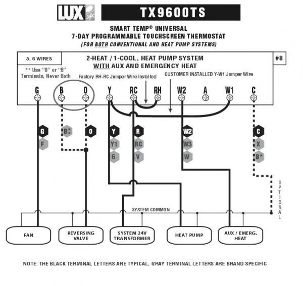
For instance, consider the terminal labeled “RH” (Red Heat). This terminal must be connected to the red wire from the furnace or heat pump to establish the heating circuit. Proper identification of this terminal ensures the thermostat can effectively send signals to activate the heating system when necessary.
Similarly, the terminal marked “C” (Common) serves as the central connection point for the thermostat’s power supply. Accurate identification of this terminal ensures a reliable power connection, enabling the thermostat to function correctly.
In summary, terminal identification within a Lux thermostat wiring diagram plays a critical role in ensuring accurate wire connections, preventing miswiring, and guaranteeing the safe and efficient operation of the HVAC system.
Compatibility
Within the context of a Lux thermostat wiring diagram, compatibility plays a critical role in ensuring seamless integration with various HVAC systems. The diagram serves as a guide for selecting the appropriate thermostat model and wiring configuration based on the specific HVAC system installed.
Compatibility considerations arise due to differences in electrical requirements, communication protocols, and system configurations among different HVAC systems. For instance, a thermostat designed for a furnace may not be compatible with a heat pump system without proper wiring adaptations.
The Lux thermostat wiring diagram addresses these compatibility issues by clearly specifying the supported HVAC systems and their corresponding wiring configurations. This information enables users to select the correct thermostat model and wire it appropriately, ensuring optimal performance and efficient system operation.
Real-life examples further illustrate the importance of compatibility in Lux thermostat wiring diagrams. Consider a scenario where a user attempts to install a Lux thermostat designed for a furnace in a heat pump system. Without proper compatibility considerations, the thermostat may not be able to communicate effectively with the heat pump, leading to improper temperature control and potential system malfunctions.
Understanding the compatibility specifications in a Lux thermostat wiring diagram is essential for preventing such issues and ensuring a successful installation. It empowers users to make informed decisions regarding thermostat selection and wiring, maximizing the efficiency and reliability of their HVAC systems.
System Configuration
Within the context of a Lux thermostat wiring diagram, system configuration holds immense importance as it ensures optimal compatibility and performance between the thermostat and the HVAC system. The wiring diagram meticulously outlines the necessary steps to configure the thermostat based on the specific type of HVAC system installed, such as single-stage, multi-stage, or heat pump systems.
- HVAC System Compatibility: The wiring diagram specifies the compatibility of the thermostat with different HVAC systems. This information helps users select the appropriate thermostat model and wire it correctly, ensuring seamless integration and efficient operation.
- Single-Stage Systems: For single-stage HVAC systems, the wiring diagram provides clear instructions on connecting the thermostat to the heating and cooling equipment. It ensures proper control of the system, allowing for basic temperature regulation.
- Multi-Stage Systems: In the case of multi-stage HVAC systems, the wiring diagram guides the configuration of the thermostat to control multiple stages of heating or cooling. This enables more precise temperature control and improved energy efficiency.
- Heat Pump Systems: For heat pump systems, the wiring diagram provides detailed instructions on wiring the thermostat to manage both heating and cooling operations. It ensures efficient heat transfer and maintains comfortable indoor temperatures.
Understanding and adhering to the system configuration guidelines in a Lux thermostat wiring diagram is crucial for ensuring proper functionality, maximizing energy efficiency, and enhancing comfort levels within the living space. By providing clear and precise instructions, the wiring diagram empowers users to confidently install and configure their thermostats, optimizing the performance of their HVAC systems.
Troubleshooting
Within the context of a Lux thermostat wiring diagram, troubleshooting plays a crucial role in maintaining optimal system performance and ensuring comfort within the living space. The wiring diagram serves as an invaluable tool for identifying and resolving electrical issues or connection problems that may arise during installation, operation, or over time.
Troubleshooting capabilities stem from the comprehensive nature of the wiring diagram. It provides a detailed roadmap of the electrical connections within the thermostat and its interface with the HVAC system. This allows technicians and homeowners alike to systematically inspect the wiring, identify any discrepancies or faults, and determine the root cause of any malfunctions.
Real-life examples further illustrate the practical significance of troubleshooting within a Lux thermostat wiring diagram. Consider a scenario where the thermostat fails to control the heating system, resulting in an uncomfortably cold indoor environment. By referring to the wiring diagram, a technician can trace the electrical connections, check for loose wires or faulty components, and pinpoint the exact source of the problem. This enables prompt repairs or replacements, restoring the system to normal operation.
The ability to troubleshoot using the wiring diagram empowers users to address minor issues , saving time and expenses on professional service calls. It also promotes a deeper understanding of the thermostat’s functionality and the HVAC system’s operation, fostering self-reliance and proactive maintenance.
In summary, the troubleshooting capabilities embedded within a Lux thermostat wiring diagram are essential for maintaining a well-functioning HVAC system. By providing a clear and comprehensive guide to the electrical connections, the wiring diagram empowers users to diagnose and resolve issues effectively, ensuring optimal comfort and energy efficiency within their living spaces.
Safety
Within the context of a Lux Thermostat Wiring Diagram, safety takes paramount importance, as proper wiring practices are crucial for ensuring the safe operation of both the thermostat and the connected HVAC system. By adhering to the guidelines outlined in the wiring diagram, users can minimize electrical hazards, prevent system malfunctions, and maintain a comfortable and secure indoor environment.
- Electrical Insulation: The wiring diagram specifies the use of properly insulated wires throughout the system. This prevents electrical shock and short circuits, ensuring the safety of users and protecting the thermostat and HVAC components from damage.
- Polarity Compliance: The diagram emphasizes the importance of maintaining correct polarity when connecting wires to the thermostat and HVAC equipment. Reversing polarity can lead to equipment malfunctions, potential damage, and even electrical fires.
- Grounding: Proper grounding, as outlined in the wiring diagram, provides a safe path for electrical current to flow in case of a fault. This prevents stray voltage from accumulating on the thermostat or HVAC system, reducing the risk of electrical shocks or damage.
- Overcurrent Protection: The wiring diagram may incorporate overcurrent protection devices, such as fuses or circuit breakers, to safeguard the thermostat and HVAC system from electrical overloads. These devices interrupt the electrical circuit if excessive current flows, preventing damage to components and potential fire hazards.
By incorporating these safety measures into the wiring diagram, Lux ensures that its thermostats can be installed and operated safely and efficiently. Adhering to the specified wiring practices minimizes the risk of electrical hazards, protects users and property, and contributes to the overall reliability and longevity of the HVAC system.
Efficiency
Within the context of a Lux Thermostat Wiring Diagram, achieving optimal energy efficiency is paramount. Correct wiring practices, as outlined in the diagram, play a crucial role in maximizing the performance of the HVAC system, leading to reduced energy consumption and lower operating costs.
The Lux Thermostat Wiring Diagram serves as a roadmap for establishing efficient electrical connections between the thermostat and the HVAC equipment. By following the specified wiring configurations, users can ensure that the thermostat accurately controls the heating and cooling system, optimizing energy usage.
For instance, proper wiring ensures that the thermostat correctly senses the indoor temperature and adjusts the HVAC system accordingly. This prevents unnecessary heating or cooling cycles, reducing energy waste. Additionally, the diagram provides guidance on optimizing fan settings, ensuring efficient air circulation and temperature distribution throughout the living space.
In summary, the Lux Thermostat Wiring Diagram empowers users to create an energy-efficient HVAC system by providing clear instructions for correct wiring practices. Adhering to these guidelines maximizes the efficiency of the thermostat and the entire HVAC system, resulting in reduced energy consumption, lower operating costs, and a more comfortable indoor environment.
Customization
Within the comprehensive framework of a Lux Thermostat Wiring Diagram, customization emerges as a crucial aspect, empowering users to tailor their thermostats to specific preferences and system requirements. This flexibility enhances the user experience, optimizes system performance, and caters to diverse scenarios.
- Personalized Temperature Control: The wiring diagram provides options for customizing temperature settings, allowing users to establish desired comfort levels. This includes adjusting heating and cooling setpoints, programming schedules, and enabling energy-saving modes.
- System Compatibility: The diagram guides users in configuring the thermostat for compatibility with various HVAC systems, including furnaces, heat pumps, and air conditioners. This ensures seamless integration and optimal performance across different equipment types.
- Advanced Features: The wiring diagram enables access to advanced thermostat features, such as geofencing, remote control, and smart home integration. These features enhance convenience, energy efficiency, and remote management capabilities.
- Multi-Zone Control: For homes with multiple heating and cooling zones, the wiring diagram provides instructions for setting up multi-zone control. This allows users to independently manage temperatures in different rooms or areas, maximizing comfort and energy efficiency.
In summary, the customization capabilities outlined in the Lux Thermostat Wiring Diagram empower users to tailor their thermostats to their unique needs and system configurations. By providing flexible wiring options and detailed instructions, the diagram ensures that the thermostat operates optimally, delivering personalized comfort, enhanced efficiency, and seamless integration with the HVAC system.
Compliance
Within the context of a Lux Thermostat Wiring Diagram, compliance holds paramount importance as it ensures adherence to established electrical codes and safety standards. By following the guidelines outlined in the diagram, users can guarantee the safe and efficient operation of their HVAC systems, minimizing potential hazards and ensuring the well-being of occupants.
- Electrical Safety: The wiring diagram incorporates safety measures that comply with electrical codes, such as proper grounding, overcurrent protection, and the use of insulated wires. These measures prevent electrical shocks, short circuits, and potential fires, ensuring a safe operating environment.
- Code Compliance: Adhering to the wiring diagram helps users meet local electrical codes and regulations. This ensures that the thermostat installation complies with building standards, which are in place to safeguard against electrical hazards and ensure the proper functioning of HVAC systems.
- Insurance Coverage: In the event of an insurance claim related to electrical issues, compliance with the wiring diagram can serve as proof that the thermostat was installed according to safety standards. This can help homeowners or businesses avoid disputes and ensure coverage for potential damages.
- Professional Standards: The wiring diagram aligns with industry best practices and professional standards for thermostat installation. Following these guidelines demonstrates a commitment to quality workmanship and ensures that the thermostat is installed and wired correctly, maximizing its lifespan and performance.
In conclusion, compliance with the Lux Thermostat Wiring Diagram is not merely a matter of following instructions; it is a crucial aspect that ensures the safety and reliability of the HVAC system. By adhering to the specified wiring practices, users can create a secure and efficient indoor environment, minimize risks, and maintain a comfortable living space.


Related Posts


