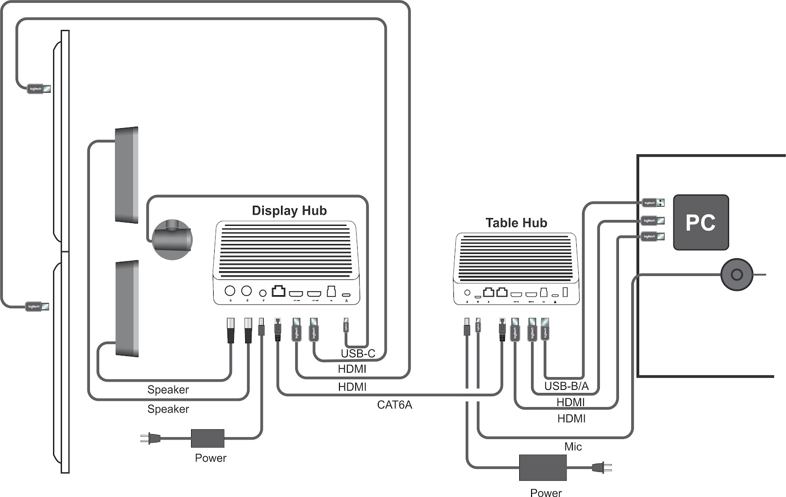
A Logitech Rally Plus Wiring Diagram provides a detailed visual representation of the electrical connections necessary to set up and use the Logitech Rally Plus video conferencing system. It outlines the specific cables, connectors, and ports required to establish connections between the various components, including the camera, microphone, speaker, and control unit.
Understanding the wiring diagram is crucial for ensuring proper system functionality and avoiding any technical issues. It enables installers and users to correctly connect the cables and configure the settings to achieve the desired audio and video performance. Benefits of using the wiring diagram include seamless system integration, reduced installation time, and enhanced reliability.
Key historical developments in wiring diagrams for Logitech products include advancements in connection technologies and the introduction of easy-to-follow graphical representations. These improvements have made the installation and setup process more user-friendly and accessible, allowing for a wider adoption of the Rally Plus system. The wiring diagram serves as a foundational resource for understanding the system’s electrical connectivity and is essential for ensuring optimal performance in various meeting room environments.
The Logitech Rally Plus Wiring Diagram plays a critical role in ensuring the seamless installation, configuration, and operation of the Logitech Rally Plus video conferencing system. Understanding the various aspects of the wiring diagram is essential for system integrators, IT professionals, and users alike.
- Connectivity: The wiring diagram outlines the specific cables and connectors required to establish connections between the camera, microphone, speaker, and control unit, ensuring optimal signal transmission.
- Power: It provides information on the power requirements and connections for each component, ensuring that they receive the necessary power for proper operation.
- Signal Flow: The diagram illustrates the signal flow between the components, including audio and video signals, helping users troubleshoot and optimize system performance.
- Network Configuration: It provides guidance on network connectivity and configuration, allowing users to integrate the Rally Plus system into their existing network infrastructure.
- Expansion: The wiring diagram may include information on expansion options, such as connecting additional microphones or cameras, allowing users to customize the system to meet their specific needs.
- Troubleshooting: The diagram serves as a valuable resource for troubleshooting connection and performance issues, helping users identify and resolve problems quickly.
- Compliance: By following the wiring diagram, users can ensure that the Rally Plus system is installed and configured in accordance with industry standards and safety regulations.
- Documentation: The wiring diagram is an essential part of the Rally Plus system documentation, providing a permanent record of the system’s electrical connections for future reference or maintenance.
These aspects of the Logitech Rally Plus Wiring Diagram are interconnected and equally important for the successful deployment and operation of the video conferencing system. By understanding and adhering to the wiring diagram, users can maximize system performance, ensure reliability, and minimize downtime, ultimately enhancing the overall video conferencing experience.
Connectivity
The Logitech Rally Plus Wiring Diagram serves as a comprehensive guide for establishing optimal connectivity between the various components of the Logitech Rally Plus video conferencing system. It outlines the specific cables and connectors required for each connection, ensuring that audio and video signals are transmitted reliably and efficiently. Without a clear understanding of the connectivity requirements, users may encounter issues such as poor audio quality, video dropouts, or system malfunctions.
Proper connectivity is a critical component of a successful Logitech Rally Plus deployment. By following the wiring diagram, users can ensure that the system is configured correctly, minimizing the risk of signal degradation or interference. For example, the diagram specifies the use of high-quality HDMI cables for video transmission and shielded Ethernet cables for network connectivity, which are essential for maintaining signal integrity and preventing data loss.
Understanding the connectivity aspect of the Logitech Rally Plus Wiring Diagram is crucial for achieving seamless video conferencing experiences. It enables users to troubleshoot and resolve connectivity issues quickly, ensuring that meetings are conducted without any technical disruptions. Furthermore, the diagram provides a valuable reference for system expansion or reconfiguration, allowing users to adapt the system to changing needs or room layouts.
Power
Within the Logitech Rally Plus Wiring Diagram, the aspect of power plays a crucial role in ensuring the reliable operation of all system components. It outlines the specific power requirements and connections for each component, including the camera, microphone, speaker, and control unit. Understanding and adhering to these power specifications are essential for maintaining system stability, preventing damage to components, and achieving optimal performance.
- Power Sources: The wiring diagram specifies the appropriate power sources for each component, whether it be AC power via a wall outlet or PoE (Power over Ethernet). This information is critical for selecting the correct power adapters and ensuring that the components receive the necessary voltage and amperage.
- Power Consumption: The diagram provides data on the power consumption of each component, enabling users to calculate the total power requirements for the system and ensure that the power supply is adequate. This information is particularly important in scenarios where multiple components are connected to a single power source.
- Cable Specifications: The wiring diagram specifies the type and gauge of cables required for power connections. This information ensures that the cables can handle the current draw of the components and minimize power loss. Proper cable selection is crucial for maintaining system reliability and preventing overheating.
- Grounding: The diagram may also include grounding requirements for the components, which are essential for protecting the system from electrical hazards and ensuring reliable operation. Grounding helps to dissipate static electricity and prevent electrical noise, which can interfere with system performance.
By understanding and following the power specifications outlined in the Logitech Rally Plus Wiring Diagram, users can ensure that the system is powered correctly, minimize the risk of component damage, and optimize system performance. Proper power connections are a fundamental aspect of a successful video conferencing deployment, enabling seamless communication and collaboration.
Signal Flow
Within the context of the Logitech Rally Plus Wiring Diagram, understanding the signal flow is crucial for ensuring that audio and video signals are transmitted and processed correctly throughout the system. The diagram illustrates the signal flow between the various components, providing valuable insights for troubleshooting and optimizing system performance.
- Signal Path Identification: The wiring diagram allows users to identify the signal path for both audio and video signals, from the input sources (e.g., camera, microphone) to the output devices (e.g., speaker, display). This information helps in troubleshooting signal issues, such as audio dropouts or video freezing, by enabling users to isolate the affected component or connection.
- Signal Format Conversion: The diagram may also indicate where signal format conversion occurs within the system. For example, the camera may output an HDMI signal, which is then converted to USB for transmission to the computer. Understanding these conversion points is important for ensuring that the signals are compatible and maintaining optimal signal quality.
- Signal Routing and Control: The wiring diagram provides insights into how signals are routed and controlled within the system. It illustrates how the control unit manages signal switching, volume adjustment, and other functions. This information is crucial for configuring the system to meet the specific requirements of the meeting space and ensuring seamless transitions between different signal sources.
- Signal Latency: The diagram can help users understand the potential sources of signal latency in the system. By identifying the components and connections that introduce latency, users can take steps to minimize it, ensuring real-time communication and minimizing interruptions during video conferences.
By understanding the signal flow illustrated in the Logitech Rally Plus Wiring Diagram, users can optimize system performance, troubleshoot issues effectively, and ensure a seamless video conferencing experience. The diagram serves as a valuable tool for system integrators, IT professionals, and users alike, providing insights into the system’s signal handling capabilities and enabling them to configure and maintain the system for optimal performance.
Network Configuration
Network configuration is a critical aspect of the Logitech Rally Plus Wiring Diagram as it provides detailed guidance on connecting the Rally Plus system to a network. It outlines the necessary steps for configuring network settings, assigning IP addresses, and establishing network connectivity for optimal performance and functionality. Without proper network configuration, the Rally Plus system would be unable to communicate with other devices on the network, limiting its functionality and preventing users from accessing its features remotely.
A real-life example of network configuration within the Logitech Rally Plus Wiring Diagram is the configuration of the Rally Plus camera. The diagram specifies the network settings that need to be configured on the camera, including the IP address, subnet mask, and default gateway. By following these instructions, users can ensure that the camera is properly integrated into the network and can be accessed and controlled remotely.
Understanding the relationship between network configuration and the Logitech Rally Plus Wiring Diagram is essential for system integrators, IT professionals, and users alike. Proper network configuration enables users to:
- Connect the Rally Plus system to their existing network infrastructure, allowing for remote access and control.
- Configure security settings to protect the system from unauthorized access and cyber threats.
- Troubleshoot network connectivity issues, ensuring optimal performance and minimizing downtime.
- Integrate the Rally Plus system with other network-enabled devices and applications, such as video conferencing software and cloud-based services.
In conclusion, network configuration plays a vital role in the successful deployment and operation of the Logitech Rally Plus video conferencing system. By understanding the guidance provided in the Logitech Rally Plus Wiring Diagram, users can effectively configure the system’s network settings, ensuring seamless integration, optimal performance, and enhanced collaboration capabilities.
Expansion
Within the comprehensive Logitech Rally Plus Wiring Diagram, the aspect of expansion plays a crucial role in adapting the system to meet the unique requirements of different meeting spaces and scenarios. It provides detailed information on the options for expanding the system’s capabilities through the addition of various components, ensuring that users can tailor the solution to their specific needs.
- Additional Microphones: The wiring diagram may include instructions on connecting additional microphones to the Rally Plus system, allowing users to enhance the audio pickup range and improve sound quality in larger meeting rooms or complex acoustic environments. This expansion option ensures that all participants can be heard clearly, facilitating effective communication and collaboration.
- Additional Cameras: The diagram may also provide guidance on connecting multiple cameras to the Rally Plus system, enabling users to capture a wider field of view or create multi-camera setups for more dynamic and engaging video conferencing experiences. This expansion option is particularly valuable in large meeting rooms or scenarios where multiple presenters or participants need to be visible.
- External Speakers: The wiring diagram may include information on connecting external speakers to the Rally Plus system, allowing users to enhance the audio output and provide a more immersive sound experience for participants. This expansion option is beneficial in larger rooms or scenarios where the built-in speakers may not provide sufficient volume or sound quality.
- Third-Party Devices: The diagram may also provide instructions on integrating third-party devices, such as PTZ (pan-tilt-zoom) cameras or audio mixers, into the Rally Plus system. This expansion option offers flexibility and customization, allowing users to incorporate specialized equipment to meet specific requirements, such as capturing high-quality video of a whiteboard or mixing multiple audio sources.
The expansion options outlined in the Logitech Rally Plus Wiring Diagram empower users to adapt the system to their unique needs, ensuring optimal performance and a tailored video conferencing experience. By understanding the expansion capabilities and following the wiring instructions, users can create customized solutions that meet the specific requirements of their meeting spaces and enhance collaboration outcomes.
Troubleshooting
Within the context of the Logitech Rally Plus Wiring Diagram, troubleshooting plays a pivotal role in ensuring the smooth operation and optimal performance of the video conferencing system. The diagram provides a comprehensive visual representation of the system’s electrical connections, enabling users to identify and resolve connection and performance issues efficiently.
-
Connection Verification:
The wiring diagram allows users to verify the physical connections between the various components of the Rally Plus system, including the camera, microphone, speaker, and control unit. By checking for loose or disconnected cables, users can ensure that the system is properly connected and that signals are transmitted reliably. -
Signal Tracing:
The diagram serves as a valuable tool for tracing signal flow throughout the system. By understanding the signal path, users can identify potential bottlenecks or points of failure, enabling them to isolate and resolve issues related to audio or video quality. -
Power Troubleshooting:
The wiring diagram provides insights into the power requirements and connections for each component. This information helps users identify potential power issues, such as insufficient power supply or faulty power adapters, and take corrective actions to ensure that the system receives adequate power. -
Grounding Verification:
Proper grounding is crucial for eliminating electrical noise and ensuring stable system operation. The wiring diagram indicates the grounding points for each component, allowing users to verify that the system is properly grounded and that ground loops are avoided.
Understanding the troubleshooting aspect of the Logitech Rally Plus Wiring Diagram empowers users to maintain the system’s functionality and performance. By utilizing the diagram to identify and resolve connection and performance issues, users can minimize downtime, ensure seamless video conferencing experiences, and maximize the value of their investment in the Logitech Rally Plus system.
Compliance
The Logitech Rally Plus Wiring Diagram serves as a critical resource for ensuring compliance with industry standards and safety regulations. By adhering to the detailed instructions and specifications outlined in the diagram, users can confidently install and configure the Rally Plus system to meet the required safety and performance criteria.
Industry standards and safety regulations are established to protect users from electrical hazards, ensure system reliability, and maintain optimal performance. The wiring diagram provides clear guidance on proper wiring practices, grounding requirements, and power specifications, ensuring that the system is installed in accordance with these standards.
For instance, the diagram specifies the use of shielded Ethernet cables for network connections, which helps prevent electromagnetic interference and ensures reliable data transmission. Additionally, the diagram indicates the correct placement of grounding wires, which is essential for preventing electrical shocks and protecting sensitive electronic components.
Understanding the compliance aspect of the Logitech Rally Plus Wiring Diagram empowers users to create a safe and code-compliant video conferencing environment. By following the wiring instructions meticulously, users can avoid potential hazards, ensure system longevity, and maintain a high level of performance.
In summary, the Logitech Rally Plus Wiring Diagram is a vital tool for ensuring compliance with industry standards and safety regulations. By utilizing the diagram to guide the installation and configuration process, users can create a safe and reliable video conferencing system that meets all applicable requirements.
Documentation
Within the context of the Logitech Rally Plus Wiring Diagram, documentation plays a crucial role in ensuring the long-term functionality and maintainability of the video conferencing system. The wiring diagram serves as an indispensable part of the Rally Plus system documentation, providing a comprehensive and permanent record of the system’s electrical connections.
- Installation Guide: The wiring diagram serves as a detailed guide for installers, providing step-by-step instructions on how to properly connect the various components of the Rally Plus system. By following the wiring diagram, installers can ensure that the system is installed correctly, minimizing the risk of electrical hazards and performance issues.
- Troubleshooting Reference: The wiring diagram can be a valuable reference for troubleshooting connection and performance issues that may arise over time. By tracing the electrical connections through the diagram, technicians can quickly identify potential points of failure and take appropriate corrective actions.
- System Modifications: As the Rally Plus system evolves or as new components are added, the wiring diagram provides a clear and concise reference for making modifications to the system’s electrical connections. This documentation ensures that future changes are made safely and in accordance with the system’s design.
- Compliance Verification: The wiring diagram can serve as evidence of compliance with industry standards and safety regulations. By demonstrating that the system is wired in accordance with the diagram, organizations can meet regulatory requirements and ensure a safe operating environment.
In conclusion, the documentation aspect of the Logitech Rally Plus Wiring Diagram is essential for the long-term success of any video conferencing deployment. By providing a permanent record of the system’s electrical connections, the wiring diagram empowers installers, technicians, and system administrators to maintain the system’s functionality, troubleshoot issues, and make modifications with confidence.


Related Posts


