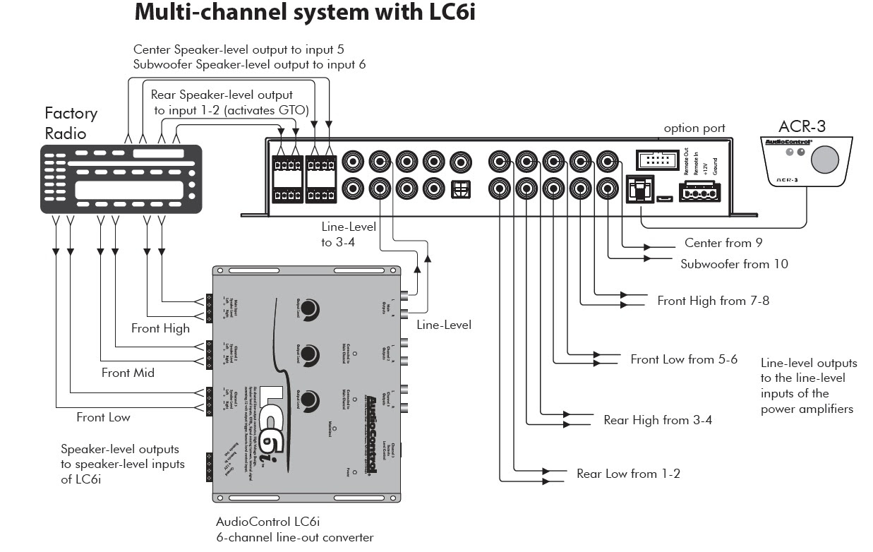
Line Out Converter Wiring Diagram: A visual representation of the connections between a line out converter and an audio system. It outlines the path of audio signals from the source to the amplifier or powered speakers, ensuring proper signal transfer and impedance matching.
Importance, Benefits, and Historical Context: Line out converters play a crucial role in connecting audio sources like CD players or turntables to power amplifiers. They convert high-level, unbalanced line-level signals to low-level, balanced signals that are compatible with most amplifiers. Historically, transformers were used for this purpose, but modern converters employ electronic circuitry for better performance and affordability.
Transition to Main Article Topics: This article will provide a comprehensive guide to line out converter wiring diagrams, covering connection types, wire gauge selection, grounding techniques, and common troubleshooting issues. By understanding these aspects, you can ensure optimal audio performance and enjoy a rich listening experience.
Line Out Converter Wiring Diagrams play a vital role in ensuring proper audio signal transmission and impedance matching in audio systems. Understanding their key aspects is crucial for effective installation and optimal performance.
- Connection Types: Understanding the different types of connections used, such as RCA, XLR, and TRS, ensures compatibility with various audio devices.
- Wire Gauge Selection: Choosing the appropriate wire gauge ensures proper signal transfer and minimizes signal loss.
- Grounding Techniques: Proper grounding techniques eliminate noise and ensure a clean audio signal.
- Signal Level Matching: Line out converters adjust the signal level to match the input requirements of amplifiers.
- Balanced vs. Unbalanced Signals: Understanding the difference between balanced and unbalanced signals helps in selecting the appropriate converter type.
- Impedance Matching: Line out converters ensure proper impedance matching between the source and amplifier, preventing signal reflections and distortion.
- Noise Reduction: Line out converters can incorporate noise reduction features to minimize unwanted noise in the audio signal.
- Troubleshooting Techniques: Identifying common troubleshooting techniques helps resolve issues related to wiring and connections.
- Safety Considerations: Adhering to safety guidelines ensures proper installation and prevents electrical hazards.
These key aspects provide a comprehensive understanding of Line Out Converter Wiring Diagrams. Proper attention to these aspects ensures a well-functioning audio system with optimal sound quality and performance.
Connection Types
In the context of Line Out Converter Wiring Diagrams, understanding the different connection types used is crucial for ensuring seamless compatibility between various audio devices. Different connection types are designed for specific purposes and offer varying levels of signal quality and performance.
- RCA: RCA connectors, commonly known as phono connectors, are widely used in consumer audio applications. They consist of a central pin surrounded by a metal shield and are often used for unbalanced audio signals. RCA connections are commonly found on home audio equipment, such as CD players, turntables, and amplifiers.
- XLR: XLR connectors are professional-grade connectors that are commonly used in balanced audio applications. They feature three pins: one for positive, one for negative, and one for ground. XLR connections are often found on microphones, mixers, and high-end audio equipment. They provide excellent signal quality and are resistant to noise and interference.
- TRS: TRS connectors, also known as phone connectors, are commonly used in semi-professional and professional audio applications. They feature three conductors: tip, ring, and sleeve. TRS connections can be used for both balanced and unbalanced audio signals and are often found on guitars, keyboards, and other musical instruments.
- Other Connection Types: In addition to RCA, XLR, and TRS, there are various other connection types used in audio applications, such as speakON, banana plugs, and DIN connectors. Each type has its own unique characteristics and is suitable for specific applications.
Understanding the different connection types and their appropriate usage is essential for creating a well-functioning audio system. By selecting the right connection type for each component, you can ensure optimal signal transfer, minimize noise and interference, and achieve the best possible sound quality.
Wire Gauge Selection
In “Line Out Converter Wiring Diagrams,” wire gauge selection plays a critical role in ensuring the effective transfer of audio signals and minimizing signal loss. Wire gauge refers to the thickness of the electrical wire, which directly impacts its current-carrying capacity and resistance.
When using a line out converter, choosing the appropriate wire gauge is essential for maintaining signal integrity. Thicker gauge wires have lower resistance, allowing for better signal transfer over longer distances. Conversely, thinner gauge wires have higher resistance, which can lead to signal loss and degradation, especially at higher frequencies.
For example, in a typical audio system, a line out converter may be used to connect a CD player to a power amplifier. If the wire gauge used to connect the converter to the amplifier is too thin, the resistance of the wire can cause a drop in signal level, resulting in reduced volume and compromised sound quality. By using a thicker gauge wire with lower resistance, the signal transfer is more efficient, preserving the original audio quality.
Understanding the relationship between wire gauge selection and signal transfer is crucial for creating a well-functioning audio system. By choosing the appropriate wire gauge based on the length of the cable run and the current requirements of the connected devices, you can ensure optimal signal transfer, minimize signal loss, and achieve the best possible sound quality.
Grounding Techniques
In the context of “Line Out Converter Wiring Diagrams,” grounding techniques play a crucial role in eliminating noise and ensuring a clean audio signal. Grounding refers to the connection of an electrical circuit to a reference point, typically the earth ground, to provide a common potential and prevent unwanted electrical currents from flowing through the system.
- Ground Loop Prevention: Ground loops occur when there are multiple grounding paths between components in an audio system, creating a loop where unwanted currents can flow. Proper grounding techniques involve ensuring that all components share a single common ground point to prevent ground loops and minimize noise.
- Shielding: Shielding involves enclosing cables and components in a conductive material to prevent electrical interference from external sources. Grounding the shield to a common ground point helps drain away any induced currents and minimize noise.
- Star Grounding: In star grounding, all components in an audio system are connected to a central grounding point, like a star-shaped configuration. This ensures that all components share a common ground reference and minimizes the potential for ground loops.
- Isolation Transformers: Isolation transformers can be used to isolate different parts of an audio system, preventing ground loops and noise from entering sensitive components. They provide galvanic isolation by using two separate windings, allowing signals to pass through while blocking unwanted currents.
By implementing proper grounding techniques, you can significantly reduce noise, improve signal-to-noise ratio, and ensure a clean audio signal in your audio system. Understanding and applying these techniques is essential for achieving optimal sound quality and minimizing unwanted interference.
Signal Level Matching
In the context of “Line Out Converter Wiring Diagram,” signal level matching is a crucial aspect that ensures optimal performance of an audio system. Line out converters play a key role in adjusting the signal level from unbalanced line-level sources to match the balanced or unbalanced input requirements of power amplifiers or other audio equipment.
- Output Level Control: Line out converters typically have adjustable output level controls that allow users to match the output signal level to the specific input requirements of their amplifiers. This ensures that the amplifier receives an appropriate signal level, preventing distortion or clipping.
- Input Sensitivity: Amplifiers have varying input sensitivity levels, which determine the minimum signal level required to produce a specified output level. Line out converters help match the output signal level to the input sensitivity of the amplifier, optimizing the signal-to-noise ratio and minimizing distortion.
- Balanced vs. Unbalanced Signals: Line out converters can convert unbalanced line-level signals to balanced signals, which are less susceptible to noise and interference. This conversion ensures that the signal maintains its integrity over longer cable runs and provides a cleaner audio signal to the amplifier.
- Impedance Matching: Line out converters can also provide impedance matching between the source and amplifier. By presenting the proper impedance to the source and amplifier, the converter ensures efficient signal transfer and minimizes reflections that could degrade the audio quality.
Proper signal level matching is essential for achieving optimal audio performance and preventing damage to equipment. By understanding the role of line out converters in adjusting signal level and impedance, one can ensure a well-functioning audio system that delivers clear and distortion-free sound.
Balanced vs. Unbalanced Signals
In the context of “Line Out Converter Wiring Diagram,” understanding the difference between balanced and unbalanced signals is crucial for selecting the appropriate converter type and ensuring optimal audio performance.
Balanced signals use two conductors to carry the audio signal: a positive conductor and a negative conductor. The negative conductor carries an inverted copy of the positive conductor’s signal. At the receiving end, the two signals are combined, and the inverted signal is subtracted from the positive signal, canceling out any noise or interference that may have been picked up along the cable.
Unbalanced signals, on the other hand, use a single conductor to carry the audio signal and a second conductor as a reference ground. This makes them more susceptible to noise and interference, especially over longer cable runs.
In a “Line Out Converter Wiring Diagram,” the type of signal (balanced or unbalanced) that the converter needs to handle is determined by the input requirements of the amplifier or other audio device that the converter is connected to. It is important to match the signal type to the converter to ensure proper signal transfer and minimize noise and interference.
For example, if the amplifier has balanced inputs, a line out converter with balanced outputs should be used. This ensures that the balanced signal is maintained throughout the signal chain, preserving the signal quality and reducing susceptibility to noise.
Understanding the difference between balanced and unbalanced signals and their implications in “Line Out Converter Wiring Diagrams” is essential for selecting the appropriate converter type and achieving optimal audio performance.
Impedance Matching
In the context of “Line Out Converter Wiring Diagram,” impedance matching plays a critical role in ensuring optimal signal transfer and maintaining signal integrity. Line out converters incorporate impedance matching circuitry to prevent signal reflections and distortion, resulting in improved audio quality and performance.
- Source and Load Impedance: Impedance matching involves ensuring that the output impedance of the source (e.g., CD player, turntable) matches the input impedance of the load (e.g., amplifier). Mismatched impedance can lead to signal reflections and power loss.
- Signal Reflections and Distortion: Impedance mismatch can cause signal reflections, where a portion of the signal is reflected back towards the source. These reflections can interfere with the original signal, resulting in distortion and compromised audio quality.
- Line Out Converter as Impedance Buffer: Line out converters act as impedance buffers, presenting a consistent impedance to both the source and the amplifier. This prevents impedance mismatch and ensures efficient signal transfer without reflections or distortion.
- Improved Audio Quality: Proper impedance matching contributes to improved audio quality by minimizing signal loss, reducing distortion, and maintaining the original signal’s integrity throughout the audio chain.
Understanding and implementing proper impedance matching techniques in “Line Out Converter Wiring Diagrams” is crucial for achieving optimal audio performance. By ensuring that the source and amplifier impedances are matched, line out converters help preserve signal quality, enhance sound clarity, and prevent distortion, ultimately delivering a more immersive and enjoyable listening experience.
Noise Reduction
In the context of “Line Out Converter Wiring Diagram,” noise reduction plays a critical role in ensuring a clean and pristine audio signal. Line out converters often incorporate noise reduction circuitry to minimize unwanted noise and interference that can degrade the audio quality.
The connection between noise reduction and line out converter wiring diagrams lies in the fact that proper wiring practices can significantly impact the effectiveness of noise reduction techniques. Factors such as grounding, shielding, and proper cable selection can influence the amount of noise introduced into the audio signal.
Real-life examples of noise reduction within line out converter wiring diagrams include:
- Ground loops: Ground loops can create a path for unwanted currents to flow, resulting in hum or buzzing noise. Proper grounding techniques, such as using a star grounding scheme, can eliminate ground loops and reduce noise.
- Cable shielding: Shielded cables help prevent external noise from interfering with the audio signal. When wiring line out converters, it is important to use shielded cables to minimize noise pickup.
- Proper wire selection: The type and quality of wire used can also affect noise levels. Using high-quality, low-resistance wire can help reduce noise and improve overall audio quality.
Understanding the connection between noise reduction and line out converter wiring diagrams is crucial for achieving optimal audio performance. By implementing proper wiring practices and utilizing noise reduction features in line out converters, audio enthusiasts can effectively minimize unwanted noise and enjoy a clear and immersive listening experience.
Troubleshooting Techniques
In the context of “Line Out Converter Wiring Diagram,” troubleshooting techniques play a vital role in diagnosing and resolving issues related to wiring and connections. Understanding the connection between these two concepts is essential for ensuring a properly functioning audio system.
Troubleshooting techniques provide a systematic approach to identifying and rectifying problems within the wiring and connections of a line out converter. Common issues that may arise include incorrect wiring, loose connections, or faulty components. By employing troubleshooting techniques, audio professionals can efficiently isolate the source of the issue and implement appropriate solutions to restore optimal audio performance.
Real-life examples of troubleshooting techniques within “Line Out Converter Wiring Diagram” include:
- Continuity testing: Using a multimeter to check for continuity between wires and connections helps identify breaks or open circuits.
- Signal tracing: Injecting a test signal into the system and using an oscilloscope to trace the signal path helps locate faulty components or wiring issues.
- Ground loop troubleshooting: Identifying and eliminating ground loops using techniques such as star grounding or ground loop isolators.
Understanding the practical applications of troubleshooting techniques in “Line Out Converter Wiring Diagram” empowers audio professionals to maintain and repair their audio systems effectively. By recognizing the importance of troubleshooting techniques, they can proactively address potential issues, minimize downtime, and ensure the delivery of high-quality audio.
Safety Considerations
In the context of “Line Out Converter Wiring Diagram,” safety considerations play a pivotal role in ensuring a properly installed and hazard-free audio system. Understanding the connection between safety and wiring is paramount to prevent potential electrical issues and maintain optimal performance.
- Proper Grounding: Grounding is essential for safety as it provides a path for electrical currents to flow safely to the earth. Improper grounding can lead to electrical shocks, damage to equipment, and interference in the audio signal.
- Adequate Ventilation: Line out converters, especially those housed in enclosed spaces, require proper ventilation to prevent overheating. Overheating can lead to component failure and potential fire hazards.
- Correct Wiring: Using the correct wire gauge and ensuring proper connections are crucial for safety. Oversized wires can create excessive heat, while loose or faulty connections can lead to arcing and electrical fires.
- Polarity Observance: Observing correct polarity when connecting line out converters is vital. Reversing polarity can not only affect audio quality but also damage connected equipment.
Adhering to these safety guidelines ensures the safe operation of line out converters, protecting both the equipment and the user from potential hazards. Proper installation, adequate ventilation, correct wiring, and polarity observance are essential considerations that contribute to a safe and enjoyable audio experience.


Related Posts


