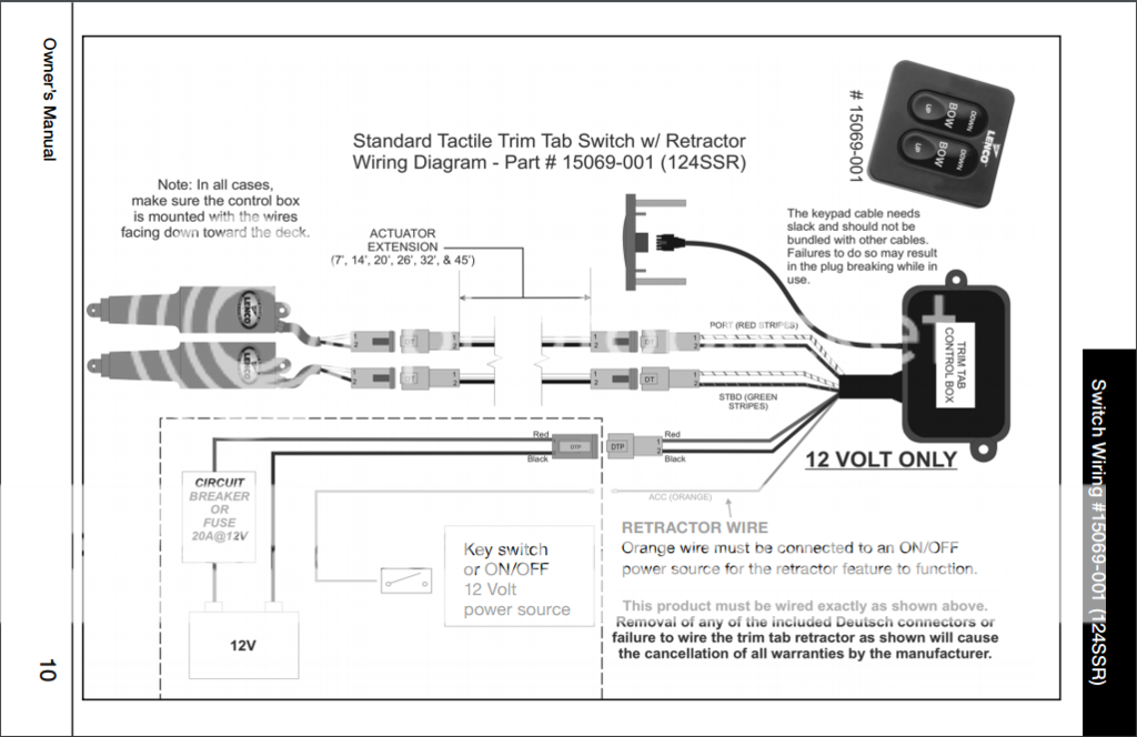
A Lenco Trim Tab Wiring Diagram offers a visual representation of electrical connections within a Lenco trim tab system. It guides the installation and troubleshooting of the system, ensuring proper functionality. For instance, a typical wiring diagram for a Lenco trim tab system outlines the connections between the power source, trim tab switch, actuator, and motor, along with necessary grounding and circuit protection components.
Such a diagram serves as a valuable asset for both professional installers and DIY enthusiasts. It enhances safety, simplifies maintenance, and optimizes the performance of the trim tab system. Its historical significance lies in the automation and precision it brought to trim tab control, allowing for efficient and precise boat handling.
Delving deeper into the nuances of Lenco Trim Tab Wiring Diagrams will provide further insights into their critical components, installation procedures, and troubleshooting techniques, equipping readers with the knowledge to effectively maintain and repair their trim tab systems.
Lenco Trim Tab Wiring Diagrams are essential for guiding the installation, maintenance, and troubleshooting of Lenco trim tab systems. They provide a comprehensive overview of the electrical connections, ensuring optimal performance and safety.
- Components: Power source, switch, actuator, motor, wiring, connectors
- Connections: Detailed layout of electrical pathways between components
- Safety: Grounding and circuit protection measures
- Installation: Step-by-step instructions for proper setup
- Troubleshooting: Identification and resolution of electrical issues
- Automation: Integration with automated control systems
- Optimization: Fine-tuning of trim tab performance
- Customization: Anpassung an spezifische Bootsanforderungen
- Compatibility: Compatibility with different Lenco trim tab models
- Availability: Accessibility of diagrams for various Lenco trim tab systems
These key aspects collectively ensure the proper functioning and longevity of Lenco trim tab systems. By understanding and utilizing these diagrams, boat owners and technicians can maintain optimal boat handling, efficiency, and safety on the water.
Components
Within the realm of Lenco Trim Tab Wiring Diagrams, a thorough understanding of the individual components is paramount for successful installation, maintenance, and troubleshooting. These essential elements work in harmony to ensure the efficient and reliable operation of Lenco trim tab systems.
- Power Source: The electrical energy that drives the trim tab system, typically a 12-volt marine battery.
- Switch: Controls the activation and deactivation of the trim tab system, allowing the operator to adjust the trim angle of the boat.
- Actuator: A linear motor that converts electrical energy into mechanical motion, driving the trim tab up or down.
- Motor: The electrical motor that powers the actuator, providing the necessary torque and speed.
- Wiring: Electrical cables that connect the various components, transmitting power and signals.
- Connectors: Electrical fittings that join the wiring to the components, ensuring secure and reliable connections.
These components form the backbone of Lenco Trim Tab Wiring Diagrams, enabling boat owners and technicians to visualize and understand the electrical connections and pathways within the system. Proper selection, installation, and maintenance of these components are crucial for optimal trim tab performance, ensuring a safe and enjoyable boating experience.
Connections
Within the intricate realm of Lenco Trim Tab Wiring Diagrams, the connections between components play a pivotal role in ensuring the proper functioning and reliability of the entire system. These electrical pathways, meticulously laid out in the diagram, serve as the backbone of the trim tab system, transmitting power and signals to and from each component.
- Power Distribution: The wiring diagram specifies how electrical power flows from the power source to the various components, including the switch, actuator, and motor. Proper wire gauge and connections are crucial for efficient power distribution and minimizing voltage drop.
- Signal Transmission: Control signals from the switch travel through designated wires to activate the actuator and motor. These signals determine the direction and speed of trim tab movement, ensuring precise and responsive control.
- Grounding: Grounding connections provide a safe and stable electrical reference point for the system. Proper grounding prevents electrical faults, protects against interference, and ensures the reliable operation of the trim tab system.
- Circuit Protection: The wiring diagram incorporates circuit protection measures such as fuses or circuit breakers. These devices safeguard the system from electrical overloads and short circuits, preventing damage to components and ensuring the safety of the boat and its occupants.
Understanding the detailed layout of electrical pathways between components in Lenco Trim Tab Wiring Diagrams is essential for proper installation, maintenance, and troubleshooting. By following the diagram meticulously, boat owners and technicians can ensure that all connections are secure, properly sized, and protected, maximizing the performance and longevity of their trim tab systems.
Safety
Within the context of Lenco Trim Tab Wiring Diagrams, safety measures such as grounding and circuit protection play a critical role in ensuring the safe and reliable operation of trim tab systems. Grounding provides a stable electrical reference point, preventing voltage fluctuations and electrical faults that could damage components or pose a safety hazard. Circuit protection devices, such as fuses or circuit breakers, safeguard the system from electrical overloads and short circuits, preventing fires and protecting against electrical damage.
In Lenco Trim Tab Wiring Diagrams, grounding and circuit protection measures are meticulously incorporated to ensure the safety of both the boat and its occupants. The diagram specifies the proper grounding points for the system’s components, ensuring a secure connection to the boat’s electrical ground. Additionally, appropriate fuses or circuit breakers are designated in the diagram, providing the necessary protection against electrical faults and overloads. By following the diagram’s instructions, boat owners and technicians can ensure that their trim tab systems are properly grounded and protected, minimizing the risk of electrical hazards and maximizing the system’s longevity.
Understanding the importance of safety measures in Lenco Trim Tab Wiring Diagrams empowers boat owners and technicians to make informed decisions regarding the installation, maintenance, and troubleshooting of their trim tab systems. By adhering to the specified grounding and circuit protection guidelines, they can proactively prevent electrical issues, ensuring the safety and reliability of their boats.
Installation
In the realm of Lenco Trim Tab Wiring Diagrams, the significance of proper installation cannot be overstated. Installation instructions, meticulously detailed within the diagram, provide a step-by-step guide for technicians and boat owners to ensure the safe and efficient setup of their trim tab systems. These instructions serve as a roadmap, outlining the precise sequence of actions required for successful installation.
The intricate nature of Lenco Trim Tab Wiring Diagrams demands careful adherence to installation procedures. Each step, from mounting the actuator and connecting the wiring to securing the trim tabs and testing the system, is clearly outlined. By following these instructions diligently, boat owners can avoid costly mistakes, ensure optimal performance, and minimize the risk of electrical hazards.
Real-life examples further illustrate the practical applications of installation instructions within Lenco Trim Tab Wiring Diagrams. For instance, precise measurements and alignment during actuator mounting are crucial for accurate trim tab deployment. Proper wiring connections, as specified in the diagram, prevent short circuits and ensure reliable operation. Moreover, thorough testing procedures outlined in the instructions guarantee that the trim tab system functions as intended, providing boat owners with peace of mind.
Understanding the connection between “Installation: Step-by-step instructions for proper setup” and “Lenco Trim Tab Wiring Diagram” empowers boat owners and technicians with the knowledge and confidence to undertake successful trim tab installations. By utilizing these diagrams and adhering to the specified instructions, they can ensure the safety, reliability, and optimal performance of their trim tab systems, enhancing their boating experience.
Troubleshooting
Within the realm of Lenco Trim Tab Wiring Diagrams, troubleshooting plays a pivotal role in maintaining the optimal functionality of trim tab systems. Troubleshooting involves identifying and resolving electrical issues that may arise during installation, operation, or maintenance of the system. A comprehensive wiring diagram serves as an invaluable tool in this process, providing a visual representation of the electrical connections and components.
The troubleshooting section of a Lenco Trim Tab Wiring Diagram typically includes step-by-step instructions for diagnosing and resolving common electrical problems. These instructions guide boat owners and technicians through a series of tests and measurements, helping them isolate the source of the issue and determine the appropriate corrective action. Real-life examples of troubleshooting scenarios are often included, along with detailed diagrams and schematics that illustrate the problem and its solution.
Understanding the connection between troubleshooting and Lenco Trim Tab Wiring Diagrams is crucial for ensuring the reliability and longevity of trim tab systems. By utilizing the troubleshooting instructions provided in the diagram, boat owners and technicians can identify and resolve electrical issues quickly and effectively, minimizing downtime and ensuring a safe and enjoyable boating experience.
Automation
In the realm of Lenco Trim Tab Wiring Diagrams, the integration with automated control systems marks a significant advancement in trim tab technology. It enables the seamless connection of trim tabs to sophisticated control systems, unlocking new possibilities for enhanced boat handling and overall boating experience.
- Centralized Control: Integration with automated control systems allows boaters to centrally manage their trim tabs alongside other boat systems, such as navigation, lighting, and audio, from a single intuitive interface.
- Automatic Adjustment: Automated control systems can monitor boat conditions, such as speed, trim angle, and wave height, and automatically adjust trim tab positions to optimize performance and comfort.
- Enhanced Stability: Integration with autopilot systems enables trim tabs to work in conjunction with the autopilot to maintain a stable and level boat, even in challenging sea conditions.
- Remote Monitoring: Some automated control systems allow remote monitoring of trim tab positions and system status via mobile devices or web interfaces, providing boat owners with peace of mind when away from the helm.
The integration of trim tabs with automated control systems, as depicted in Lenco Trim Tab Wiring Diagrams, revolutionizes the way boaters interact with their trim tabs. It empowers them with greater control, precision, and convenience, ultimately enhancing their boating experience and safety on the water.
Optimization
Within the context of Lenco Trim Tab Wiring Diagrams, optimization plays a crucial role in achieving the desired performance and efficiency from trim tab systems. Optimization involves fine-tuning the trim tab settings to suit the specific characteristics of the boat, its intended use, and environmental conditions.
The Lenco Trim Tab Wiring Diagram provides a comprehensive overview of the electrical connections and components involved in the trim tab system. It serves as a foundation for understanding how adjustments to the wiring and component settings can impact trim tab performance. For instance, precise adjustments to the actuator stroke length and limit switches can optimize the range and responsiveness of the trim tabs, ensuring they effectively counteract boat pitch and roll.
Real-life examples further illustrate the practical applications of optimization within Lenco Trim Tab Wiring Diagrams. Performance boat enthusiasts often fine-tune their trim tab settings to achieve maximum speed and handling. By adjusting the trim tab angle and actuator speed, they can minimize drag, improve acceleration, and enhance cornering capabilities. Additionally, anglers and boaters operating in rough seas may adjust their trim tabs to improve stability, reduce bow rise, and maintain a level running attitude.
Understanding the connection between optimization and Lenco Trim Tab Wiring Diagrams empowers boat owners and technicians to tailor their trim tab systems for optimal performance under diverse operating conditions. It enables them to make informed decisions regarding wiring configurations, component settings, and actuator adjustments, ultimately maximizing the benefits of their trim tab systems.
Customization
Within the realm of Lenco Trim Tab Wiring Diagrams, customization holds significant importance, empowering boat owners and technicians to tailor their trim tab systems to meet the unique requirements of their boats and intended applications. This aspect of customization encompasses various facets, each playing a crucial role in optimizing trim tab performance and enhancing the overall boating experience.
- Actuator Selection: Choosing the appropriate actuator for the boat’s size, weight, and desired trim range ensures optimal performance and longevity.
- Wiring Configuration: Customizing the wiring connections, such as the length and gauge of wires, allows for efficient power distribution and minimizes voltage drop, especially in larger boats.
- Mounting Location: Selecting the optimal mounting location for the trim tabs and actuators ensures proper functionality and protection from underwater obstacles.
- Control Panel Integration: Integrating the trim tab control panel into the boat’s existing electrical system and helm layout provides convenient and ergonomic control.
Understanding the customization capabilities outlined in Lenco Trim Tab Wiring Diagrams empowers boat owners and technicians to create trim tab systems that are tailored to their specific needs. By carefully considering the aforementioned facets and making appropriate adjustments, they can unlock the full potential of their trim tabs, maximizing efficiency, performance, and overall boating satisfaction.
Compatibility
In the realm of Lenco Trim Tab Wiring Diagrams, compatibility with different Lenco trim tab models is a critical consideration that ensures the seamless integration and optimal performance of trim tab systems. Lenco offers a range of trim tab models, each designed for specific boat sizes, types, and performance requirements. Understanding the compatibility between trim tab models and wiring diagrams is essential for boat owners and technicians to make informed decisions and achieve desired outcomes.
Lenco Trim Tab Wiring Diagrams provide detailed instructions and specifications for installing and connecting trim tab systems. These diagrams clearly outline the compatibility of each wiring diagram with specific Lenco trim tab models. By matching the appropriate wiring diagram to the installed trim tab model, boat owners and technicians can ensure that the electrical connections are correct and that the system functions as intended. Incorrect wiring or using an incompatible diagram can lead to electrical faults, poor trim tab performance, or even damage to the system.
Real-life examples further illustrate the importance of compatibility between Lenco trim tab models and wiring diagrams. For instance, the Lenco Type 1 Trim Tab Wiring Diagram is specifically designed for use with Lenco Type 1 trim tabs. This diagram provides precise instructions on wiring the actuator, limit switches, and control panel, ensuring proper functioning of the Type 1 trim tabs. Similarly, the Lenco Type 2 Trim Tab Wiring Diagram is tailored to the electrical requirements of Lenco Type 2 trim tabs, ensuring compatibility and optimal performance.
Understanding the connection between compatibility and Lenco Trim Tab Wiring Diagrams empowers boat owners and technicians to select the appropriate wiring diagram for their specific trim tab model. By carefully matching the wiring diagram to the installed trim tabs, they can ensure a safe, reliable, and efficient trim tab system, enhancing the overall boating experience.
Availability
Within the realm of Lenco Trim Tab Wiring Diagrams, the availability and accessibility of diagrams for various Lenco trim tab systems play a crucial role in ensuring the successful installation, maintenance, and operation of these systems on a wide range of boats.
- Online Resources: The internet provides a wealth of resources, including official manufacturer websites and boating forums, where boat owners and technicians can easily access wiring diagrams for various Lenco trim tab models.
- Printed Manuals: Many Lenco trim tab systems come with detailed printed manuals that include comprehensive wiring diagrams. These manuals are typically included with the system upon purchase and provide a convenient reference for installation and troubleshooting.
- Technical Support: Lenco Marine offers technical support to customers who require assistance with wiring or troubleshooting their trim tab systems. This support includes providing access to wiring diagrams and technical guidance from experienced professionals.
- Third-Party Sources: In addition to official sources, third-party websites and publications often provide access to wiring diagrams for Lenco trim tab systems. These sources can be particularly helpful for older or discontinued models.
The ready availability of wiring diagrams for various Lenco trim tab systems empowers boat owners and technicians with the necessary information to properly install, maintain, and troubleshoot their systems, ensuring optimal performance, safety, and longevity.


Related Posts


