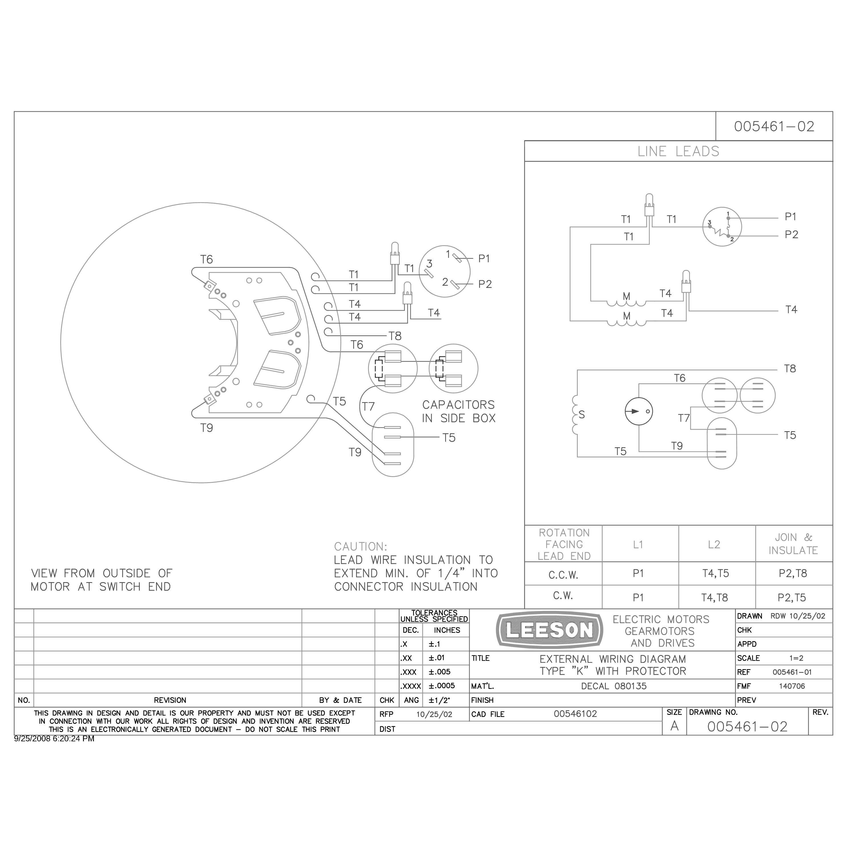
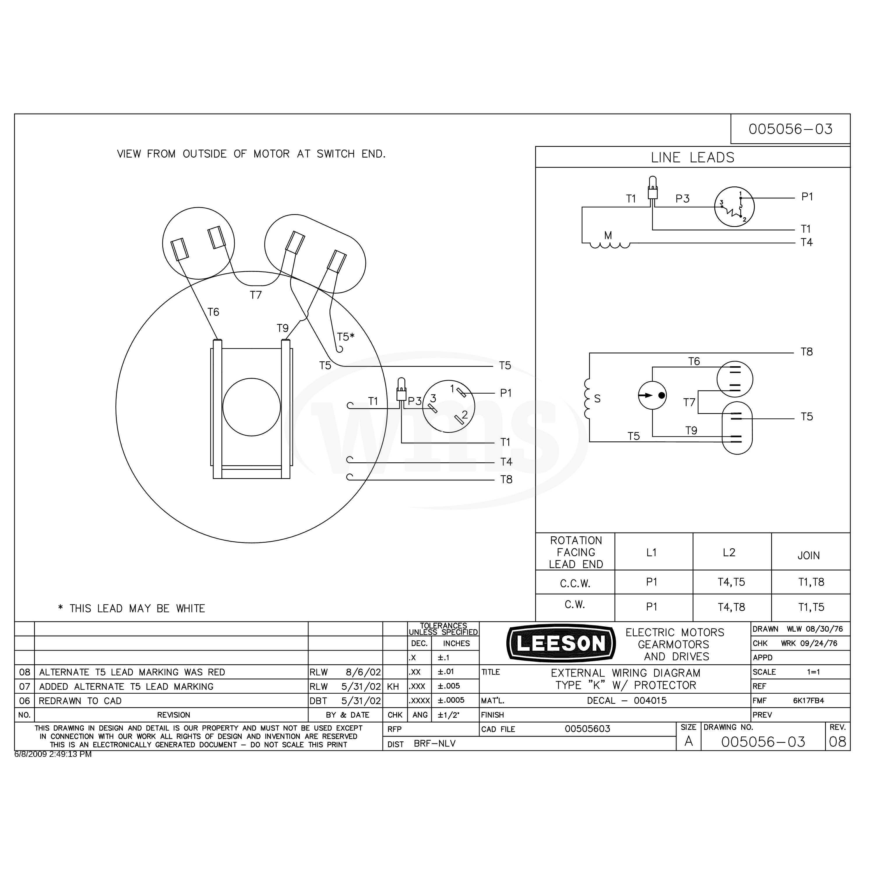
A Leeson Motor Wiring Diagram is a schematic representation of the electrical connections within a Leeson electric motor. It provides a visual guide for electricians and other professionals to properly connect the motor to a power source, ensuring its correct operation and safety. For instance, a Leeson three-phase motor wiring diagram details the connections between its three terminals, a start capacitor, and the power source.
This wiring diagram is highly relevant in industrial and commercial settings, enabling efficient troubleshooting, maintenance, and installation of Leeson motors. It ensures proper motor operation, preventing damage and optimizing system performance. A key historical development in motor wiring was the introduction of standardized color codes for motor leads, simplifying the installation and identification of connections.
This article delves further into the components, configurations, and applications of Leeson Motor Wiring Diagrams, providing detailed explanations and practical examples to facilitate effective motor operation and troubleshooting.
Understanding the essential aspects of a Leeson Motor Wiring Diagram is crucial for ensuring proper installation, operation, and maintenance of Leeson electric motors. These diagrams provide a visual representation of the electrical connections within the motor, enabling efficient troubleshooting and optimization of system performance.
- Components: Terminals, wires, capacitors, resistors
- Configurations: Single-phase, three-phase, AC, DC
- Power Source: Voltage, frequency, current
- Connections: Star, delta, parallel, series
- Color Codes: Standardized colors for motor leads
- Safety: Grounding, insulation, overcurrent protection
- Troubleshooting: Identifying faults, testing procedures
- Maintenance: Inspection, cleaning, lubrication
These aspects are interconnected and play vital roles in the effective operation of Leeson motors. For instance, understanding the correct wire connections and power source requirements ensures that the motor operates at its optimal efficiency and prevents damage. Similarly, knowledge of safety measures, such as proper grounding and overcurrent protection, minimizes electrical hazards and ensures a safe operating environment. By comprehensively considering these aspects, professionals can ensure reliable and efficient operation of Leeson motors in various industrial and commercial applications.
Components
Within a Leeson Motor Wiring Diagram, terminals, wires, capacitors, and resistors play critical roles in establishing and controlling the flow of electricity within the motor. Terminals serve as the connection points for wires, which carry electrical current to and from the motor’s internal components. Capacitors and resistors modify the electrical characteristics of the circuit, influencing factors such as starting torque, speed, and direction of rotation.
The configuration of these components within the wiring diagram directly affects the motor’s performance and functionality. For instance, the type and value of capacitors used can determine the starting torque and speed of the motor, while resistors can regulate current flow and prevent overheating. Proper selection and arrangement of these components are essential to ensure efficient and reliable operation of the motor.
In practical applications, Leeson Motor Wiring Diagrams guide electricians and technicians in correctly connecting and configuring these components. By understanding the relationship between the components and their representation in the wiring diagram, professionals can troubleshoot issues, optimize motor performance, and ensure safety. This understanding is particularly important in industrial settings, where motors are used to power a wide range of equipment and machinery.
In summary, the components of terminals, wires, capacitors, and resistors are fundamental elements of Leeson Motor Wiring Diagrams, dictating the electrical behavior and performance of the motor. Their proper configuration and connection, as outlined in the wiring diagram, are critical for ensuring efficient, safe, and reliable operation in various industrial and commercial applications.
Configurations
Within the context of Leeson Motor Wiring Diagrams, the aspect of “Configurations: Single-phase, three-phase, AC, DC” holds significant importance, as it outlines the various electrical configurations in which Leeson motors can be connected and operated. Understanding these configurations is crucial for selecting the appropriate wiring diagram and ensuring the safe and efficient operation of the motor.
- Power Source: Leeson motors can be configured to operate on either single-phase or three-phase power sources. Single-phase motors are commonly used in residential and light commercial applications, while three-phase motors are more suitable for industrial and heavy-duty applications.
- Current Type: Leeson motors can also be classified based on the type of current they use, either AC (alternating current) or DC (direct current). AC motors are more common and are used in a wide range of applications, while DC motors are used in specific applications, such as battery-powered devices.
- Wiring Diagram: The wiring diagram for a Leeson motor will vary depending on the specific configuration of the motor. Single-phase motors typically have a simpler wiring diagram compared to three-phase motors, which require more complex connections.
- Efficiency: Three-phase motors are generally more efficient than single-phase motors, particularly at higher loads. This is because three-phase motors have a more balanced distribution of magnetic forces, resulting in reduced losses.
By understanding the different configurations available and their implications on the wiring diagram, electricians and technicians can ensure that Leeson motors are properly connected and operated, maximizing efficiency, safety, and performance.
Power Source
Within the context of Leeson Motor Wiring Diagrams, the “Power Source: Voltage, frequency, current” aspect holds critical importance as it directly influences the motor’s operation and performance. Understanding this relationship is essential for selecting the appropriate wiring diagram and ensuring the safe and efficient operation of the motor.
The voltage, frequency, and current of the power source must match the specifications of the Leeson motor to ensure proper operation. Incorrect voltage can lead to motor damage, reduced performance, or complete failure. Similarly, incorrect frequency can cause the motor to run at an improper speed, resulting in reduced efficiency and increased wear and tear. Current is also a critical factor, as overloading the motor can lead to overheating and potential damage.
For example, a Leeson motor designed to operate on a 230-volt, 60-hertz, single-phase power source must be connected to a wiring diagram that provides these specific electrical characteristics. Using a wiring diagram designed for a different voltage, frequency, or phase configuration could result in motor damage or failure.
In practical applications, electricians and technicians must carefully consider the power source specifications when selecting and using Leeson Motor Wiring Diagrams. By matching the wiring diagram to the power source, they can ensure that the motor operates safely, efficiently, and within its intended performance parameters.
Connections
Within the context of Leeson Motor Wiring Diagrams, the aspect of “Connections: Star, delta, parallel, series” plays a critical role in determining how the motor windings are connected to the power source, directly influencing the motor’s performance and characteristics. Understanding these different connection types is essential for selecting the appropriate wiring diagram and ensuring the safe and efficient operation of the motor.
-
Star Connection:
In a star connection, the ends of each motor winding are connected to a common neutral point, forming a “star” shape. This type of connection is commonly used for three-phase motors and provides a more balanced distribution of current, resulting in smoother operation and reduced vibration.
-
Delta Connection:
In a delta connection, the ends of each motor winding are connected in a continuous loop, forming a “triangle” or “delta” shape. This type of connection is also commonly used for three-phase motors and provides a higher starting torque compared to a star connection, but may result in higher current consumption and torque pulsations.
-
Parallel Connection:
In a parallel connection, the motor windings are connected in parallel, allowing the current to be divided between the windings. This type of connection is commonly used for single-phase motors and results in a lower overall impedance, higher current draw, and increased starting torque.
-
Series Connection:
In a series connection, the motor windings are connected in series, with the current flowing through each winding in succession. This type of connection is less commonly used for motors and results in a higher overall impedance, lower current draw, and reduced starting torque.
The choice of connection type depends on factors such as the motor’s power requirements, starting torque needs, and the available power source. By understanding the different connection types and their implications, electricians and technicians can select the appropriate Leeson Motor Wiring Diagram, ensuring optimal motor performance, efficiency, and longevity in various applications.
Color Codes
Within the context of Leeson Motor Wiring Diagrams, the aspect of “Color Codes: Standardized colors for motor leads” plays a critical role in simplifying the identification, connection, and troubleshooting of motor windings. These standardized color codes provide a universal language for electricians and technicians, ensuring consistent and safe practices across various applications.
-
Identification:
Color codes provide a quick and easy method to identify different motor leads, reducing the risk of incorrect connections and potential damage to the motor. Each color is assigned to a specific winding or terminal, allowing for easy tracing and verification during installation and maintenance.
-
Polarity:
In addition to identification, color codes also indicate the polarity of motor leads, distinguishing between positive and negative terminals. This is especially important for DC motors and certain types of AC motors where correct polarity is crucial for proper operation and torque direction.
-
Phasing:
For three-phase motors, color codes help identify the different phases (U, V, W) and their corresponding leads. This ensures correct phasing, which is essential for balanced operation and maximizing motor efficiency.
-
International Standards:
Standardized color codes adhere to international electrical standards, such as IEC 60204-1, ensuring consistency and safety across different countries and regions. This common color coding system facilitates global collaboration and reduces the risk of misinterpretation or errors during motor installation and maintenance.
By utilizing standardized color codes for motor leads, Leeson Motor Wiring Diagrams provide a clear and concise visual guide for electrical professionals, enabling efficient and accurate motor connections. This not only simplifies the installation and maintenance process but also enhances safety and optimizes motor performance in a wide range of industrial and commercial applications.
Safety
Within the context of Leeson Motor Wiring Diagrams, the aspect of “Safety: Grounding, insulation, overcurrent protection” holds critical importance as it outlines the essential measures implemented to protect individuals, equipment, and the motor itself from electrical hazards. These safety features are integral components of a well-designed wiring diagram, ensuring the safe and reliable operation of Leeson motors in various applications.
Grounding, insulation, and overcurrent protection work in conjunction to minimize the risk of electrical shock, short circuits, and motor damage. Grounding provides a low-resistance path for electrical faults to safely dissipate, preventing dangerous voltage buildup on the motor frame or other components. Insulation acts as a barrier between live conductors and other surfaces, preventing accidental contact and short circuits. Overcurrent protection devices, such as fuses or circuit breakers, swiftly interrupt the flow of excessive current, safeguarding the motor from damage caused by overloads or short circuits.
Real-life examples of “Safety: Grounding, insulation, overcurrent protection” within Leeson Motor Wiring Diagrams can be observed in industrial settings, where motors are used to power machinery and equipment. Proper grounding is achieved by connecting the motor frame to an earth ground, providing a safe path for fault currents. Insulation is applied to motor windings and terminals to prevent contact with other components or personnel. Overcurrent protection devices are incorporated into the wiring diagram to protect the motor from damage in the event of excessive current draw.
Understanding the practical significance of “Safety: Grounding, insulation, overcurrent protection” in Leeson Motor Wiring Diagrams enables electrical professionals to design, install, and maintain motors safely and efficiently. By adhering to established safety standards and incorporating these essential features into the wiring diagram, they can mitigate electrical hazards, prevent accidents, and ensure the longevity of Leeson motors in various industrial and commercial applications.
Troubleshooting
Within the context of “Leeson Motor Wiring Diagram”, “Troubleshooting: Identifying faults, testing procedures” plays a crucial role in maintaining the safe and efficient operation of Leeson motors. It involves a systematic approach to diagnose and resolve electrical or mechanical issues that may arise, ensuring optimal performance and longevity of the motor.
-
Fault Identification:
Identifying faults involves analyzing symptoms, such as unusual noises, excessive vibrations, or abnormal temperature rise, to pinpoint potential problems within the motor or its wiring. Through visual inspection, electrical testing, and analysis of operating parameters, the source of the fault can be determined.
-
Testing Procedures:
Testing procedures encompass a range of diagnostic tests, such as insulation resistance tests, continuity checks, and voltage measurements, performed to verify the integrity of motor components and wiring. These tests help identify issues like shorts, grounds, or open circuits, enabling targeted troubleshooting.
-
Component Replacement:
Troubleshooting often involves replacing faulty components, such as bearings, capacitors, or windings, to restore the motor’s functionality. Selecting the correct replacement parts and following proper installation procedures are critical to ensure a successful repair.
-
Comprehensive Analysis:
Beyond specific faults and component failures, troubleshooting involves analyzing the overall electrical and mechanical system in which the motor operates. This includes examining power supply, load conditions, and environmental factors to identify potential contributing factors to motor issues.
By understanding and applying “Troubleshooting: Identifying faults, testing procedures” in conjunction with “Leeson Motor Wiring Diagram”, electrical professionals can effectively diagnose and resolve motor problems, minimize downtime, and ensure reliable operation. It is an essential aspect of maintaining a safe and efficient industrial environment.
Maintenance
As an integral aspect of “Leeson Motor Wiring Diagram”, “Maintenance: Inspection, cleaning, lubrication” plays a crucial role in ensuring the optimal performance, reliability, and longevity of Leeson motors. It encompasses a series of essential tasks that contribute to the proper functioning of the motor over its entire lifespan.
-
Regular Inspections:
Regular inspections involve visually examining the motor and its components for any signs of wear, damage, or contamination. This includes checking for loose connections, frayed wires, and excessive dust or debris accumulation. By identifying potential issues early on, timely corrective actions can be taken to prevent more severe problems.
-
Thorough Cleaning:
Thorough cleaning involves removing dust, dirt, and other contaminants from the motor’s exterior and interior surfaces. This helps maintain proper heat dissipation, prevents the accumulation of conductive particles that could lead to electrical faults, and improves overall motor performance.
-
Proper Lubrication:
Proper lubrication of bearings and other moving parts is essential to reduce friction, minimize wear and tear, and extend the motor’s life. Selecting the correct lubricant type and adhering to recommended lubrication intervals are crucial for ensuring optimal performance and longevity.
-
Environmental Monitoring:
Environmental monitoring involves observing the operating environment of the motor for factors that could affect its performance or lifespan. This includes monitoring temperature, humidity, and exposure to corrosive substances, as these factors can impact motor insulation, bearing life, and overall reliability.
By incorporating “Maintenance: Inspection, cleaning, lubrication” into “Leeson Motor Wiring Diagram”, electrical professionals can develop a comprehensive maintenance plan that ensures the safe, efficient, and long-lasting operation of Leeson motors in various industrial and commercial applications. Neglecting these maintenance aspects can lead to premature motor failure, increased downtime, and compromised system performance.


Related Posts


