Leeson Electric Motor Wiring Diagram is a schematic representation of the electrical connections within a Leeson electric motor. It provides a visual guide for technicians and electricians to understand the motor’s circuitry, troubleshoot issues, and perform maintenance. For instance, when connecting a motor for a specific application, the wiring diagram helps ensure proper wiring to achieve the desired motor performance and direction of rotation.
The diagram is significant as it simplifies the understanding of motor connections and aids in avoiding errors during installation or repair tasks. Benefits include enhanced electrical safety, efficient motor operation, reduced downtime, and prolonged motor lifespan. A key historical development in electric motor wiring diagrams is the standardization of color codes for different wire types, facilitating quick and accurate wire identification.
This article delves into the intricacies of Leeson Electric Motor Wiring Diagrams, covering their essential components, various types, and practical applications in different industries. It will also explore modern advancements and emerging trends in electric motor wiring.
Understanding the essential aspects of Leeson Electric Motor Wiring Diagrams is crucial for proper installation, maintenance, and troubleshooting of electric motors. These diagrams provide a visual representation of the electrical connections within a motor, enabling technicians to comprehend its circuitry and perform tasks efficiently.
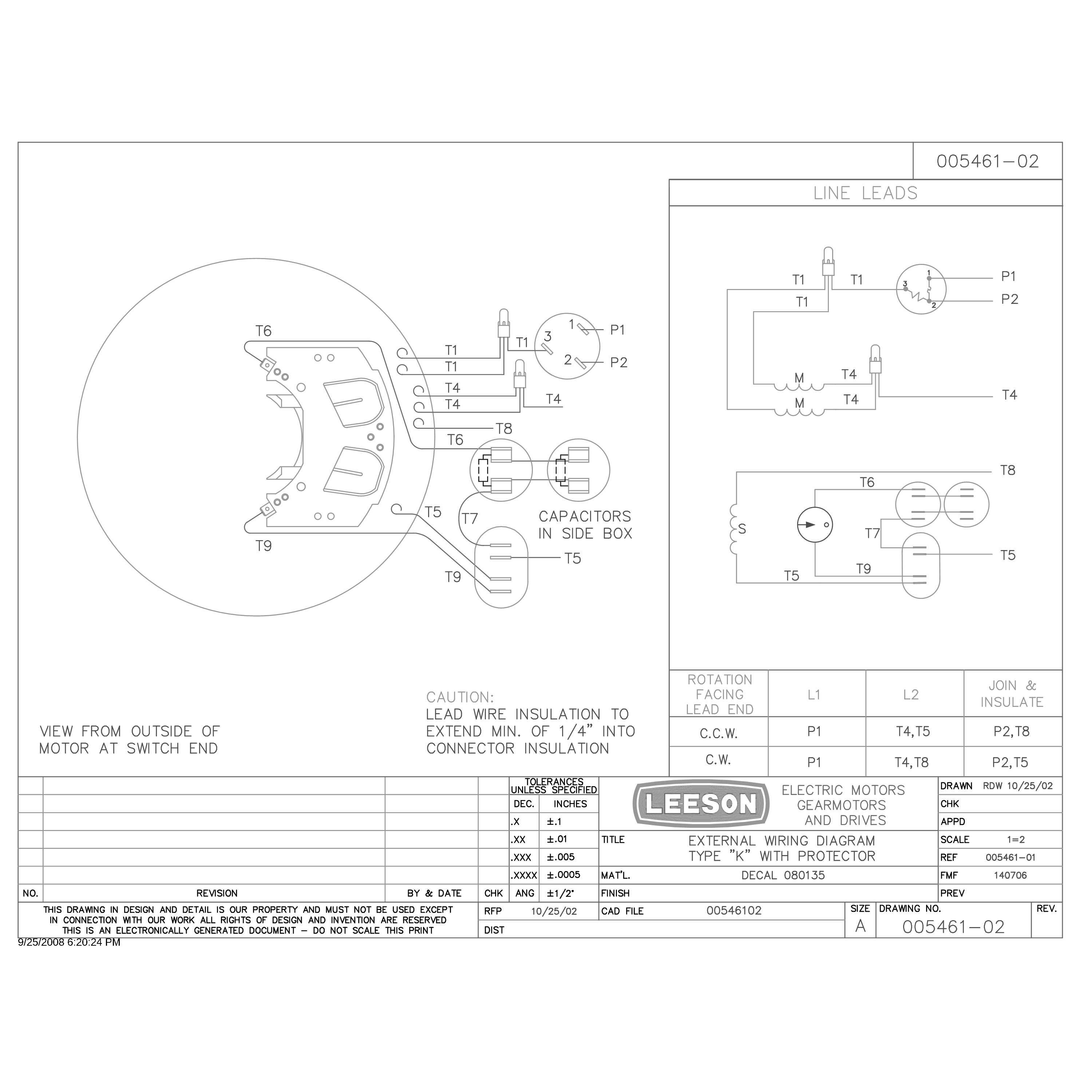
- Components: Wiring diagrams depict the various components of the motor, including terminals, windings, and capacitors, and their interconnections.
- Circuitry: They illustrate the flow of electricity through the motor’s electrical circuits, aiding in understanding its operation.
- Troubleshooting: Diagrams assist in identifying potential electrical faults by providing a clear view of the motor’s connections.
- Maintenance: Proper wiring is essential for motor maintenance, and diagrams guide technicians in performing tasks such as winding replacement.
- Safety: Correct wiring ensures the safe operation of the motor, preventing electrical hazards and accidents.
- Performance: Wiring diagrams contribute to optimizing motor performance by enabling the selection of appropriate connections for specific applications.
- Efficiency: Efficient motor operation is achieved through proper wiring, minimizing energy consumption and extending motor lifespan.
- Standardization: Diagrams follow standardized conventions, facilitating easy interpretation and reducing errors during installation and maintenance.
These aspects collectively highlight the significance of Leeson Electric Motor Wiring Diagrams in ensuring the proper functioning, reliability, and safety of electric motors in various industrial and commercial applications.
Components
Within the context of “Leeson Electric Motor Wiring Diagram”, understanding the individual components and their interconnections is crucial for comprehending the overall functionality and operation of the motor. Wiring diagrams provide a visual representation of these components, enabling technicians to analyze and troubleshoot electrical systems effectively.
- Terminals: These are connection points on the motor where electrical wires are attached. Terminals are typically labeled to indicate their specific function, such as power input, ground, or control signals.
- Windings: Windings are coils of insulated wire wrapped around the motor’s stator or rotor. They create electromagnetic fields when energized, which interact to produce torque and motion.
- Capacitors: Capacitors are electrical components that store energy in an electric field. In motors, capacitors are often used to improve starting torque, enhance power factor, or suppress electrical noise.
- Interconnections: Wiring diagrams illustrate how the terminals, windings, and capacitors are interconnected. These interconnections determine the motor’s electrical configuration, which affects its operating characteristics, such as speed, torque, and efficiency.
By providing a clear depiction of these components and their interconnections, Leeson Electric Motor Wiring Diagrams empower technicians with the knowledge necessary for proper installation, maintenance, and troubleshooting of electric motors. Understanding these components is essential for ensuring the safe and efficient operation of motors in various industrial and commercial applications.
Circuitry
Within the realm of Leeson Electric Motor Wiring Diagrams, understanding the intricate details of motor circuitry is paramount. These diagrams provide invaluable insights into the flow of electricity through a motor’s electrical circuits, offering a comprehensive view of its operation and functionality.
The circuitry depicted in these diagrams serves as a roadmap for technicians, enabling them to trace the path of electrical current as it traverses the motor’s components. By visually representing the interconnections between terminals, windings, and capacitors, wiring diagrams simplify the comprehension of complex electrical systems.
In real-life applications, this understanding is critical for troubleshooting electrical faults. By analyzing the circuitry, technicians can pinpoint the exact location of a problem, minimizing downtime and ensuring efficient motor operation.
Moreover, a thorough grasp of motor circuitry empowers engineers to design and optimize electrical systems for specific applications. They can determine the appropriate wiring configuration to achieve desired performance characteristics, such as speed, torque, and efficiency.
In summary, the circuitry illustrated in Leeson Electric Motor Wiring Diagrams is a fundamental aspect of understanding motor operation and troubleshooting electrical issues. It provides a visual representation of the flow of electricity, enabling technicians and engineers to effectively maintain and optimize electric motors in various industrial and commercial settings.
Troubleshooting
In the realm of Leeson Electric Motor Wiring Diagrams, troubleshooting plays a critical role in ensuring the smooth operation and longevity of electric motors. These diagrams serve as invaluable tools for technicians, providing a clear and comprehensive view of the motor’s electrical connections. By studying the wiring diagram, technicians can quickly identify potential electrical faults and take appropriate corrective actions.
- Fault Identification: Wiring diagrams enable technicians to pinpoint the exact location of an electrical fault within the motor’s circuitry. By tracing the flow of electricity through the diagram, they can identify open circuits, short circuits, or loose connections that may be causing the motor to malfunction.
- Real-Life Examples: In a manufacturing plant, a motor suddenly stops operating. The technician refers to the wiring diagram to identify a blown fuse, which is quickly replaced, restoring the motor to operation with minimal downtime.
- Implications: Accurate troubleshooting using wiring diagrams minimizes repair time, reduces production losses, and enhances overall equipment reliability.
Furthermore, wiring diagrams empower technicians to perform preventive maintenance tasks, such as checking connection tightness and inspecting for signs of wear or damage. By proactively addressing potential issues, they can prevent costly breakdowns and extend the motor’s lifespan. In summary, the troubleshooting aspect of Leeson Electric Motor Wiring Diagrams is essential for maintaining the optimal performance and reliability of electric motors in various industrial and commercial applications.
Maintenance
Within the context of Leeson Electric Motor Wiring Diagrams, maintenance plays a pivotal role in ensuring the longevity and optimal performance of electric motors. Proper wiring is a critical component of effective maintenance, and these diagrams serve as indispensable guides for technicians performing tasks such as winding replacement.
Leeson Electric Motor Wiring Diagrams provide a detailed visual representation of the motor’s electrical connections and circuitry. This enables technicians to thoroughly understand the motor’s electrical system, identify potential issues, and perform maintenance tasks efficiently and accurately. For instance, when a motor requires winding replacement, the wiring diagram guides the technician through the proper steps to remove the old windings and install the new ones, ensuring correct electrical connections and minimizing the risk of errors.
Practical applications of this understanding extend across various industries that rely on electric motors for their operations. In manufacturing, properly maintained motors ensure uninterrupted production processes, reducing downtime and increasing productivity. In commercial settings, such as hospitals or data centers, reliable motor operation is crucial for maintaining critical infrastructure and preventing costly disruptions.
In summary, the connection between “Maintenance: Proper wiring is essential for motor maintenance, and diagrams guide technicians in performing tasks such as winding replacement.” and “Leeson Electric Motor Wiring Diagram” underscores the critical importance of proper wiring for effective motor maintenance. These diagrams empower technicians with the knowledge and guidance necessary to perform maintenance tasks accurately, ensuring the longevity, reliability, and optimal performance of electric motors in diverse industrial and commercial applications.
Safety
Within the context of “Leeson Electric Motor Wiring Diagram”, safety is of paramount importance, as correct wiring practices are crucial for ensuring the safe and reliable operation of electric motors. Wiring diagrams play a vital role in promoting safety by providing a clear and comprehensive representation of the motor’s electrical connections.
Incorrect wiring can lead to electrical hazards and accidents, such as short circuits, overheating, and electrical fires. These can not only damage the motor but also pose a significant safety risk to personnel and the surrounding environment. Leeson Electric Motor Wiring Diagrams help prevent such hazards by guiding technicians in establishing proper electrical connections that comply with safety standards and regulations.
For instance, these diagrams indicate the correct wire sizes and types to be used based on the motor’s current and voltage ratings. By following the diagram, technicians can ensure that the motor is wired to handle the electrical load safely, preventing overheating and potential fires.
Furthermore, wiring diagrams provide instructions on grounding the motor properly. Grounding provides a path for fault currents to flow safely to the earth, minimizing the risk of electrical shock and protecting personnel from injury.
In summary, “Safety: Correct wiring ensures the safe operation of the motor, preventing electrical hazards and accidents.” is a critical component of “Leeson Electric Motor Wiring Diagram” as it emphasizes the importance of proper wiring practices for the safe and reliable operation of electric motors. These diagrams empower technicians with the knowledge and guidance necessary to establish safe electrical connections, preventing potential hazards and ensuring the well-being of personnel and the surrounding environment.
Performance
Within the realm of “Leeson Electric Motor Wiring Diagram”, optimizing motor performance is a critical aspect, as it directly impacts the efficiency, productivity, and lifespan of the motor. Wiring diagrams play a pivotal role in achieving optimal performance by providing a visual representation of the motor’s electrical connections and circuitry.
The connection between “Performance: Wiring diagrams contribute to optimizing motor performance by enabling the selection of appropriate connections for specific applications.” and “Leeson Electric Motor Wiring Diagram” lies in the ability of these diagrams to guide technicians in selecting the correct wiring configuration for a specific application.
For instance, in an industrial setting where a motor is required to operate at a specific speed and torque, the wiring diagram will provide the necessary information on how to connect the motor’s terminals to achieve the desired performance. By selecting the appropriate connections, technicians can ensure that the motor operates within its optimal parameters, maximizing its efficiency and lifespan.
In summary, “Performance: Wiring diagrams contribute to optimizing motor performance by enabling the selection of appropriate connections for specific applications.” is a critical component of “Leeson Electric Motor Wiring Diagram” as it empowers technicians with the knowledge and guidance to configure the motor’s electrical connections for optimal performance in diverse applications. This understanding is essential for maximizing motor efficiency, productivity, and longevity across various industries.
Efficiency
Within the context of “Leeson Electric Motor Wiring Diagram”, optimizing motor efficiency is a critical aspect, as it directly impacts the energy consumption and lifespan of the motor. Wiring diagrams play a pivotal role in achieving optimal efficiency by providing a visual representation of the motor’s electrical connections and circuitry.
The connection between “Efficiency: Efficient motor operation is achieved through proper wiring, minimizing energy consumption and extending motor lifespan.” and “Leeson Electric Motor Wiring Diagram” lies in the ability of these diagrams to guide technicians in establishing the correct electrical connections for a specific application.
For instance, consider an industrial setting where a motor is required to operate continuously for extended periods. Improper wiring can lead to energy losses, overheating, and premature motor failure. Leeson Electric Motor Wiring Diagrams provide detailed instructions on how to connect the motor’s terminals to ensure optimal efficiency. By following the diagram, technicians can select the appropriate wire sizes, types, and connections to minimize energy consumption and extend the motor’s lifespan.
In summary, “Efficiency: Efficient motor operation is achieved through proper wiring, minimizing energy consumption and extending motor lifespan.” is a critical component of “Leeson Electric Motor Wiring Diagram” as it empowers technicians with the knowledge and guidance to configure the motor’s electrical connections for optimal efficiency and longevity. This understanding is essential for maximizing energy savings and reducing maintenance costs across various industries.
Standardization
Within the context of “Leeson Electric Motor Wiring Diagram”, standardization plays a critical role in ensuring consistent interpretation, reducing errors, and enhancing the overall effectiveness of motor installation and maintenance. Leeson Electric Motor Wiring Diagrams adhere to established industry standards and conventions, providing a common language for technicians and engineers working with electric motors.
-
Uniform Symbolism and Color Coding
Standardized symbols and color coding for different components and connections simplify diagram interpretation. This uniformity reduces confusion and minimizes the risk of misinterpretation, especially for technicians working with multiple motor brands or models. -
Logical Layout and Organization
Wiring diagrams follow a logical layout and organization, with clear labeling and annotations. This standardized structure enables technicians to quickly locate specific information and trace electrical connections without ambiguity. -
Compatibility with Industry Standards
Leeson Electric Motor Wiring Diagrams comply with relevant industry standards, such as those established by the National Electrical Manufacturers Association (NEMA) and the Institute of Electrical and Electronics Engineers (IEEE). This ensures compatibility with other electrical components and systems, facilitating seamless integration and reducing the potential for errors. -
Reduced Training Time and Errors
Standardized wiring diagrams minimize the need for extensive training and reduce the likelihood of errors during installation and maintenance. Technicians familiar with the conventions can quickly understand and follow the diagrams, reducing the risk of incorrect connections or misinterpretations.
In summary, the standardization of Leeson Electric Motor Wiring Diagrams contributes to efficient and reliable motor operation by facilitating easy interpretation, minimizing errors, and promoting industry-wide best practices. This standardization enhances safety, reduces downtime, and ensures the optimal performance of electric motors in various industrial and commercial applications.


Related Posts


