A Kawasaki KLR650 Wiring Diagram is a detailed schematic representation of the electrical system of a Kawasaki KLR650 motorcycle. It provides a visual guide to the location, connections, and functions of all electrical components within the motorcycle, including the battery, ignition system, lighting system, and various sensors and actuators.
Wiring diagrams are essential for troubleshooting electrical problems and performing maintenance and repairs on motorcycles. They help technicians and owners identify and locate faulty components, trace electrical circuits, and ensure the proper operation of all electrical systems.
The development of comprehensive wiring diagrams has significantly advanced the field of motorcycle maintenance and repair. Historically, troubleshooting electrical issues was a time-consuming and challenging task, often requiring extensive knowledge and guesswork. With the advent of detailed wiring diagrams, technicians can now quickly and accurately identify the source of electrical problems, resulting in more efficient repairs and reduced downtime.
The Kawasaki KLR650 Wiring Diagram serves as a crucial tool for understanding and maintaining the electrical system of a Kawasaki KLR650 motorcycle. It provides a visual representation of the electrical connections and components, facilitating troubleshooting, repairs, and modifications.
- Accuracy: The wiring diagram accurately reflects the electrical system’s design and layout.
- Comprehensiveness: It includes all electrical components, circuits, and connections within the motorcycle.
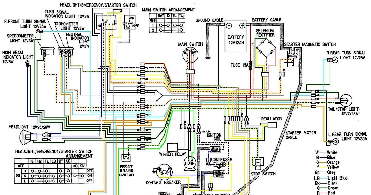
- Clarity: The diagram is easy to read and understand, using standardized symbols and color-coding.
- Troubleshooting: The wiring diagram aids in identifying and isolating electrical faults.
- Repair: It provides a guide for repairing and replacing faulty electrical components.
- Modification: The diagram assists in understanding the electrical system when making modifications or adding accessories.
- Maintenance: It helps in performing regular maintenance tasks, such as checking connections and replacing fuses.
- Safety: The wiring diagram promotes safe electrical practices by providing a clear understanding of the system.
- Historical Documentation: It serves as a valuable historical record of the motorcycle’s electrical system.
These aspects collectively make the Kawasaki KLR650 Wiring Diagram an indispensable resource for motorcycle owners, technicians, and enthusiasts alike. It empowers them to maintain, repair, and modify their motorcycles with confidence and precision.
Accuracy
The accuracy of a Kawasaki KLR650 Wiring Diagram is paramount because it directly affects the reliability, safety, and performance of the motorcycle’s electrical system. An accurate wiring diagram ensures that all electrical components are properly connected and functioning as intended, minimizing the risk of electrical faults, malfunctions, and potential hazards.
For instance, if the wiring diagram inaccurately depicts the connection between the battery and the ignition system, it could lead to incorrect wiring during maintenance or repairs, resulting in a failure to start the motorcycle or even electrical damage. Accurate wiring diagrams prevent such errors by providing a precise representation of the electrical system’s layout and connections.
In practical applications, accurate wiring diagrams are essential for troubleshooting electrical problems. Technicians rely on these diagrams to trace electrical circuits, identify faulty components, and determine the root cause of electrical issues. Without accurate wiring diagrams, troubleshooting becomes a time-consuming and challenging task, often requiring extensive trial and error.
Furthermore, accurate wiring diagrams are crucial for modifications and upgrades to the electrical system. When adding accessories or installing aftermarket components, technicians need to understand the existing electrical system and its connections to ensure compatibility and proper functionality. Accurate wiring diagrams provide this essential information, enabling safe and informed modifications.
In summary, the accuracy of a Kawasaki KLR650 Wiring Diagram is a critical factor in maintaining a reliable, safe, and efficient electrical system. It ensures proper electrical connections, facilitates troubleshooting, and supports modifications, ultimately enhancing the overall performance and longevity of the motorcycle.
Comprehensiveness
The comprehensiveness of a Kawasaki KLR650 Wiring Diagram is essential for its effectiveness and utility. A comprehensive wiring diagram ensures that all electrical components, circuits, and connections within the motorcycle are accurately represented, providing a complete overview of the electrical system.
- Components: The wiring diagram includes all electrical components within the motorcycle, from the battery and starter motor to the ignition system, lighting system, and various sensors and actuators. This comprehensive representation enables technicians and owners to understand the location, function, and interconnections of all electrical components.
- Circuits: The wiring diagram maps out all electrical circuits within the motorcycle, showing how components are connected and how electrical current flows through the system. This information is crucial for troubleshooting electrical problems and understanding the overall functionality of the electrical system.
- Connections: The wiring diagram details all electrical connections within the motorcycle, including wire colors, connector types, and terminal assignments. This information is essential for performing electrical repairs, modifications, and maintenance tasks, ensuring that all connections are made correctly and securely.
- Real-Life Example: A comprehensive wiring diagram is particularly useful when troubleshooting electrical problems. For instance, if a headlight is not functioning, a technician can refer to the wiring diagram to trace the electrical circuit, identify potential points of failure, and isolate the root cause of the problem.
In conclusion, the comprehensiveness of a Kawasaki KLR650 Wiring Diagram is paramount for its effectiveness and utility. It provides a complete overview of the electrical system, including all components, circuits, and connections, enabling technicians and owners to troubleshoot problems, perform repairs, and make modifications with confidence and precision.
Clarity
Clarity is a crucial aspect of a Kawasaki KLR650 Wiring Diagram, as it directly influences the usability and effectiveness of the diagram. A clear and well-organized diagram is essential for quick and accurate troubleshooting, maintenance, and modifications.
- Standardized Symbols: The use of standardized electrical symbols ensures consistency and ease of understanding. These symbols are universally recognized and represent specific electrical components and functions, enabling users to quickly identify and locate components within the diagram.
- Color-Coding: Color-coding is employed to differentiate between different types of circuits and connections. For example, power circuits may be represented using red lines, while ground circuits may be represented using black lines. This color-coding enhances the visual clarity of the diagram, making it easier to trace circuits and identify connections.
- Logical Layout: A clear wiring diagram follows a logical and organized layout, with components and circuits arranged in a manner that reflects their physical location and functionality. This logical layout facilitates the understanding of the overall electrical system and simplifies the process of troubleshooting and maintenance.
- Real-Life Example: A well-designed and clear wiring diagram can significantly reduce the time and effort required for troubleshooting electrical problems. For instance, if a turn signal is malfunctioning, a technician can quickly refer to the wiring diagram to identify the relevant circuit and trace the connections to locate the source of the problem.
In summary, the clarity of a Kawasaki KLR650 Wiring Diagram is paramount for its effectiveness. Standardized symbols, color-coding, and a logical layout work together to enhance readability and comprehension, enabling users to quickly and accurately navigate the electrical system for troubleshooting, maintenance, and modifications.
Troubleshooting
Within the context of a Kawasaki KLR650 Wiring Diagram, troubleshooting is a critical aspect that leverages the diagram’s comprehensive representation of the electrical system. Electrical faults can manifest in various forms, causing disruptions to the motorcycle’s functionality and safety. The wiring diagram serves as an invaluable tool for technicians and owners to identify and isolate these faults.
The cause-and-effect relationship between troubleshooting and the wiring diagram is evident in real-life scenarios. For instance, if a rider experiences a sudden loss of power while riding, they can refer to the wiring diagram to trace the electrical circuit associated with the ignition system. By systematically checking connections, components, and wire continuity, they can identify the source of the fault, whether it’s a loose connection, a faulty component, or a damaged wire.
Practical applications of this understanding extend beyond troubleshooting. The wiring diagram empowers users to proactively maintain their electrical system by identifying potential weak points or areas prone to wear and tear. Regular inspections guided by the diagram can help prevent unexpected electrical failures and ensure the motorcycle’s reliability.
In summary, the troubleshooting capabilities provided by the Kawasaki KLR650 Wiring Diagram are crucial for maintaining a healthy electrical system. By aiding in the identification and isolation of electrical faults, the diagram empowers users to address issues promptly, ensuring the motorcycle’s safe and efficient operation.
Repair
Within the context of a Kawasaki KLR650 Wiring Diagram, the ability to repair and replace faulty electrical components is a critical aspect that directly leverages the information provided by the diagram. Electrical faults, whether minor or major, can disrupt the motorcycle’s performance and safety, requiring prompt attention and resolution.
The Kawasaki KLR650 Wiring Diagram serves as a comprehensive guide for technicians and owners to identify, diagnose, and repair electrical faults effectively. By providing a detailed visual representation of the electrical system, the diagram empowers users to trace circuits, locate components, and understand the interconnections within the motorcycle.
Real-life examples illustrate the practical significance of this connection. For instance, if a rider experiences a sudden loss of lighting while riding at night, they can refer to the wiring diagram to identify the relevant circuit and trace the connections to locate the source of the fault. Armed with this knowledge, they can then proceed to repair or replace the faulty component, restoring the motorcycle’s lighting system to proper functionality.
Another practical application lies in preventive maintenance. By studying the wiring diagram, owners can proactively identify areas prone to wear and tear, loose connections, or potential electrical issues. Regular inspections and maintenance guided by the diagram can help prevent unexpected electrical failures, ensuring the motorcycle’s reliability and safety.
In summary, the Kawasaki KLR650 Wiring Diagram plays a crucial role in enabling repairs and replacements of faulty electrical components. Its comprehensive representation of the electrical system empowers users to troubleshoot, diagnose, and resolve electrical issues efficiently, contributing to the overall reliability and performance of the motorcycle.
Modification
Within the context of a Kawasaki KLR650 Wiring Diagram, modifications and the addition of accessories are common scenarios where the diagram’s value becomes evident. The electrical system of a motorcycle is a complex network of components and circuits, and making changes without a clear understanding can lead to unexpected outcomes or even safety hazards.
The Kawasaki KLR650 Wiring Diagram serves as a roadmap for understanding the electrical system and its interconnections. By providing a visual representation of the system, the diagram empowers users to identify potential connection points, assess the impact of modifications, and plan their electrical work accordingly.
Real-life examples illustrate the practical significance of this connection. For instance, if a rider wants to install additional lighting or heated grips, they can refer to the wiring diagram to identify suitable power sources and determine the appropriate wiring gauge for the added components. This information helps ensure the modifications are integrated seamlessly into the existing electrical system, avoiding potential overloads or compatibility issues.
Another practical application lies in troubleshooting modifications. If an added accessory malfunctions or behaves unexpectedly, the wiring diagram can assist in tracing the circuit and identifying the source of the problem, whether it’s a loose connection, a faulty component, or an incompatibility with the motorcycle’s electrical system.
In summary, the Kawasaki KLR650 Wiring Diagram plays a crucial role in enabling modifications and the addition of accessories. Its comprehensive representation of the electrical system empowers users to plan, implement, and troubleshoot changes to their motorcycle’s electrical system safely and effectively.
Maintenance
Within the context of a Kawasaki KLR650 Wiring Diagram, regular maintenance plays a crucial role in ensuring the motorcycle’s reliability, safety, and optimal performance. The wiring diagram serves as a valuable tool for owners and technicians to perform routine maintenance tasks, including checking electrical connections and replacing fuses.
- Identifying Loose Connections: Electrical connections can become loose over time due to vibrations, temperature changes, or wear and tear. The wiring diagram helps identify all electrical connections within the motorcycle, enabling technicians and owners to visually inspect and tighten loose connections, preventing potential electrical faults.
- Fuse Replacement: Fuses are designed to protect electrical circuits from overcurrent conditions. When a fuse blows, it indicates a potential electrical issue that needs to be addressed. The wiring diagram provides information about the location and type of fuses used in the motorcycle, allowing users to quickly identify and replace blown fuses, restoring electrical functionality.
- Proactive Maintenance: The wiring diagram can be used for proactive maintenance by identifying areas prone to wear and tear or potential electrical issues. By regularly inspecting these areas and addressing any potential problems early on, owners can prevent unexpected electrical failures and ensure the motorcycle’s continued reliability.
- Troubleshooting Support: In conjunction with regular maintenance, the wiring diagram can also assist in troubleshooting electrical problems that may arise. By providing a clear visual representation of the electrical system, the diagram helps technicians and owners trace circuits, identify faulty components, and determine the root cause of electrical issues.
In summary, the “Maintenance: It helps in performing regular maintenance tasks, such as checking connections and replacing fuses.” aspect of a Kawasaki KLR650 Wiring Diagram is essential for maintaining a healthy electrical system and ensuring the motorcycle’s optimal performance. By providing a comprehensive overview of the electrical system, the wiring diagram empowers users to perform regular maintenance tasks, troubleshoot electrical issues, and prevent potential electrical failures, contributing to the motorcycle’s overall reliability and safety.
Safety
The Kawasaki KLR650 Wiring Diagram plays a crucial role in promoting safe electrical practices by providing a clear understanding of the motorcycle’s electrical system. This comprehensive diagram empowers users to identify potential electrical hazards, perform maintenance tasks safely, and troubleshoot electrical issues effectively, contributing to the overall safety and reliability of the motorcycle.
Real-life examples illustrate the practical significance of this connection. For instance, a clear understanding of the electrical system through the wiring diagram enables technicians to identify and potential electrical hazards, such as loose connections or damaged wires, before they can lead to electrical fires or other safety concerns.
Additionally, the wiring diagram provides valuable guidance for maintenance tasks, ensuring that electrical components are serviced and replaced safely. By following the diagram, users can avoid accidental contact with live wires or incorrect connections, reducing the risk of electrical shocks or short circuits.
Furthermore, the wiring diagram is a valuable resource for troubleshooting electrical issues. By providing a clear visual representation of the electrical system, the diagram helps users trace circuits, identify faulty components, and determine the root cause of electrical problems. This understanding enables timely repairs and prevents potential safety hazards caused by unattended electrical issues.
In summary, the safety benefits of the Kawasaki KLR650 Wiring Diagram are undeniable. It promotes safe electrical practices by providing a clear understanding of the electrical system, empowering users to identify hazards, perform maintenance tasks safely, and troubleshoot electrical issues effectively. This contributes to the overall safety and reliability of the motorcycle, ensuring a safer riding experience.
Historical Documentation
Within the context of the Kawasaki KLR650 Wiring Diagram, the aspect of “Historical Documentation” holds significant value in preserving and understanding the motorcycle’s electrical system over time.
- Evolution of Electrical Systems: A wiring diagram captures a snapshot of the electrical system’s design and configuration at a specific point in time. By comparing wiring diagrams across different model years or variants, researchers and enthusiasts can trace the evolution of the electrical system, identifying changes in components, circuits, and overall architecture.
- Diagnostic Aid for Vintage Motorcycles: As motorcycles age, their electrical systems may experience unique challenges and faults. Referring to the original wiring diagram can provide valuable insights into the intended functionality and interconnections of the electrical components, aiding in the accurate diagnosis and repair of vintage motorcycles.
- Preservation of Electrical System Knowledge: Wiring diagrams serve as a repository of knowledge about the motorcycle’s electrical system. As experienced technicians and knowledgeable enthusiasts retire or move on, the wiring diagram ensures that the collective knowledge and understanding of the electrical system is preserved for future generations of owners and mechanics.
In summary, the “Historical Documentation: It serves as a valuable historical record of the motorcycle’s electrical system.” aspect of the Kawasaki KLR650 Wiring Diagram plays a crucial role in preserving the knowledge and understanding of the motorcycle’s electrical system over time. It enables the study of electrical system evolution, assists in the diagnosis and repair of vintage motorcycles, and ensures the continuity of electrical system expertise for future generations.


Related Posts


