A Kawasaki Bayou 300 Wiring Diagram is a schematic representation of the electrical system of the vehicle. It shows the connections between the various electrical components, including the battery, ignition system, lighting system, and more. For instance, the wiring diagram for a 2006 Kawasaki Bayou 300 4×4 ATV can be a valuable resource for troubleshooting electrical problems, making repairs, or customizing the electrical system.
Wiring diagrams are essential for understanding and maintaining the electrical systems of vehicles. They help to identify and locate electrical components, trace circuits, and diagnose problems. One key historical development in the field of wiring diagrams was the introduction of computer-aided design (CAD) software. CAD software allows for the creation of detailed and accurate wiring diagrams that can be easily edited and updated.
This article will provide an overview of the Kawasaki Bayou 300 Wiring Diagram, including its layout, components, and symbols. We will also discuss how to read and interpret a wiring diagram, and how to use it to troubleshoot electrical problems.
The Kawasaki Bayou 300 Wiring Diagram is a crucial resource for understanding and maintaining the electrical system of the vehicle. It provides a comprehensive overview of the electrical components, their connections, and the flow of electricity throughout the system. Understanding the essential aspects of the wiring diagram is key to troubleshooting electrical problems, making repairs, and customizing the electrical system.
- Components: Battery, ignition system, lighting system, gauges, sensors, switches, relays
- Connections: Wires, connectors, terminals, splices, grounds
- Circuits: Power distribution, lighting, ignition, starting, charging
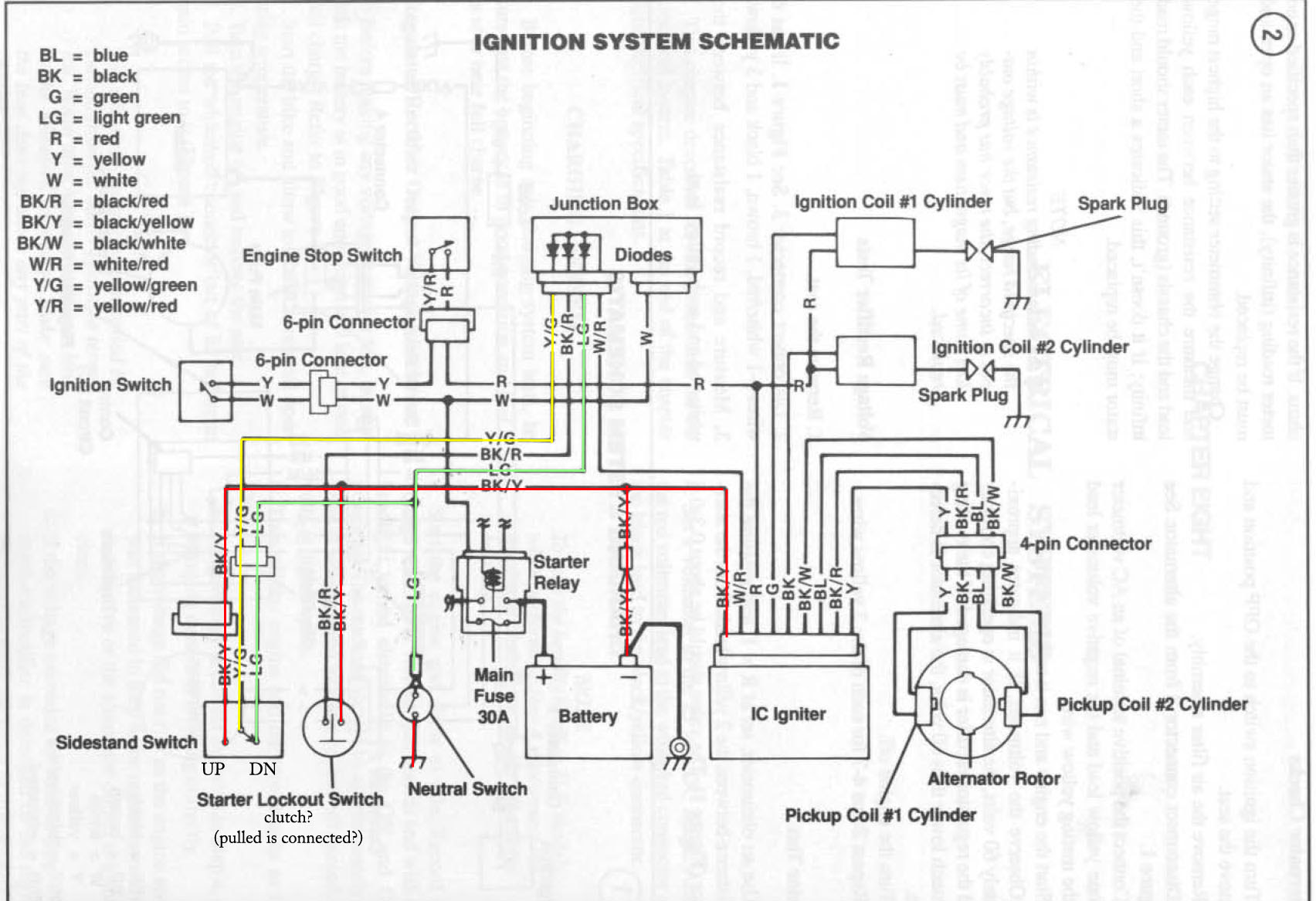
- Symbols: Electrical components are represented by standardized symbols
- Colors: Wire colors are standardized to indicate their function
- Layout: The diagram is organized to show the physical location of components
- Troubleshooting: The diagram can be used to trace circuits and identify faulty components
- Repairs: The diagram provides guidance for making repairs to the electrical system
- Customization: The diagram can be used to plan and implement modifications to the electrical system
These aspects are interconnected and provide a comprehensive understanding of the Kawasaki Bayou 300 Wiring Diagram. For example, the components are connected by wires and connectors, which form circuits that carry electricity throughout the system. The colors of the wires indicate their function, and the symbols on the diagram represent the different electrical components. By understanding these aspects, it is possible to troubleshoot electrical problems, make repairs, and customize the electrical system.
Components
The components of a Kawasaki Bayou 300 Wiring Diagrambattery, ignition system, lighting system, gauges, sensors, switches, and relaysplay critical roles in the proper functioning of the vehicle’s electrical system. These components are interconnected and interdependent, forming a complex network that allows for the distribution and control of electricity throughout the vehicle.
The battery serves as the central power source for the electrical system, providing the necessary voltage to start the engine and power the various electrical components. The ignition system generates the spark that ignites the air-fuel mixture in the engine, while the lighting system provides illumination for night-time riding. Gauges and sensors monitor and display important operating parameters, such as speed, fuel level, and engine temperature.
Switches allow the rider to control the various electrical components, such as lights, horn, and engine kill switch. Relays are electromagnetic switches that are used to control high-power circuits, such as the starter motor and headlights. By understanding the relationship between these components and their representation in the Kawasaki Bayou 300 Wiring Diagram, it is possible to troubleshoot electrical problems, make repairs, and customize the electrical system to meet specific needs.
For example, if the engine fails to start, the wiring diagram can be used to trace the circuit from the battery to the starter motor, checking for any loose connections or faulty components. Similarly, if a headlight fails to illuminate, the wiring diagram can be used to identify the circuit that powers the headlight and to locate any potential problems.
In conclusion, the components of a Kawasaki Bayou 300 Wiring Diagram are essential for the proper functioning of the vehicle’s electrical system. By understanding the relationship between these components and their representation in the wiring diagram, it is possible to diagnose and repair electrical problems, as well as customize the electrical system to meet specific requirements.
Connections
The connections within a Kawasaki Bayou 300 Wiring Diagramwires, connectors, terminals, splices, and groundsare critical components that ensure the proper flow of electricity throughout the vehicle’s electrical system. Without these connections, the various electrical components would be isolated and unable to function.
Wires serve as the pathways for electrical current to travel between different components. Connectors allow for the of wires to each other and to the terminals of electrical components. Terminals provide a secure and reliable point of contact between wires and components. Splices are used to join wires together, creating a continuous electrical path. Grounds provide a low-resistance path for electrical current to flow back to the battery, completing the electrical circuit.
For example, the positive terminal of the battery is connected to one terminal of the starter solenoid through a wire. When the ignition key is turned, the other terminal of the starter solenoid is grounded, completing the circuit and allowing current to flow from the battery to the starter motor, which then cranks the engine.
Understanding the connections within a Kawasaki Bayou 300 Wiring Diagram is essential for troubleshooting electrical problems and making repairs. By tracing the wires and identifying the connectors, terminals, splices, and grounds, it is possible to locate faults and restore the proper flow of electricity.
In conclusion, the connections within a Kawasaki Bayou 300 Wiring Diagram are critical for the proper functioning of the vehicle’s electrical system. By understanding the relationship between these connections and the electrical components they join, it is possible to diagnose and repair electrical problems, ensuring the reliable operation of the vehicle.
Circuits
Within the “Kawasaki Bayou 300 Wiring Diagram,” circuits play a vital role in distributing electrical power and enabling the operation of critical systems. These circuits include power distribution, lighting, ignition, starting, and charging, each serving a specific function to ensure the smooth operation of the vehicle.
- Power Distribution Circuit: Distributes electrical power from the battery to various components such as lights, gauges, and accessories. This ensures that all electrical devices receive the necessary voltage to function properly.
- Lighting Circuit: Provides power to the headlights, taillights, brake lights, and other lighting components. This circuit ensures that the vehicle is visible to other motorists and that the rider can see clearly during nighttime operation.
- Ignition Circuit: Supplies power to the ignition coil, which generates the spark plugs to ignite the air-fuel mixture in the engine. This circuit is crucial for starting and running the engine.
- Starting Circuit: Provides high-amperage power to the starter motor, which engages the engine’s flywheel to start the engine. This circuit ensures that the engine can be started reliably.
- Charging Circuit: Converts alternating current (AC) generated by the stator into direct current (DC), which is then used to charge the battery and power the electrical system. This circuit maintains the battery’s charge and ensures that the electrical system has a constant supply of power.
By understanding the functions and interconnections of these circuits within the “Kawasaki Bayou 300 Wiring Diagram,” technicians and enthusiasts can diagnose and repair electrical problems, customize the electrical system, and ensure the optimal performance of the vehicle.
Symbols
In the context of “Kawasaki Bayou 300 Wiring Diagram,” symbols play a crucial role in representing electrical components in a clear and concise manner. These standardized symbols allow technicians, enthusiasts, and even novice users to understand and interpret the complex electrical system of the vehicle.
- Component Representation: Each electrical component, such as batteries, resistors, switches, and transistors, is represented by a unique symbol. This helps in quickly identifying and locating specific components within the diagram.
- Simplified Depiction: Symbols simplify the representation of complex components, making it easier to understand their function and connections. For instance, a capacitor is represented by two parallel lines, while a diode is depicted as a triangle with a line.
- Universal Understanding: Standardized symbols are universally recognized, allowing anyone familiar with electrical diagrams to interpret the “Kawasaki Bayou 300 Wiring Diagram” regardless of their language or background.
- Schematic Accuracy: Symbols ensure accuracy and consistency in representing electrical circuits. They eliminate the need for detailed drawings or descriptions, making it easier to create and interpret wiring diagrams.
In conclusion, the use of standardized symbols in the “Kawasaki Bayou 300 Wiring Diagram” enhances its clarity, simplifies component representation, promotes universal understanding, and ensures the accuracy of the electrical circuit depiction.
Colors
In the context of the “Kawasaki Bayou 300 Wiring Diagram,” the standardization of wire colors plays a crucial role in simplifying the identification and tracing of electrical circuits. This intentional color-coding system establishes a consistent language that facilitates the understanding and troubleshooting of the vehicle’s electrical system.
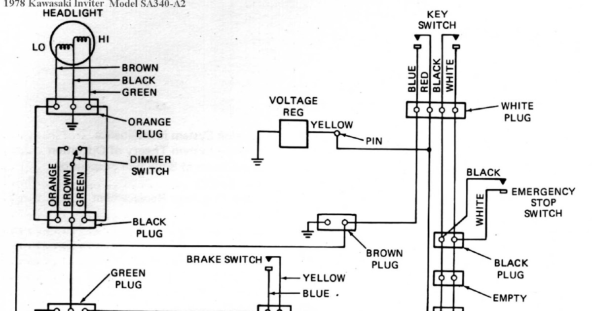
Specific wire colors are assigned to represent different functions or types of circuits, providing a visual cue to technicians and enthusiasts. For instance, in the “Kawasaki Bayou 300 Wiring Diagram,” black wires are typically used for grounding, red wires for power distribution, and yellow wires for lighting circuits. By adhering to these standardized colors, the diagram becomes more intuitive and easier to navigate.
The practical significance of standardized wire colors extends beyond simplifying circuit identification. It also enhances safety by reducing the risk of misconnections and electrical hazards. Consistent color-coding ensures that wires are correctly connected to their intended terminals, preventing potential short circuits or damage to electrical components.
In conclusion, the standardization of wire colors in the “Kawasaki Bayou 300 Wiring Diagram” is a critical component that enhances the clarity, usability, and safety of the electrical system. By assigning specific colors to different functions, the diagram becomes more accessible, allowing for efficient troubleshooting, maintenance, and modifications to the vehicle’s electrical system.
Layout
In the context of the “Kawasaki Bayou 300 Wiring Diagram,” the layout plays a crucial role in conveying the physical arrangement of electrical components within the vehicle. This organized representation allows technicians, enthusiasts, and even novice users to visualize the actual placement of components and their interconnections, which is critical for understanding the electrical system’s functionality and performing maintenance or troubleshooting.
The layout of the diagram is not merely a visual aid but also a functional tool. By depicting the physical location of components, it enables users to trace circuits, identify connections, and locate specific components within the vehicle. This organized arrangement simplifies the process of diagnosing electrical issues, making repairs, and customizing the electrical system. For instance, if a headlight malfunctions, the diagram’s layout allows users to trace the circuit from the headlight switch to the headlight assembly, helping them identify loose connections or faulty components.
The practical significance of the layout extends beyond troubleshooting and repairs. It also aids in the design and modification of the electrical system. By understanding the physical location of components, users can plan and implement upgrades, such as installing additional accessories or modifying the lighting system, without compromising the integrity or safety of the electrical system.
In conclusion, the layout of the “Kawasaki Bayou 300 Wiring Diagram,” which organizes components based on their physical location, is a critical aspect that enhances the diagram’s usability and practical value. It enables users to visualize the electrical system, trace circuits, locate components, and make informed decisions regarding maintenance, repairs, and modifications.
Troubleshooting
In the context of the “Kawasaki Bayou 300 Wiring Diagram,” troubleshooting plays a vital role in diagnosing and resolving electrical issues within the vehicle’s electrical system. The diagram serves as an invaluable tool for tracing circuits and identifying faulty components, enabling users to pinpoint the root cause of electrical malfunctions and perform effective repairs.
The connection between troubleshooting and the “Kawasaki Bayou 300 Wiring Diagram” is bidirectional. The diagram provides a visual representation of the electrical system, allowing users to trace the flow of electricity and identify potential points of failure. Conversely, troubleshooting techniques rely heavily on the diagram to guide the process of identifying faulty components and repairing electrical circuits. Without the diagram, troubleshooting becomes significantly more challenging and time-consuming.
Real-life examples of troubleshooting using the “Kawasaki Bayou 300 Wiring Diagram” include:
- Tracing a circuit to locate a blown fuse or a loose connection that is causing a component to malfunction.
- Using the diagram to identify the correct replacement part for a faulty component, ensuring compatibility and proper functionality.
- Modifying the electrical system by adding accessories or upgrading components, using the diagram as a reference to ensure safe and proper installation.
Understanding the relationship between troubleshooting and the “Kawasaki Bayou 300 Wiring Diagram” is crucial for maintaining and repairing the vehicle’s electrical system. By leveraging the diagram’s visual representation of circuits and components, users can effectively troubleshoot electrical issues, diagnose faults, and implement repairs with confidence.
Repairs
The “Kawasaki Bayou 300 Wiring Diagram” plays a pivotal role in guiding repairs to the vehicle’s electrical system. It provides a comprehensive visual representation of the electrical circuits, components, and their interconnections, serving as an invaluable resource for technicians and enthusiasts alike. Without the diagram, troubleshooting and repairing electrical issues would be significantly more challenging and time-consuming.
The diagram empowers users to trace circuits, identify faulty components, and understand the overall functionality of the electrical system. By referring to the diagram, technicians can pinpoint the exact location of a problem, whether it’s a loose connection, a blown fuse, or a malfunctioning component. This targeted approach minimizes downtime and ensures that repairs are carried out efficiently and accurately.
Real-life examples of repairs guided by the “Kawasaki Bayou 300 Wiring Diagram” include:
- Replacing a faulty starter solenoid by tracing the circuit from the battery to the starter motor, identifying the solenoid as the culprit.
- Repairing a broken wire in the lighting circuit, using the diagram to locate the damaged section and restore the connection.
- Upgrading the headlight bulbs to higher wattage options, referencing the diagram to determine the appropriate wiring and connections.
The practical significance of understanding the relationship between repairs and the “Kawasaki Bayou 300 Wiring Diagram” extends to both professional technicians and DIY enthusiasts. By leveraging the diagram’s comprehensive information, they can diagnose and resolve electrical issues with confidence, ensuring the optimal performance and reliability of the vehicle’s electrical system.
Customization
The “Kawasaki Bayou 300 Wiring Diagram” is a powerful tool not only for troubleshooting and repairs but also for customizing and modifying the vehicle’s electrical system. By understanding the layout, connections, and components depicted in the diagram, users can plan and implement modifications to suit their specific needs and preferences.
-
Electrical Accessory Integration
The diagram provides insights into the electrical system’s capacity and compatibility, enabling users to integrate additional accessories such as lighting, audio systems, or performance enhancements.
-
Performance Upgrades
By studying the diagram, users can identify opportunities to upgrade components, such as replacing the stock ignition coil with a high-performance coil to improve spark intensity and engine performance.
-
Custom Lighting Modifications
The diagram guides users in modifying the lighting system, allowing them to enhance visibility, add custom lighting effects, or install aftermarket lighting components.
-
Electrical System Optimization
The diagram empowers users to optimize the electrical system’s efficiency and reliability by identifying areas for improvement, such as upgrading wiring harnesses or installing additional grounding points.
These customization possibilities extend the functionality and versatility of the Kawasaki Bayou 300, empowering users to tailor the electrical system to their unique requirements and preferences. Whether it’s enhancing performance, improving safety, or simply adding personal touches, the “Kawasaki Bayou 300 Wiring Diagram” serves as an indispensable guide for electrical system customization.


Related Posts


