A John Deere STX38 Wiring Diagram is an extensive illustration that depicts the electrical system and circuitry of a John Deere STX38 lawn tractor. It outlines the connections between the various electrical components, such as the battery, starter, ignition switch, and headlights, providing a visual representation of the tractor’s electrical network.
The diagram serves as a crucial tool for troubleshooting electrical issues, facilitating the identification of faulty connections or damaged components. Its comprehensive detail enables technicians and DIY enthusiasts to trace the flow of electricity throughout the tractor, enabling them to pinpoint the source of electrical problems efficiently and accurately. Additionally, it aids in the installation of new electrical accessories or replacement of existing ones.
The advancement of computerized drafting and design software has significantly enhanced the accuracy and accessibility of wiring diagrams. The transition to digital diagrams has facilitated easy viewing, printing, and sharing, streamlining the process of troubleshooting and maintenance.
For the topic “John Deere STX38 Wiring Diagram,” understanding the essential aspects is crucial as they provide a comprehensive view of the diagram’s purpose, components, and significance. These aspects encompass:
- Schematic Representation: The diagram visually depicts the electrical system and its components.
- Troubleshooting Tool: It aids in identifying and resolving electrical issues.
- Electrical System Overview: It provides a bird’s-eye view of the tractor’s electrical network.
- Connector Identification: It helps locate and identify electrical connectors and terminals.
- Maintenance Planning: The diagram assists in planning and executing electrical maintenance tasks.
- Custom Accessory Integration: It facilitates the installation of additional electrical accessories.
- DIY Repairs: The diagram empowers individuals to troubleshoot and repair electrical problems independently.
- Safety Enhancements: It promotes electrical safety by providing a clear understanding of the system’s layout.
- Improved Efficiency: The diagram enhances the efficiency of electrical troubleshooting and repair processes.
These aspects collectively contribute to the value and functionality of the John Deere STX38 Wiring Diagram, making it an indispensable resource for maintaining and troubleshooting the electrical system of the tractor. By comprehending these aspects, users can leverage the diagram’s capabilities effectively, ensuring the optimal performance and longevity of their equipment.
Schematic Representation
In the context of the John Deere STX38 Wiring Diagram, schematic representation plays a pivotal role in conveying the intricate details of the tractor’s electrical system. It serves as a visual guide, allowing users to comprehend the interconnections between various electrical components and their respective functions within the overall electrical network.
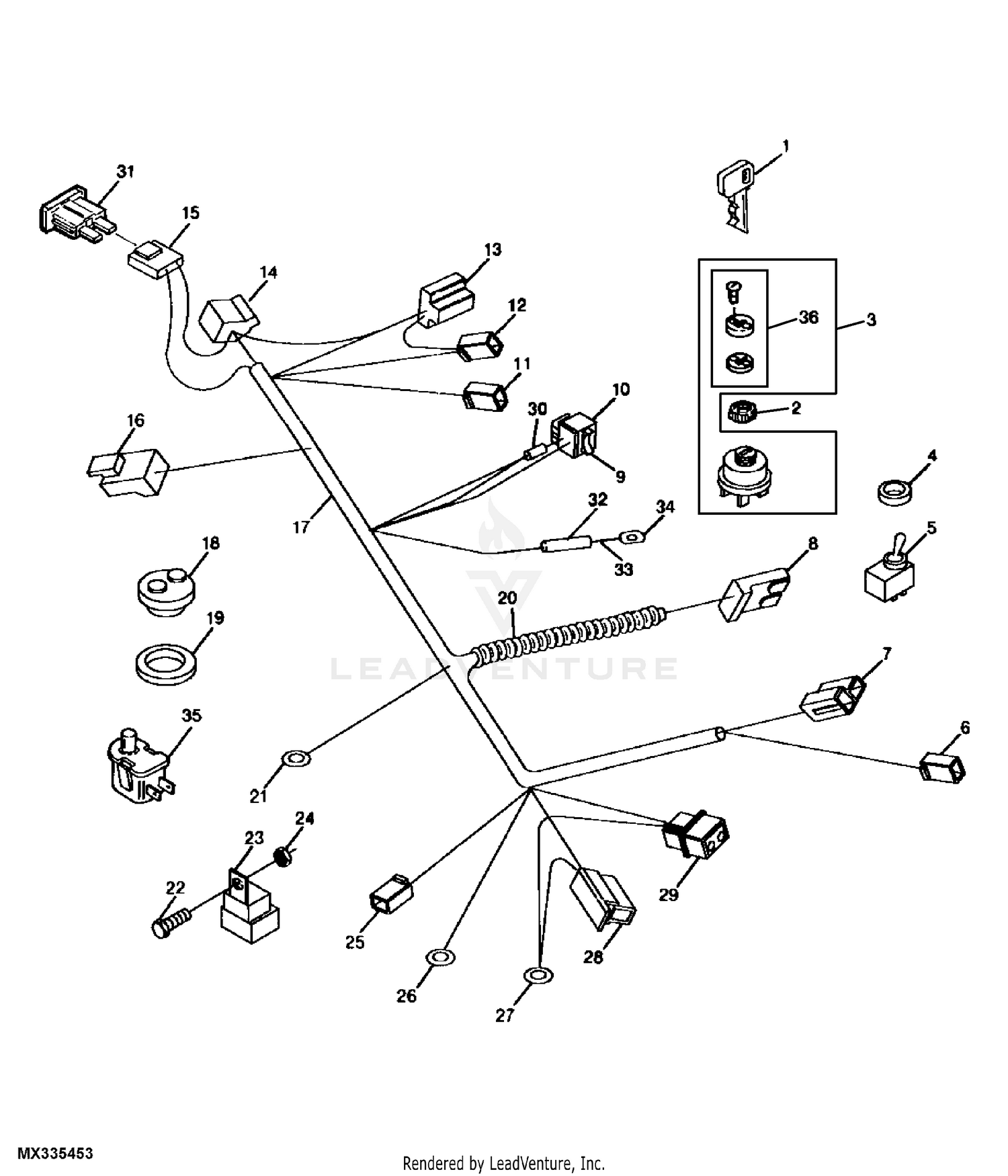
- Component Identification: The diagram clearly labels and identifies each electrical component, such as the battery, starter, ignition switch, and headlights, enabling easy recognition and understanding of their roles in the electrical system.
- Circuit Visualization: It graphically represents the flow of electricity through the electrical circuits, allowing users to trace the path of current from the power source to the various components and back to the ground.
- Connector Mapping: The diagram provides a detailed map of electrical connectors and terminals, indicating their locations and the specific wires that connect to them, facilitating efficient troubleshooting and maintenance.
- System Overview: The schematic representation offers a comprehensive view of the entire electrical system, enabling users to grasp the interrelationships between different components and circuits, promoting a thorough understanding of the system’s operation.
These facets of schematic representation collectively contribute to the effectiveness of the John Deere STX38 Wiring Diagram as a troubleshooting and maintenance tool. By visually depicting the electrical system and its components, the diagram empowers users to diagnose and resolve electrical issues efficiently and accurately, ensuring the optimal performance and longevity of their equipment.
Troubleshooting Tool
Within the context of the John Deere STX38 Wiring Diagram, the aspect of “Troubleshooting Tool: It aids in identifying and resolving electrical issues” holds significant importance. The diagram serves as a comprehensive resource for diagnosing and rectifying electrical problems, empowering users to maintain the optimal performance of their equipment.
- Circuit Analysis: The diagram enables users to trace electrical circuits and identify potential points of failure, such as loose connections, damaged wires, or faulty components, facilitating efficient troubleshooting.
- Component Testing: By referring to the diagram, users can pinpoint specific components for testing, such as switches, sensors, or relays, using multimeters or other diagnostic tools to determine their functionality and identify any issues.
- Real-Life Examples: Suppose a user encounters a situation where the tractor’s headlights are not functioning. By consulting the wiring diagram, they can trace the circuit associated with the headlights, identify potential causes such as blown fuses, loose connections, or faulty switches, and proceed with targeted troubleshooting.
- Implications: The troubleshooting capabilities provided by the wiring diagram empower users to resolve electrical issues independently, saving time and resources compared to relying solely on professional repair services.
In summary, the “Troubleshooting Tool: It aids in identifying and resolving electrical issues” aspect of the John Deere STX38 Wiring Diagram is a valuable asset for maintaining and repairing the electrical system of the tractor. By providing a visual representation of the electrical circuits and components, the diagram allows users to diagnose and resolve electrical problems efficiently and accurately, ensuring the optimal performance and longevity of their equipment.
Electrical System Overview
Delving into the aspect of “Electrical System Overview: It provides a bird’s-eye view of the tractor’s electrical network” within the context of the “John Deere STX38 Wiring Diagram” unveils its significance in understanding and maintaining the electrical system of the tractor. This overview serves as a comprehensive visual representation, enabling users to grasp the overall structure and interconnections of the electrical components.
- Component Identification and Location: The diagram provides a clear layout of the electrical components, including their physical locations within the tractor. This allows users to quickly identify and locate specific components, such as fuses, relays, and sensors, facilitating efficient troubleshooting and maintenance.
- Circuit Visualization: The diagram depicts the electrical circuits in a logical and organized manner, enabling users to trace the flow of electricity throughout the system. This visual representation simplifies the understanding of complex circuits and their interdependencies.
- Power Distribution: The diagram illustrates the distribution of electrical power from the battery to various components and circuits. This overview helps users comprehend how power is supplied and utilized within the electrical system, aiding in the identification of potential power distribution issues.
- Grounding System: The diagram also includes the grounding system, which plays a crucial role in ensuring the proper functioning of the electrical system. Users can understand the grounding points and their connections, enabling them to troubleshoot grounding-related problems effectively.
In summary, the “Electrical System Overview: It provides a bird’s-eye view of the tractor’s electrical network” aspect of the John Deere STX38 Wiring Diagram empowers users with a comprehensive understanding of the electrical system’s layout, components, circuits, power distribution, and grounding. This overview serves as a valuable resource for troubleshooting, maintenance, and gaining a thorough knowledge of the tractor’s electrical system.
Connector Identification
Within the context of “John Deere Stx38 Wiring Diagram”, “Connector Identification: It helps locate and identify electrical connectors and terminals.” plays a pivotal role in understanding and maintaining the intricate electrical system of the tractor. Accurate identification of connectors and terminals is essential for effective troubleshooting, maintenance, and repair of electrical components.
- Connector Types: The diagram provides clear identification of different types of electrical connectors used in the tractor’s electrical system. This includes , terminals, and other connection points, each with its unique design and function.
- Location Mapping: The diagram serves as a comprehensive map, indicating the precise locations of electrical connectors and terminals throughout the tractor. This allows users to quickly locate specific connectors, facilitating efficient troubleshooting and maintenance procedures.
- Color Coding and Labeling: Many wiring diagrams employ color coding and labeling to differentiate between various connectors and terminals. This visual cue simplifies the identification process, especially when dealing with complex electrical systems.
- Real-Life Example: Suppose a user encounters an issue with the tractor’s lighting system. By referring to the wiring diagram, they can identify the specific connector associated with the lighting circuit. This information enables them to locate the connector, inspect it for loose connections or damage, and perform necessary repairs or replacements.
In summary, “Connector Identification: It helps locate and identify electrical connectors and terminals.” is a crucial aspect of the “John Deere Stx38 Wiring Diagram”. It provides users with a clear understanding of the location, types, and functions of electrical connectors and terminals within the tractor’s electrical system. This information is invaluable for troubleshooting, maintenance, and repair tasks, ensuring the optimal performance and longevity of the tractor.
Maintenance Planning
Within the context of the “John Deere STX38 Wiring Diagram,” the aspect of “Maintenance Planning: The diagram assists in planning and executing electrical maintenance tasks” holds significant relevance in ensuring the optimal performance and longevity of the tractor’s electrical system. The diagram serves as a valuable tool for planning and executing electrical maintenance tasks, enabling users to proactively maintain and troubleshoot the electrical system.
- Identifying Maintenance Points: The wiring diagram provides a comprehensive overview of the electrical system, allowing users to identify potential maintenance points, such as connectors, terminals, and components that require regular inspection and servicing.
- Maintenance Scheduling: By referring to the diagram, users can develop a structured maintenance schedule, ensuring that electrical components are inspected, cleaned, and tested at appropriate intervals, reducing the likelihood of unexpected failures.
- Troubleshooting Support: The diagram aids in troubleshooting electrical issues by providing a visual representation of the system’s components and circuits. This enables users to pinpoint potential problem areas and plan targeted maintenance tasks to resolve issues efficiently.
- Real-Life Example: Suppose a user notices intermittent issues with the tractor’s lighting system. Consulting the wiring diagram, they can identify the electrical components associated with the lighting circuit and schedule a maintenance task to inspect and test these components, ensuring reliable lighting performance.
In summary, “Maintenance Planning: The diagram assists in planning and executing electrical maintenance tasks” is a crucial aspect of the “John Deere STX38 Wiring Diagram.” It empowers users to proactively maintain the tractor’s electrical system, prevent potential problems, and ensure the optimal functioning of electrical components, contributing to the longevity and reliability of the equipment.
Custom Accessory Integration
Within the comprehensive framework of the “John Deere STX38 Wiring Diagram,” the aspect of “Custom Accessory Integration: It facilitates the installation of additional electrical accessories” holds significant importance. This aspect empowers users to enhance the functionality and versatility of their tractor by seamlessly integrating additional electrical accessories.
- Accessory Identification: The wiring diagram provides a comprehensive overview of the electrical system, enabling users to identify suitable connection points and determine the compatibility of potential accessories with the tractor’s electrical system.
- Circuit Planning: Before installing any additional accessories, the wiring diagram allows users to plan the electrical circuit, ensuring proper power distribution and avoiding overloading or damage to the system.
- Real-Life Example: Suppose a user desires to install a light bar for improved visibility during nighttime operations. By referring to the wiring diagram, they can identify the appropriate power source, determine the required wire gauge, and plan the routing of the electrical wires to the light bar.
- Safety Considerations: The wiring diagram also highlights safety considerations, such as proper grounding and fuse protection, ensuring that additional accessories are integrated safely and in compliance with electrical standards.
In summary, the “Custom Accessory Integration: It facilitates the installation of additional electrical accessories” aspect of the “John Deere STX38 Wiring Diagram” empowers users to expand the capabilities of their tractor by seamlessly integrating custom electrical accessories. The diagram serves as a valuable resource for planning, installing, and maintaining these accessories, ensuring optimal performance and safety.
DIY Repairs
Within the context of the “John Deere STX38 Wiring Diagram,” the aspect of “DIY Repairs: The diagram empowers individuals to troubleshoot and repair electrical problems independently” holds significant importance, as it enables users to maintain and repair their tractor’s electrical system without relying solely on professional assistance.
The wiring diagram provides a comprehensive visual representation of the electrical system, allowing users to understand the connections between various components, trace circuits, and identify potential issues. This empowers them to diagnose and resolve electrical problems independently, saving time and resources.
For example, if a user encounters an issue with the tractor’s starting system, they can refer to the wiring diagram to identify the components involved in the starting circuit, such as the battery, starter solenoid, and ignition switch. By tracing the circuit and testing individual components, they can pinpoint the source of the problem and perform the necessary repairs.
The ability to perform DIY repairs using the wiring diagram not only enhances the user’s knowledge of their tractor’s electrical system but also fosters a sense of self-reliance and accomplishment. It empowers them to maintain their equipment in optimal condition, ensuring its longevity and reliability.
In summary, the “DIY Repairs: The diagram empowers individuals to troubleshoot and repair electrical problems independently” aspect of the “John Deere STX38 Wiring Diagram” is a valuable resource for users who seek to maintain and repair their tractor’s electrical system independently. It provides a comprehensive visual representation of the system, enabling users to diagnose and resolve electrical issues efficiently, ultimately contributing to the longevity and reliability of their equipment.
Safety Enhancements
The “John Deere STX38 Wiring Diagram” places a high priority on electrical safety by offering a comprehensive visual representation of the tractor’s electrical system. This clear depiction enables users to grasp the system’s layout and make informed decisions when working with electrical components, thereby minimizing the risk of electrical hazards.
A thorough understanding of the wiring diagram empowers users to identify potential electrical hazards, such as improper connections, overloaded circuits, and faulty components. By recognizing these hazards, users can take proactive measures to mitigate risks, such as ensuring proper insulation, using appropriate fuse ratings, and avoiding modifications that could compromise the system’s integrity.
For instance, the wiring diagram clearly illustrates the grounding system, which plays a crucial role in preventing electrical shocks. By understanding the grounding points and their connections, users can ensure that the electrical system is adequately grounded, minimizing the risk of electrical accidents.
Furthermore, the wiring diagram serves as a valuable reference for troubleshooting electrical issues. By tracing circuits and identifying components, users can efficiently diagnose and resolve problems, reducing the likelihood of electrical fires or other safety concerns.
In summary, the “Safety Enhancements: It promotes electrical safety by providing a clear understanding of the system’s layout” aspect of the “John Deere STX38 Wiring Diagram” is a critical component that empowers users to work safely with the tractor’s electrical system. By providing a comprehensive visual representation, the diagram fosters electrical safety awareness, enables proactive hazard mitigation, and facilitates efficient troubleshooting, ultimately contributing to the safe operation and maintenance of the tractor.
Improved Efficiency
Within the context of the “John Deere Stx38 Wiring Diagram,” the aspect of “Improved Efficiency: The diagram enhances the efficiency of electrical troubleshooting and repair processes” takes center stage, offering significant advantages that streamline electrical maintenance and repairs.
The wiring diagram serves as a comprehensive and visually intuitive guide, enabling users to quickly trace electrical circuits, identify components, and locate potential issues. This visual representation simplifies the troubleshooting process, reducing the time and effort required to diagnose electrical problems.
For example, suppose a user encounters a malfunctioning electrical component, such as a faulty light or sensor. By referring to the wiring diagram, they can swiftly identify the circuit associated with the component and trace it to pinpoint the exact location of the issue. This targeted approach minimizes the need for extensive testing and guesswork, leading to faster repairs and reduced downtime.
Furthermore, the wiring diagram empowers users to plan and execute repairs efficiently. By understanding the connections and relationships between electrical components, they can determine the necessary steps and materials required for the repair, ensuring that the process is completed correctly and without unnecessary delays.
In summary, the “Improved Efficiency: The diagram enhances the efficiency of electrical troubleshooting and repair processes” aspect of the “John Deere Stx38 Wiring Diagram” is a critical component that significantly enhances the maintenance and repair experience. The diagram’s visual representation simplifies troubleshooting, reduces downtime, and enables users to execute repairs with greater efficiency and accuracy.


Related Posts


