A John Deere PTO switch wiring diagram provides the detailed electrical connections and pathways for the power take-off (PTO) switch in John Deere equipment. The PTO switch is crucial for engaging and disengaging the PTO, which transfers power from the engine to external implements, such as mowers or tillers.
Wiring diagrams are essential for troubleshooting electrical issues, maintaining proper operation, and ensuring the safe use of PTO-powered equipment. Understanding the wiring diagram enables technicians and operators to diagnose and repair any malfunctions or damage, preventing costly downtime and ensuring optimal performance.
Historically, John Deere has played a significant role in the development of agricultural machinery and technology. Their contributions to PTO systems and wiring diagrams have helped advance the efficiency, safety, and reliability of modern farming equipment. This article will explore the specific wiring diagram of a John Deere PTO switch, providing a comprehensive understanding of its components, connections, and troubleshooting procedures.
The John Deere PTO switch wiring diagram plays a vital role in the operation and maintenance of John Deere equipment. Understanding its key aspects is crucial for ensuring proper function, troubleshooting electrical issues, and maximizing the efficiency of PTO-powered implements.
- Purpose: The wiring diagram provides a detailed roadmap of the electrical connections and pathways for the PTO switch, enabling the transfer of power from the engine to external implements.
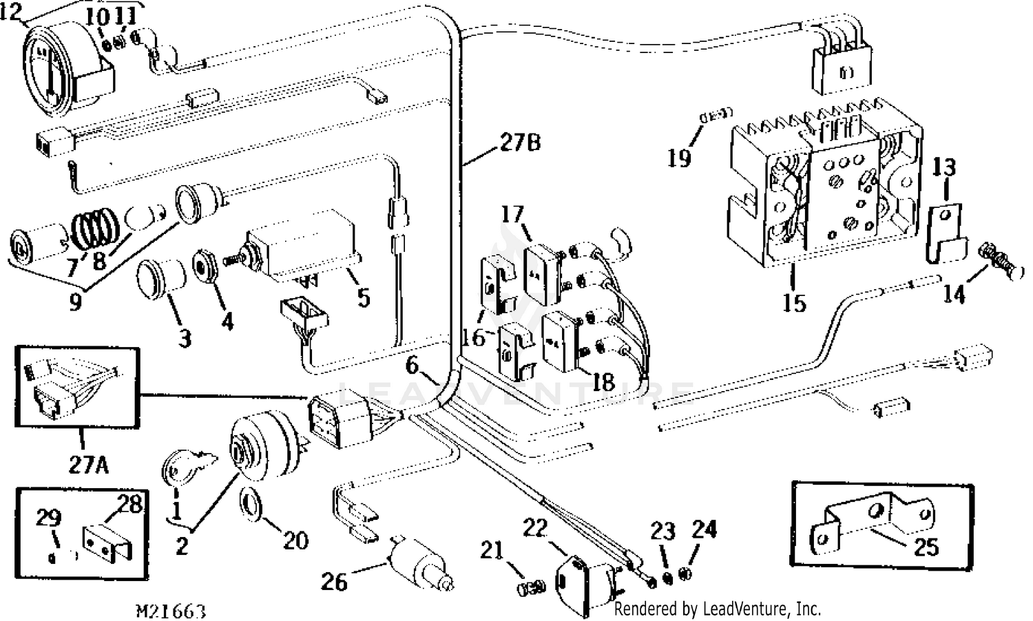
- Components: The diagram identifies the PTO switch, wiring harness, connectors, and other electrical components involved in the PTO system.
- Troubleshooting: The wiring diagram assists in diagnosing and resolving electrical malfunctions or damage within the PTO system, preventing downtime and ensuring optimal performance.
- Safety: Understanding the wiring diagram is essential for ensuring the safe operation of PTO-powered equipment, preventing electrical hazards and potential accidents.
- Maintenance: The diagram provides guidance for proper maintenance procedures, including inspection, cleaning, and replacement of electrical components as needed.
- Customization: For specialized applications or custom equipment configurations, the wiring diagram allows for modifications and adaptations to meet specific operational requirements.
- Compatibility: The wiring diagram ensures compatibility between the PTO switch and other electrical components within the John Deere equipment, preventing mismatched connections and potential damage.
- Documentation: The wiring diagram serves as a valuable documentation resource for technicians, operators, and maintenance personnel, providing a clear understanding of the PTO system’s electrical configuration.
In conclusion, the John Deere PTO switch wiring diagram encompasses various key aspects that are essential for the effective operation, maintenance, and troubleshooting of PTO-powered equipment. By understanding these aspects, technicians and operators can ensure the proper functioning, safety, and longevity of their machinery, maximizing productivity and minimizing downtime.
Purpose
The wiring diagram is a critical component of the John Deere PTO switch as it outlines the specific electrical connections and pathways that allow power to be transferred from the engine to external implements. Without a proper wiring diagram, technicians and operators may face challenges in understanding how the PTO system operates, which can lead to incorrect installations, malfunctions, or safety hazards.
Real-life examples of the importance of the wiring diagram within the PTO switch include:
- Troubleshooting: The wiring diagram provides a visual representation of the electrical system, making it easier to identify and resolve electrical issues or malfunctions within the PTO system.
- Maintenance: The diagram guides technicians during maintenance procedures, ensuring proper inspection, cleaning, and replacement of electrical components, which is crucial for maintaining optimal performance and longevity of the PTO system.
- Customization: For specialized applications or custom equipment configurations, the wiring diagram allows for modifications and adaptations to meet specific operational requirements, ensuring compatibility and safe operation of the PTO system.
Understanding the purpose and significance of the wiring diagram enables technicians and operators to effectively operate, maintain, and troubleshoot the PTO system. It promotes safe and efficient use of John Deere equipment, maximizes productivity, and minimizes downtime.
Components
Understanding the components involved in the John Deere PTO switch wiring diagram is crucial for effective maintenance, troubleshooting, and overall system comprehension. The diagram outlines the specific electrical connections and pathways, allowing technicians and operators to visualize and comprehend the system’s functionality.
- PTO Switch: The PTO switch is the central component that engages and disengages the power take-off, controlling the transfer of power from the engine to external implements. Understanding its wiring connections ensures proper operation and prevents potential malfunctions.
- Wiring Harness: The wiring harness consists of a bundle of wires that connect the PTO switch to other electrical components within the PTO system. It provides a structured and organized pathway for electrical signals, ensuring reliable communication and power distribution.
- Connectors: Connectors are crucial components that establish electrical connections between the PTO switch, wiring harness, and other electrical components. Proper mating and secure connections are essential for maintaining circuit integrity and preventing electrical faults.
- Additional Electrical Components: The wiring diagram may also include other electrical components such as relays, fuses, and sensors that play supporting roles in the PTO system. Understanding their functions and connections is vital for comprehensive troubleshooting and maintenance.
Through the identification and comprehension of these components, technicians and operators gain a deeper understanding of the John Deere PTO switch wiring diagram. This knowledge empowers them to perform accurate troubleshooting, ensure proper maintenance, and maximize the efficiency and reliability of PTO-powered equipment.
Troubleshooting
A John Deere PTO switch wiring diagram serves as an essential resource for diagnosing and resolving electrical malfunctions or damage within the PTO system. It provides a visual representation of the electrical connections and pathways, allowing technicians and operators to efficiently identify and troubleshoot any issues that may arise.
For instance, an electrical malfunction within the PTO system could manifest as intermittent power transfer, unexpected disengagement, or complete failure of the PTO. By utilizing the wiring diagram, technicians can systematically trace the electrical connections, identify the faulty component, and make the necessary repairs or replacements. This proactive approach minimizes downtime, ensures optimal performance, and prevents further damage to the PTO system or connected implements.
In summary, the troubleshooting aspect of the John Deere PTO switch wiring diagram empowers technicians and operators with the knowledge and tools to effectively maintain and repair PTO-powered equipment. By leveraging the wiring diagram, they can quickly diagnose and resolve electrical issues, maximizing uptime, productivity, and safety.
Safety
The John Deere PTO switch wiring diagram plays a critical role in ensuring the safe operation of PTO-powered equipment. Understanding the wiring diagram allows technicians and operators to identify and resolve electrical issues that could potentially lead to electrical hazards or accidents.
Real-life examples of how the wiring diagram contributes to safety include:
- Identifying faulty wiring or loose connections that could cause electrical fires.
- Troubleshooting electrical malfunctions that could lead to unexpected PTO engagement or disengagement, preventing injuries to operators or damage to equipment.
- Ensuring proper grounding of electrical components to prevent electrical shocks.
By understanding the wiring diagram, technicians and operators can proactively identify and address potential safety hazards, minimizing the risk of accidents and ensuring the safe operation of PTO-powered equipment.
In summary, the John Deere PTO switch wiring diagram is an essential tool for ensuring the safe operation of PTO-powered equipment. By providing a visual representation of the electrical connections and pathways, the wiring diagram empowers technicians and operators to identify and resolve electrical issues, preventing electrical hazards and potential accidents.
Maintenance
Within the context of the John Deere PTO switch wiring diagram, maintenance plays a crucial role in ensuring the optimal performance and longevity of PTO-powered equipment. The wiring diagram provides valuable guidance for proper maintenance procedures, empowering technicians and operators to effectively inspect, clean, and replace electrical components as needed.
- Electrical Component Inspection: The wiring diagram enables technicians to identify and inspect all electrical components within the PTO system, including the PTO switch, wiring harness, connectors, and other related components. Regular inspections allow for early detection of any signs of wear, damage, or corrosion, enabling timely maintenance interventions.
- Wiring Harness Maintenance: The wiring diagram serves as a guide for inspecting and maintaining the wiring harness, which carries electrical signals throughout the PTO system. Technicians can identify potential damage, loose connections, or insulation breaches, ensuring the integrity and reliability of electrical connections.
- Connector Maintenance: The wiring diagram assists in identifying and maintaining connectors, which establish electrical connections between different components. Proper cleaning and inspection of connectors prevent corrosion, ensure secure mating, and minimize electrical resistance, leading to optimal system performance.
- Component Replacement: When electrical components fail or become damaged, the wiring diagram guides technicians in identifying the correct replacement parts and provides instructions for safe and proper replacement procedures. This ensures the restoration of the PTO system to its optimal operating condition.
By following the maintenance guidance provided in the John Deere PTO switch wiring diagram, technicians and operators can proactively maintain PTO-powered equipment, preventing unexpected failures, extending equipment lifespan, and maximizing productivity.
Customization
Within the context of “John Deere Pto Switch Wiring Diagram”, customization plays a pivotal role in enabling specialized applications and tailored equipment configurations. The wiring diagram serves as a foundation for modifications and adaptations, empowering users to meet specific operational requirements.
- Custom Implement Integration: The wiring diagram allows for the integration of non-standard or custom-built implements, enabling the PTO system to accommodate unique functional requirements and specialized applications.
- Performance Optimization: Modifications to the wiring diagram can optimize PTO performance for specific tasks. For instance, adjusting wire gauges or adding relays can enhance power delivery and efficiency.
- Safety Enhancements: Customization through the wiring diagram allows for the implementation of additional safety features, such as interlocks or warning systems, tailored to specific operating environments or hazardous conditions.
- Remote Control Integration: The wiring diagram can be adapted to incorporate remote control functionality, enabling operators to engage or disengage the PTO from a distance, enhancing convenience and safety.
In summary, the customization aspect of the “John Deere Pto Switch Wiring Diagram” empowers users to modify and adapt the PTO system to meet specialized operational requirements, ranging from custom implement integration to enhanced safety features. This flexibility contributes to increased efficiency, improved performance, and tailored solutions for diverse applications.
Compatibility
Within the context of “John Deere PTO Switch Wiring Diagram”, compatibility plays a crucial role in ensuring the proper functioning and safety of PTO-powered equipment. The wiring diagram serves as the blueprint for establishing compatible electrical connections between the PTO switch and other components.
The absence of a proper wiring diagram can lead to mismatched connections, which can result in electrical malfunctions, damage to components, or even safety hazards. By providing a detailed representation of the electrical connections, the wiring diagram enables technicians and operators to:
- Identify the correct electrical connectors and terminals for each component.
- Verify the compatibility of wire gauges and types to ensure proper current carrying capacity.
- Confirm the correct polarity and grounding of electrical connections to prevent damage or interference.
Real-life examples of the importance of compatibility in the “John Deere PTO Switch Wiring Diagram” include:
- Preventing electrical shorts or fires caused by mismatched connections or incorrect wire gauges.
- Ensuring reliable operation of the PTO system by establishing proper communication between the PTO switch and other components.
- Maintaining the integrity of electrical components by preventing damage from incorrect voltage or current levels.
Understanding the concept of compatibility and its significance in the “John Deere PTO Switch Wiring Diagram” empowers technicians and operators to make informed decisions regarding electrical connections, ensuring the safe, efficient, and reliable operation of PTO-powered equipment.
Documentation
Within the context of “John Deere PTO Switch Wiring Diagram,” documentation plays a vital role in ensuring the proper installation, maintenance, and troubleshooting of PTO-powered equipment. The wiring diagram serves as a comprehensive reference for understanding the electrical connections and pathways involved in the PTO system.
- Comprehensive Reference: The wiring diagram provides a complete overview of the PTO system’s electrical configuration, enabling technicians and operators to visualize the connections between components, identify potential issues, and make informed decisions.
- Troubleshooting Guide: By studying the wiring diagram, technicians can methodically trace electrical circuits to diagnose faults, determine the root cause of malfunctions, and implement effective repairs.
- Maintenance Schedule: The wiring diagram can be used to create a customized maintenance schedule, ensuring that all electrical components are inspected and serviced at the appropriate intervals to prevent unexpected breakdowns and extend the lifespan of the equipment.
- Performance Optimization: Advanced users can leverage the wiring diagram to optimize PTO performance by identifying opportunities for electrical upgrades or modifications, such as installing relays or upgrading wire gauges to handle higher loads.
In summary, the documentation aspect of the “John Deere PTO Switch Wiring Diagram” empowers technicians, operators, and maintenance personnel with the knowledge and resources necessary to maintain, troubleshoot, and optimize PTO-powered equipment effectively. By providing a clear understanding of the electrical configuration, the wiring diagram contributes to the safe, efficient, and reliable operation of agricultural machinery.


Related Posts


