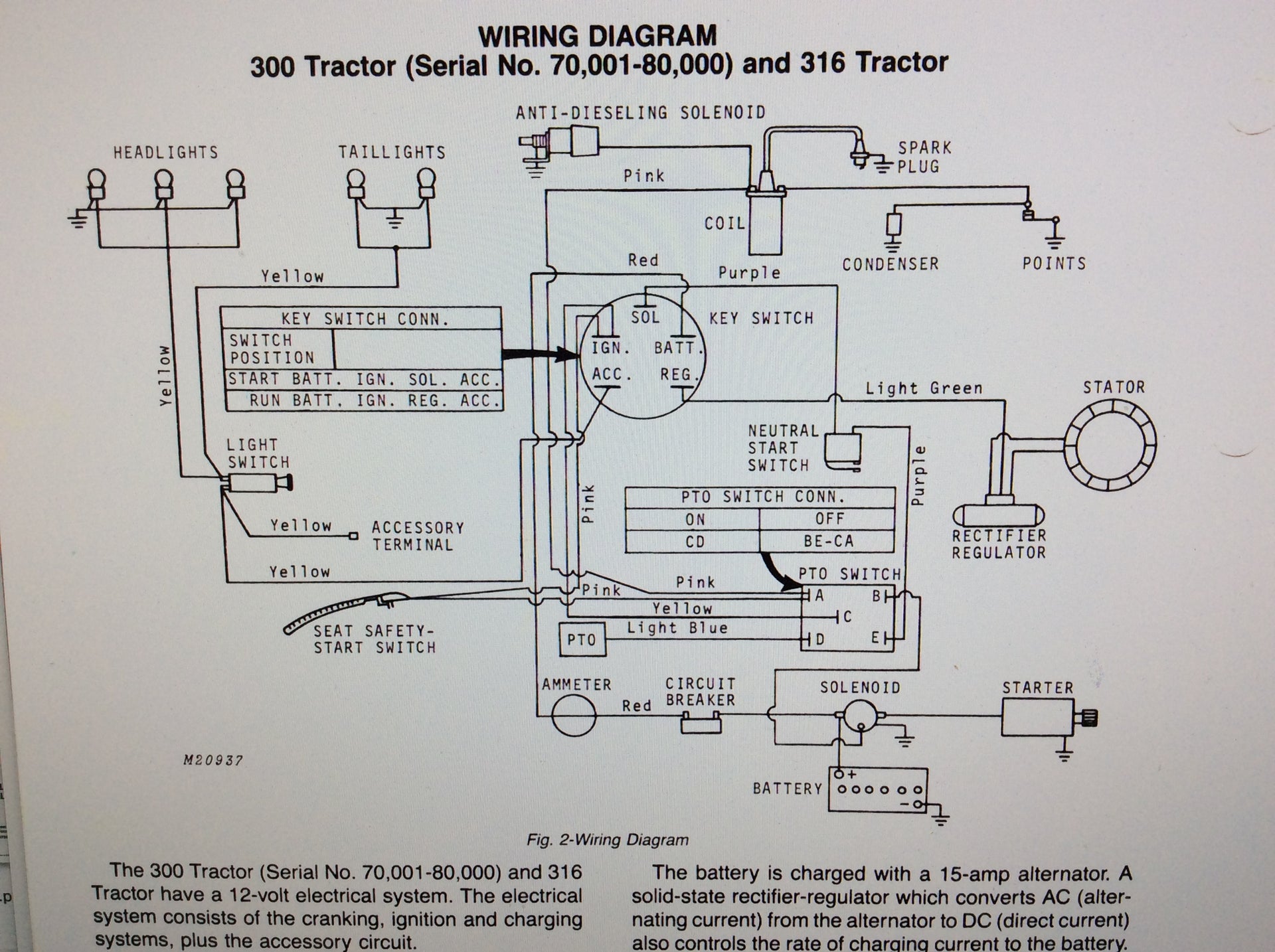
A John Deere Ignition Switch Wiring Diagram visually represents the electrical connections and components of the ignition system in John Deere equipment, providing a comprehensive guide for troubleshooting, repair, and maintenance. For instance, the diagram for a John Deere 4020 tractor outlines the wiring from the battery to the ignition switch, starter solenoid, and other vital parts.
These diagrams are invaluable for technicians and equipment operators, offering quick identification of electrical faults and ensuring safe and efficient operation. Their historical significance lies in the shift from mechanical to electrical ignition systems, with diagrams playing a crucial role in the smooth transition and widespread adoption of electrical ignition in John Deere machinery.
In this article, we delve into the intricacies of John Deere Ignition Switch Wiring Diagrams, exploring their technical aspects, practical applications, and ongoing relevance in modern agricultural equipment.
John Deere Ignition Switch Wiring Diagrams are indispensable tools for understanding and maintaining the electrical systems of John Deere equipment. These diagrams provide a visual representation of the electrical connections and components, making it easier to troubleshoot faults and perform repairs.
- Accuracy: Diagrams are meticulously crafted to ensure accurate representation of electrical connections.
- Comprehensiveness: Diagrams cover all essential components and wiring, providing a complete overview of the system.
- Clarity: Diagrams are designed to be easy to understand, with clear symbols and labeling.
- Troubleshooting: Diagrams enable technicians to quickly identify and resolve electrical faults.
- Repair: Diagrams provide step-by-step guidance for repairing electrical components.
- Maintenance: Diagrams assist in routine maintenance, such as wire harness inspection and replacement.
- Safety: Diagrams promote safe electrical practices by highlighting potential hazards.
- Training: Diagrams serve as valuable training aids for technicians and operators.
- Historical: Diagrams document the evolution of electrical systems in John Deere equipment.
In conclusion, John Deere Ignition Switch Wiring Diagrams are essential resources for anyone working with John Deere equipment. Their accuracy, comprehensiveness, and clarity make them invaluable tools for troubleshooting, repair, maintenance, and training. By understanding the key aspects of these diagrams, technicians and operators can ensure the safe and efficient operation of their equipment.
Accuracy
In the context of John Deere Ignition Switch Wiring Diagrams, accuracy is paramount. These diagrams form the foundation for troubleshooting, repair, and maintenance of electrical systems in John Deere equipment. Accurate diagrams ensure that technicians can rely on them for guidance, leading to correct diagnoses and effective repairs.
Consider a scenario where a diagram inaccurately depicts the connection between the ignition switch and the starter solenoid. A technician following this diagram may attempt to connect the wires incorrectly, potentially causing damage to the electrical system or even a safety hazard. Accurate diagrams eliminate such risks by providing a true representation of the intended electrical connections.
Real-life examples of accuracy in John Deere Ignition Switch Wiring Diagrams abound. The diagrams undergo rigorous review and testing by John Deere engineers to ensure their accuracy. Additionally, feedback from technicians and operators in the field helps identify and correct any discrepancies, further enhancing the accuracy of these diagrams.
The practical applications of accurate John Deere Ignition Switch Wiring Diagrams are vast. They empower technicians to quickly and confidently troubleshoot electrical faults, reducing downtime and maintenance costs. Accurate diagrams also promote safety by ensuring that electrical connections are made correctly, minimizing the risk of electrical fires or shocks.
In summary, the accuracy of John Deere Ignition Switch Wiring Diagrams is a critical component of their effectiveness. Accurate diagrams provide a reliable foundation for electrical system maintenance, troubleshooting, and repair, ensuring the safe and efficient operation of John Deere equipment.
Comprehensiveness
In the context of John Deere Ignition Switch Wiring Diagrams, comprehensiveness plays a vital role. These diagrams aim to provide a complete and accurate representation of the electrical system, including all essential components and wiring. The absence of even a single crucial detail can compromise the diagram’s effectiveness.
Consider a scenario where a diagram omits a critical wire connection. A technician relying on this diagram may overlook this connection during troubleshooting or repair, leading to persistent electrical faults. Comprehensiveness ensures that all essential elements are included, minimizing the risk of such omissions.
Real-life examples of comprehensive John Deere Ignition Switch Wiring Diagrams abound. These diagrams are meticulously crafted by John Deere engineers to include all necessary components, such as the ignition switch, starter solenoid, battery, and various sensors. Additionally, they depict all wiring connections, including color-coding and wire gauge information.
The practical applications of comprehensive John Deere Ignition Switch Wiring Diagrams are significant. They empower technicians to quickly and accurately identify and resolve electrical faults. By providing a complete overview of the system, these diagrams enable technicians to trace electrical circuits, locate faulty components, and make informed repair decisions.
In summary, comprehensiveness is a critical component of John Deere Ignition Switch Wiring Diagrams. Comprehensive diagrams ensure that all essential components and wiring are represented, enabling technicians to effectively troubleshoot, repair, and maintain electrical systems in John Deere equipment.
Clarity
In the context of John Deere Ignition Switch Wiring Diagrams, clarity is essential for effective use and accurate interpretation. Clear diagrams empower technicians to quickly and precisely identify components, trace electrical circuits, and troubleshoot faults, ensuring efficient maintenance and repair of John Deere equipment.
- Symbol Standardization: John Deere Ignition Switch Wiring Diagrams employ standardized symbols for electrical components, ensuring consistency and ease of understanding across different models and equipment types.
- Color-Coded Wiring: Wiring is represented with clear color-coding, enabling technicians to easily trace and identify individual circuits, simplifying troubleshooting and repair.
- Logical Layout: Diagrams are organized in a logical and intuitive manner, with components arranged in a way that reflects their physical placement and electrical connections, facilitating quick identification and comprehension.
- Detailed Labeling: Each component and wire is clearly labeled, providing specific information such as part numbers, wire gauge, and terminal connections, enhancing accuracy and reducing the risk of errors.
The clarity of John Deere Ignition Switch Wiring Diagrams directly translates into increased efficiency and accuracy in electrical system maintenance and repair. By providing clear and comprehensive visual representations of electrical circuits, these diagrams empower technicians to work confidently and effectively, minimizing downtime and maximizing the performance of John Deere equipment.
Troubleshooting
In the context of John Deere Ignition Switch Wiring Diagrams, the ability to troubleshoot electrical faults is paramount. John Deere Ignition Switch Wiring Diagrams serve as visual guides, providing a comprehensive overview of the electrical system, including component locations, wire connections, and circuit paths. This detailed representation empowers technicians to systematically identify and resolve electrical faults, ensuring efficient maintenance and repair of John Deere equipment.
Consider a scenario where an electrical fault arises in a John Deere tractor’s ignition system. Without a wiring diagram, the technician would have to manually trace each wire, inspect connections, and test components, a time-consuming and error-prone process. However, with a John Deere Ignition Switch Wiring Diagram in hand, the technician can quickly locate the affected circuit, identify potential fault points, and perform targeted troubleshooting, leading to a faster and more accurate diagnosis.
The practical applications of troubleshooting electrical faults using John Deere Ignition Switch Wiring Diagrams extend beyond efficiency and accuracy. By enabling technicians to quickly pinpoint and resolve electrical issues, these diagrams minimize downtime, reduce repair costs, and enhance the overall reliability of John Deere equipment. Furthermore, the ability to effectively troubleshoot electrical faults contributes to improved safety, as electrical faults left unattended can lead to hazardous situations, such as electrical fires or equipment malfunction.
In summary, the ability to troubleshoot electrical faults using John Deere Ignition Switch Wiring Diagrams is a critical component for effective maintenance and repair of John Deere equipment. These diagrams empower technicians with a comprehensive visual representation of the electrical system, enabling them to quickly identify and resolve electrical faults, minimizing downtime, reducing repair costs, and enhancing safety.
Repair
In the context of John Deere Ignition Switch Wiring Diagrams, the repair aspect plays a crucial role in maintaining and restoring the functionality of electrical components within John Deere equipment. These diagrams serve as indispensable guides, providing detailed instructions for repairing electrical components, ensuring efficient and accurate repairs.
Consider a scenario where a technician encounters a faulty ignition switch in a John Deere tractor. Without a wiring diagram, the technician would face challenges in identifying the root cause of the issue and performing the necessary repairs. However, with a John Deere Ignition Switch Wiring Diagram, the technician can pinpoint the exact location of the ignition switch, trace the electrical connections, and identify any potential faults. The diagram provides step-by-step instructions for repairing or replacing the ignition switch, ensuring a precise and efficient repair process.
Real-life examples of repair guidance in John Deere Ignition Switch Wiring Diagrams are abundant. These diagrams often include specific instructions for troubleshooting common electrical faults, such as open circuits, short circuits, and ground faults. They provide clear instructions on how to test components, identify faulty connections, and perform repairs using appropriate tools and techniques.
The practical applications of repair guidance in John Deere Ignition Switch Wiring Diagrams are significant. By providing technicians with clear and concise instructions, these diagrams enable them to repair electrical components quickly and effectively, minimizing downtime and maximizing the operational efficiency of John Deere equipment. Furthermore, these diagrams contribute to cost savings by reducing the need for extensive troubleshooting and trial-and-error repairs.
Maintenance
Within the context of John Deere Ignition Switch Wiring Diagrams, the aspect of maintenance plays a pivotal role in ensuring the longevity and optimal performance of John Deere equipment. These diagrams serve as valuable guides for routine maintenance tasks, including wire harness inspection and replacement, empowering technicians to proactively identify and address potential electrical issues.
- Wire Harness Inspection: John Deere Ignition Switch Wiring Diagrams provide a visual representation of the entire electrical system, allowing technicians to systematically inspect wire harnesses for damage, corrosion, or loose connections. By following the diagram, technicians can trace each wire and identify potential weak points, preventing electrical faults and ensuring reliable operation.
- Wire Harness Replacement: In cases where wire harnesses are damaged beyond repair, John Deere Ignition Switch Wiring Diagrams become indispensable for accurate and efficient replacement. The diagrams guide technicians in removing the old harness, routing the new harness correctly, and making proper electrical connections, minimizing downtime and ensuring proper functionality of the electrical system.
- Connector Inspection and Maintenance: Ignition Switch Wiring Diagrams also assist in the inspection and maintenance of electrical connectors. By identifying the location and type of each connector, technicians can visually inspect for corrosion, damage, or loose terminals, ensuring optimal electrical contact and preventing intermittent faults.
- Grounding System Inspection: John Deere Ignition Switch Wiring Diagrams provide a clear overview of the grounding system, enabling technicians to inspect grounding points for proper connection and resistance. By ensuring a solid electrical ground, technicians can prevent electrical noise, voltage fluctuations, and potential damage to sensitive electronic components.
In conclusion, the maintenance aspect of John Deere Ignition Switch Wiring Diagrams is integral to the effective upkeep and longevity of John Deere equipment. These diagrams empower technicians with the knowledge and guidance to perform routine maintenance tasks accurately and efficiently, minimizing downtime, preventing electrical issues, and ensuring the optimal performance of John Deere equipment.
Safety
In the context of John Deere Ignition Switch Wiring Diagrams, the focus on safety is paramount. These diagrams play a critical role in promoting safe electrical practices, ensuring the well-being of technicians and the integrity of John Deere equipment.
John Deere Ignition Switch Wiring Diagrams highlight potential hazards within the electrical system, such as high-voltage components, exposed terminals, and potential short circuits. By visually representing these hazards, the diagrams alert technicians to the risks involved and guide them in taking appropriate safety precautions. This can include wearing protective gear, using insulated tools, and following proper lockout/tagout procedures.
Real-life examples of safety hazards highlighted in John Deere Ignition Switch Wiring Diagrams abound. For instance, the diagrams clearly identify high-voltage components, such as the ignition coil and starter solenoid, indicating the need for caution when working around these areas. Additionally, the diagrams illustrate proper grounding practices, which are crucial for preventing electrical shocks and damage to sensitive electronic components.
The practical applications of understanding safety hazards highlighted in John Deere Ignition Switch Wiring Diagrams are far-reaching. By promoting safe electrical practices, these diagrams contribute to a safer work environment for technicians, reducing the risk of accidents and injuries. Furthermore, they help prevent damage to expensive electrical components and equipment, minimizing downtime and maintenance costs.
In conclusion, the safety aspect of John Deere Ignition Switch Wiring Diagrams is a critical component of their effectiveness. These diagrams empower technicians with the knowledge and guidance to identify and mitigate potential electrical hazards, ensuring the safety of individuals and the reliability of John Deere equipment.
Training
Within the comprehensive realm of John Deere Ignition Switch Wiring Diagrams, the aspect of training emerges as a crucial component. These diagrams play a pivotal role in educating technicians and operators, ensuring their proficiency in electrical system maintenance and repair.
- Visual Learning: Ignition Switch Wiring Diagrams provide a visual representation of the electrical system, enabling trainees to grasp complex concepts more easily. By studying the diagrams, technicians can visualize the flow of electricity, identify components, and understand their interconnections.
- Interactive Training: Diagrams facilitate interactive training sessions. Instructors can use them to guide trainees through troubleshooting scenarios, simulating real-life electrical faults. This hands-on approach reinforces learning and enhances problem-solving skills.
- Standardized Knowledge: Ignition Switch Wiring Diagrams promote standardized training across different training centers and regions. They ensure that technicians and operators receive consistent information, reducing the risk of errors and enhancing overall safety.
- Reference Material: Diagrams serve as valuable reference materials for technicians in the field. When faced with an unfamiliar electrical issue, technicians can consult the diagrams to refresh their memory, identify potential causes, and make informed decisions.
In conclusion, John Deere Ignition Switch Wiring Diagrams are indispensable training aids for technicians and operators. They foster visual learning, facilitate interactive training, standardize knowledge, and provide ongoing reference support. By equipping trainees with a deep understanding of electrical systems, these diagrams empower them to maintain and repair John Deere equipment confidently and efficiently.
Historical
Within the comprehensive realm of John Deere Ignition Switch Wiring Diagrams, the historical aspect emerges as a valuable lens through which we can trace the evolution of electrical systems in John Deere equipment. These diagrams serve as a testament to the advancements and innovations that have shaped the electrical architecture of John Deere machines over the decades.
- Evolution of Components: Ignition Switch Wiring Diagrams provide a glimpse into the evolution of electrical components used in John Deere equipment. By comparing diagrams from different eras, we can observe the transition from mechanical switches and relays to electronic control modules and sensors.
- Changing Circuitry: The diagrams also document the evolution of electrical circuitry. Early diagrams featured simple point-to-point wiring, while modern diagrams showcase complex networks with multiplexing and data buses.
- Integration of Technologies: Ignition Switch Wiring Diagrams reveal the increasing integration of technologies in John Deere equipment. Modern diagrams incorporate elements such as CAN (Controller Area Network) and GPS (Global Positioning System), reflecting the convergence of electrical and electronic systems.
- Diagnostics and Troubleshooting: Ignition Switch Wiring Diagrams have also played a crucial role in the development of diagnostic and troubleshooting techniques. By providing a visual representation of the electrical system, diagrams enable technicians to quickly identify and resolve electrical faults, reducing downtime and improving equipment reliability.
In conclusion, John Deere Ignition Switch Wiring Diagrams serve as valuable historical documents that chronicle the evolution of electrical systems in John Deere equipment. They provide insights into the changing components, circuitry, and technologies that have shaped the electrical architecture of these machines over time, aiding in the understanding, maintenance, and repair of John Deere equipment.


![[DIAGRAM] John Deere Ignition Switch Wiring Diagram](https://i0.wp.com/otos.yesterdaystractors.com/gallery/uptest/a243612.jpg?w=665&ssl=1)
Related Posts


