A John Deere D140 Wiring Diagram is a detailed schematic representation of the electrical system of a John Deere D140 lawn tractor. It provides a visual guide to the location, connection, and function of each electrical component within the tractor’s electrical system. For instance, the diagram can show the placement of the battery, starter motor, ignition coil, and various sensors and switches, as well as the wiring that connects them.
Wiring diagrams are crucial for troubleshooting electrical problems, as they allow technicians to trace the flow of electricity through the system and identify any faults or breaks in the wiring. They are also helpful for understanding the overall design and functionality of the electrical system and making modifications or upgrades to the system as needed. A significant historical development in wiring diagrams was the introduction of computer-aided design (CAD) software, which has made it possible to create detailed and accurate diagrams digitally.
This article will delve into the specifics of John Deere D140 Wiring Diagrams, providing a comprehensive guide for anyone looking to understand, troubleshoot, or modify the electrical system of their John Deere D140 lawn tractor.
Understanding the essential aspects of a John Deere D140 Wiring Diagram is crucial for anyone looking to maintain, troubleshoot, or modify the electrical system of their John Deere D140 lawn tractor. These aspects provide a comprehensive overview of the diagram’s purpose, components, and applications.
- Purpose: A visual guide to the electrical system.
- Components: Battery, starter motor, ignition coil, sensors, switches, wiring.
- Function: Trace electrical flow, identify faults, understand system design.
- Troubleshooting: Identify electrical problems, locate wiring issues.
- Modifications: Plan and execute upgrades to the electrical system.
- Installation: Guide for proper installation of electrical components.
- Safety: Ensure safe handling and maintenance of the electrical system.
- Compatibility: Specific to John Deere D140 lawn tractors.
- Format: Detailed schematic representation.
These aspects are interconnected and provide a holistic understanding of John Deere D140 Wiring Diagrams. For instance, knowing the purpose of the diagram helps in understanding its components and functions, while the troubleshooting aspect is essential for maintaining the electrical system’s health. Similarly, the compatibility aspect ensures that the diagram is specifically tailored to the John Deere D140 lawn tractor, providing accurate and relevant information for troubleshooting and maintenance.
Purpose
The purpose of a John Deere D140 Wiring Diagram is to provide a visual guide to the electrical system of a John Deere D140 lawn tractor. This diagram is a critical component of the tractor’s maintenance and repair documentation, as it allows users to understand the location, connection, and function of each electrical component within the system. Without a wiring diagram, troubleshooting electrical problems would be extremely difficult, if not impossible.
Real-life examples of how a John Deere D140 Wiring Diagram can be used include:
- Tracing the flow of electricity through the system to identify faults or breaks in the wiring.
- Understanding the overall design and functionality of the electrical system.
- Making modifications or upgrades to the electrical system, such as installing additional lighting or accessories.
The practical applications of understanding the purpose of a John Deere D140 Wiring Diagram are numerous. For instance, it can help users to:
- Diagnose and repair electrical problems quickly and efficiently.
- Make informed decisions about modifications or upgrades to the electrical system.
- Ensure the safe and proper operation of the electrical system.
In summary, a John Deere D140 Wiring Diagram is an essential tool for anyone who wants to understand, troubleshoot, or modify the electrical system of their John Deere D140 lawn tractor. By providing a visual guide to the electrical system, the wiring diagram makes it possible to quickly and easily identify and resolve electrical problems.
Components
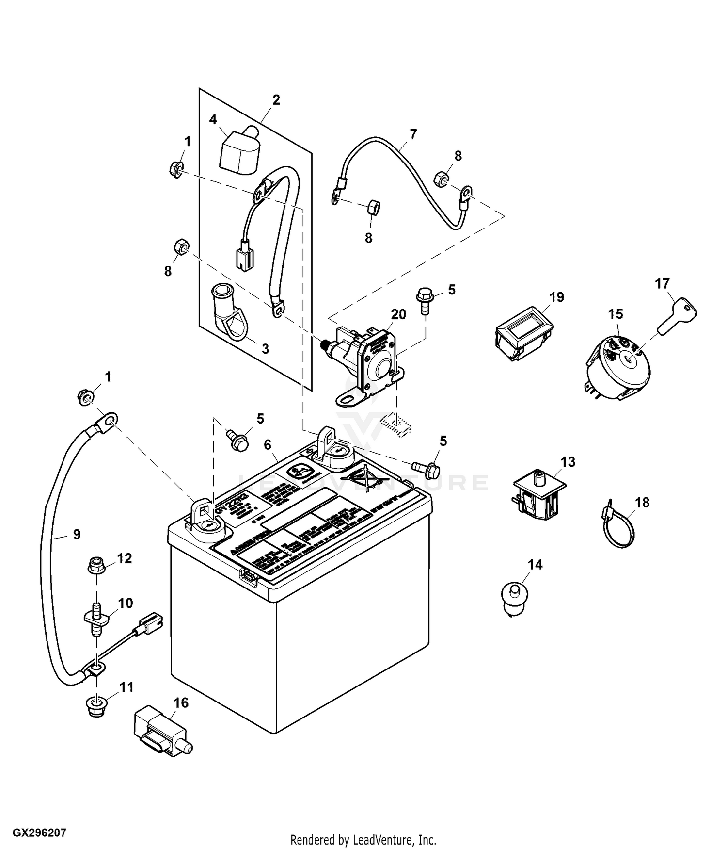
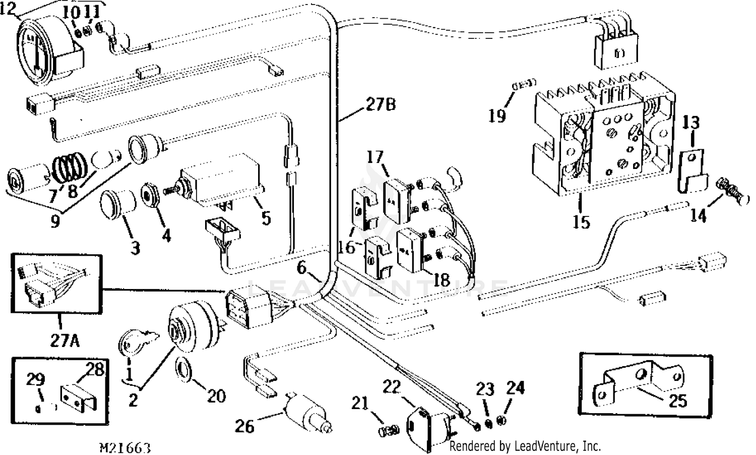
The components of a John Deere D140 electrical system, including the battery, starter motor, ignition coil, sensors, switches, and wiring, play a critical role in the overall functionality of the tractor. The John Deere D140 Wiring Diagram provides a visual representation of how these components are interconnected and how they work together to power the tractor’s electrical system.
The battery is the heart of the electrical system, providing the power to start the engine and operate the tractor’s electrical components. The starter motor uses the power from the battery to crank the engine and start it running. The ignition coil generates the high-voltage spark that ignites the air/fuel mixture in the engine’s cylinders. Sensors monitor various conditions within the engine and send signals to the tractor’s computer, which uses this information to adjust the engine’s performance. Switches allow the operator to control the tractor’s electrical components, such as the lights, wipers, and horn. Wiring connects all of these components together and allows electricity to flow throughout the system.
Understanding the relationship between the components of the John Deere D140 electrical system and the John Deere D140 Wiring Diagram is essential for troubleshooting and repairing electrical problems. By using the wiring diagram, technicians can trace the flow of electricity through the system and identify any faults or breaks in the wiring. This information can then be used to repair the problem and restore the electrical system to proper working order.
In summary, the components of the John Deere D140 electrical system are critical components of the John Deere D140 Wiring Diagram. By understanding the relationship between these components and the wiring diagram, technicians can troubleshoot and repair electrical problems quickly and efficiently.
Function
Within the context of a John Deere D140 Wiring Diagram, the function of tracing electrical flow, identifying faults, and understanding system design is paramount for maintaining and troubleshooting the electrical system. This function empowers individuals to comprehend the intricate network of electrical components, their interconnections, and the flow of electricity throughout the system.
- Component Analysis: The wiring diagram enables users to identify and locate specific electrical components, such as relays, fuses, and switches, and understand their role within the system.
- Circuit Tracing: By following the electrical pathways depicted in the diagram, users can trace the flow of electricity from the power source to various components and determine potential breaks or faults in the circuit.
- Fault Diagnosis: The wiring diagram provides a visual representation of the system, allowing users to isolate and diagnose electrical faults by identifying open circuits, short circuits, or grounding issues.
- System Comprehension: The diagram serves as a comprehensive guide to the electrical system’s design, aiding in understanding the interactions between components and the overall operation of the system.
Comprehending the function of tracing electrical flow, identifying faults, and understanding system design through the John Deere D140 Wiring Diagram is essential for effective troubleshooting, maintenance, and potential modifications to the electrical system. It empowers users with the knowledge and tools to diagnose and resolve electrical issues, ensuring the optimal performance and safety of their John Deere D140 lawn tractor.
Troubleshooting
Within the context of a John Deere D140 Wiring Diagram, troubleshooting electrical problems and locating wiring issues play a critical role in ensuring the optimal performance and safety of the lawn tractor. The diagram provides a comprehensive visual representation of the electrical system, empowering users to identify potential faults and resolve electrical problems.
- Component Analysis: The wiring diagram enables users to identify and locate specific electrical components, such as relays, fuses, and switches, and understand their role within the system. This knowledge is essential for troubleshooting electrical problems, as it allows users to isolate and test individual components to determine their functionality.
- Circuit Tracing: By following the electrical pathways depicted in the diagram, users can trace the flow of electricity from the power source to various components and determine potential breaks or faults in the circuit. This process is crucial for identifying wiring issues, as it allows users to pinpoint the exact location of the problem and make the necessary repairs.
- Fault Diagnosis: The wiring diagram provides a visual representation of the system, allowing users to isolate and diagnose electrical faults by identifying open circuits, short circuits, or grounding issues. This information is invaluable for troubleshooting, as it helps users to determine the root cause of the problem and develop a repair strategy.
- Preventive Maintenance: The John Deere D140 Wiring Diagram can also be used for preventive maintenance, as it allows users to identify potential weak points or areas that may require attention in the future. By proactively addressing these issues, users can minimize the risk of electrical problems and extend the lifespan of the electrical system.
Overall, the troubleshooting aspect of a John Deere D140 Wiring Diagram is an essential tool for maintaining and repairing the electrical system of a John Deere D140 lawn tractor. It empowers users to identify electrical problems, locate wiring issues, and understand the overall design of the system, ensuring the optimal performance and safety of their equipment.
Modifications
Within the realm of “John Deere D140 Wiring Diagram,” modifications encompass a significant aspect of maintaining and enhancing the electrical system of the John Deere D140 lawn tractor. This involves planning and executing upgrades to improve the performance, functionality, or aesthetics of the electrical system, often driven by specific requirements or preferences of the user.
- Component Enhancements: Upgrading individual electrical components, such as replacing halogen headlights with LED lights for improved visibility or installing a more powerful starter motor for quicker engine starts, can enhance the system’s capabilities.
- Accessory Integrations: Integrating additional electrical accessories, such as installing a sound system for entertainment or a GPS tracking device for security, requires careful planning and execution to ensure compatibility and proper functioning within the existing electrical system.
- Performance Optimization: Modifications aimed at optimizing the electrical system’s performance, such as upgrading the wiring harness to reduce resistance or installing a voltage regulator to stabilize electrical output, can enhance the overall efficiency and reliability of the system.
- Customization and Aesthetics: Modifications can also involve customizing the electrical system for aesthetic purposes, such as installing colored LED lights for visual appeal or adding decorative elements to enhance the overall appearance of the lawn tractor.
These facets of modifications underscore the versatility and adaptability of the John Deere D140 Wiring Diagram as a tool for tailoring the electrical system to specific needs and preferences. Whether it’s enhancing component performance, integrating new accessories, optimizing system efficiency, or customizing aesthetics, the wiring diagram provides the foundation for planning and executing successful electrical upgrades, ultimately extending the functionality and enjoyment of the John Deere D140 lawn tractor.
Installation
Within the context of “John Deere D140 Wiring Diagram,” the aspect of “Installation: Guide for proper installation of electrical components” holds paramount importance, ensuring the safe, efficient, and reliable operation of the electrical system. This comprehensive guide provides detailed instructions and visual representations for the proper installation of various electrical components, enabling users to execute electrical upgrades and repairs with confidence.
- Component Identification: The guide identifies and describes each electrical component, including its function, location, and connection points. This knowledge is essential for proper installation, as it allows users to correctly identify and connect the components.
- Wiring Techniques: The guide provides step-by-step instructions on wiring techniques, such as wire stripping, crimping, and soldering. These techniques are crucial for ensuring secure and reliable electrical connections.
- Safety Precautions: The guide emphasizes safety precautions to be observed during electrical installation, including the use of proper tools, wearing appropriate safety gear, and following electrical codes. These precautions minimize the risk of electrical hazards and ensure the safety of the user.
- Troubleshooting Tips: The guide includes troubleshooting tips to assist users in identifying and resolving common installation issues. These tips provide valuable guidance for resolving problems that may arise during the installation process.
By adhering to the guidelines provided in “Installation: Guide for proper installation of electrical components,” users can ensure the correct functioning of their electrical systems, prevent potential malfunctions or failures, and enhance the overall performance and longevity of their John Deere D140 lawn tractors. This comprehensive guide empowers users with the knowledge and confidence to undertake electrical installations and modifications, enabling them to customize and maintain their equipment effectively.
Safety
Within the context of a John Deere D140 Wiring Diagram, the paramount importance of safety cannot be overstated. The electrical system, comprising various components and wiring, poses potential hazards if not handled and maintained with appropriate care. The wiring diagram serves as a critical tool in ensuring the safe operation and servicing of the electrical system.
The John Deere D140 Wiring Diagram provides detailed visual instructions on the proper installation, connection, and maintenance of electrical components. By following these guidelines, users can minimize the risk of electrical hazards, such as short circuits, overloads, and electrical fires. The diagram empowers users with the knowledge to identify potential safety concerns, such as damaged wiring or loose connections, and take appropriate corrective actions.
Real-life examples of the safety-oriented features within the John Deere D140 Wiring Diagram include color-coded wires for easy identification, clear labeling of components, and warnings highlighting potential hazards. These features facilitate safe handling and maintenance, enabling users to work on the electrical system with confidence. The diagram also provides guidance on the use of proper tools and equipment, emphasizing the importance of wearing protective gear to prevent electrical shocks or burns.
The practical applications of understanding the connection between safety and the John Deere D140 Wiring Diagram extend beyond immediate electrical system maintenance. It fosters a culture of safety awareness among users, promoting responsible practices in all aspects of lawn tractor operation and maintenance. By incorporating safety considerations into the design and usage of the wiring diagram, John Deere empowers users to prioritize their safety and the longevity of their equipment.
Compatibility
Within the realm of “John Deere D140 Wiring Diagram,” the aspect of “Compatibility: Specific to John Deere D140 lawn tractors” assumes paramount importance, ensuring that the information and guidance provided within the diagram are directly applicable and relevant to the electrical systems of John Deere D140 lawn tractors. This compatibility encompasses several key facets:
- Specific Components: The John Deere D140 Wiring Diagram is meticulously designed to align with the specific electrical components and configurations found in John Deere D140 lawn tractors. This ensures that the diagram accurately reflects the placement, connections, and functionality of electrical components within these tractors.
- Electrical System Design: The diagram takes into account the unique design of the John Deere D140 lawn tractor’s electrical system, including its voltage, amperage, and grounding configurations. This compatibility ensures that the diagram provides accurate guidance for troubleshooting, repairs, and modifications specific to these tractors.
- Real-Life Applications: The John Deere D140 Wiring Diagram is extensively tested and validated to ensure its accuracy and effectiveness in real-life scenarios involving John Deere D140 lawn tractors. This compatibility guarantees that the diagram is a reliable resource for technicians, mechanics, and owners working on these tractors.
- Maintenance and Troubleshooting: The compatibility of the John Deere D140 Wiring Diagram with John Deere D140 lawn tractors enables efficient maintenance and troubleshooting procedures. By referencing the diagram, users can quickly identify and resolve electrical issues, ensuring optimal performance and safety of their tractors.
In summary, “Compatibility: Specific to John Deere D140 lawn tractors” is a crucial aspect of the John Deere D140 Wiring Diagram, ensuring its accuracy, relevance, and utility for maintaining, troubleshooting, and modifying the electrical systems of John Deere D140 lawn tractors. This compatibility empowers users to work confidently on their tractors, ensuring their optimal performance and longevity.
Format
Within the context of “John Deere D140 Wiring Diagram,” the “Format: Detailed schematic representation” plays a critical role in conveying the intricate details of the tractor’s electrical system. A schematic representation employs a standardized set of symbols and lines to depict the electrical components, their connections, and the flow of electricity within the system.
The detailed nature of this format is paramount for effective troubleshooting and repairs. It allows users to trace the electrical pathways, identify potential breaks or faults, and understand the interrelationships between different components. The schematic representation provides a comprehensive visual guide, enabling users to pinpoint specific issues and develop targeted solutions.
Real-life examples of the “Format: Detailed schematic representation” within the “John Deere D140 Wiring Diagram” include:
- Color-coded wires and symbols to differentiate between different types of electrical components and their functions.
- Clear labeling of components, such as relays, fuses, and switches, to facilitate easy identification and troubleshooting.
- Logical organization of the diagram, grouping related components and connections to enhance clarity and understanding.
The practical applications of understanding the connection between “Format: Detailed schematic representation” and “John Deere D140 Wiring Diagram” extend beyond immediate electrical system maintenance. It fosters a deeper comprehension of the tractor’s electrical system, enabling users to make informed decisions about modifications or upgrades. The detailed schematic representation empowers users to confidently navigate the complexities of the electrical system, ensuring the optimal performance and longevity of their John Deere D140 lawn tractors.


Related Posts


