A John Deere 4020 12 Volt Wiring Diagram is a schematic representation of the electrical system of a John Deere 4020 tractor, specifically those models powered by a 12-volt electrical system. This diagram serves as a guide, providing detailed information about the wiring connections, component locations, and electrical troubleshooting procedures for the tractor.
Having an accurate and up-to-date wiring diagram is crucial for maintaining, repairing, or modifying the electrical system of a John Deere 4020 tractor. It simplifies the identification of electrical faults, facilitates the installation of additional electrical accessories, and helps ensure the proper functioning of the tractor’s lighting, ignition, starting, and other electrical components. One significant historical development in wiring diagrams was the transition from paper-based diagrams to digital formats, making them more accessible and easier to use.
This article delves into the key components of a John Deere 4020 12 Volt Wiring Diagram, explains how to interpret and use it effectively, and provides practical tips for troubleshooting electrical issues using the diagram. By gaining a clear understanding of the wiring diagram, owners and operators of John Deere 4020 tractors can confidently maintain and repair their tractors, ensuring optimal performance and reliability.
The John Deere 4020 12 Volt Wiring Diagram serves as a comprehensive guide to the electrical system of the John Deere 4020 tractor. Understanding the essential aspects of this wiring diagram is crucial for maintaining, repairing, and modifying the tractor’s electrical system effectively.
- Components: Identifying and locating electrical components, such as batteries, starters, alternators, and switches.
- Connections: Tracing wire connections between components, ensuring proper current flow and functionality.
- Troubleshooting: Using the diagram to diagnose electrical faults and identify potential issues.
- Modifications: Making informed decisions about adding electrical accessories or modifying the existing system.
- Safety: Understanding the electrical system layout for safe maintenance and repair procedures.
- Power Distribution: Mapping the flow of electrical power from the battery to various components.
- Grounding: Identifying proper grounding points to ensure electrical stability and prevent malfunctions.
- Symbols: Interpreting electrical symbols used in the diagram to represent different components and connections.
- Wire Gauge: Understanding wire gauge specifications to ensure proper current-carrying capacity.
- Color Coding: Recognizing color-coded wires for easier identification and tracing.
These aspects provide a comprehensive understanding of the John Deere 4020 12 Volt Wiring Diagram, empowering owners and operators to maintain and repair their tractors with confidence. By using the diagram effectively, they can troubleshoot electrical problems, make informed modifications, and ensure the optimal performance and reliability of their tractors.
Components
In the context of a John Deere 4020 12 Volt Wiring Diagram, identifying and locating electrical components accurately is a critical foundation for understanding the electrical system of the tractor. The wiring diagram serves as a map, providing a visual representation of the electrical connections between various components. Without a clear understanding of the components and their locations, it becomes challenging to troubleshoot electrical issues, make modifications, or perform maintenance tasks effectively.
The John Deere 4020 12 Volt Wiring Diagram includes symbols and labels that represent each electrical component. By matching these symbols and labels to the actual components in the tractor, one can gain a comprehensive understanding of the electrical system layout. For example, the diagram shows the location of the battery, which is the main power source for the tractor. It also indicates the location of the starter, which is responsible for cranking the engine, and the alternator, which generates electricity to recharge the battery and power the electrical system while the engine is running.
Practical applications of this understanding include the ability to quickly identify and replace a faulty component. By referring to the wiring diagram, one can trace the electrical connections to locate the specific component that is causing problems. This can save time and effort compared to randomly checking components without a clear understanding of their locations. Additionally, when adding electrical accessories or modifying the existing system, the wiring diagram provides guidance on where to connect the new components and how to integrate them into the electrical system properly.
In summary, the ability to identify and locate electrical components is a crucial aspect of using a John Deere 4020 12 Volt Wiring Diagram effectively. By understanding the locations and functions of the various components, owners and operators can maintain, troubleshoot, and modify the electrical system of their tractors with greater confidence and efficiency.
Connections
In the context of a John Deere 4020 12 Volt Wiring Diagram, tracing wire connections between components is crucial for ensuring proper current flow and overall functionality of the electrical system. The wiring diagram serves as a visual guide, providing a detailed representation of the electrical connections between various components, such as batteries, starters, alternators, and switches.
Understanding these connections is essential for troubleshooting electrical issues, making modifications, and maintaining the tractor’s electrical system effectively. By tracing the wire connections, one can identify loose or damaged wires, faulty connections, or incorrect wiring, which can lead to electrical malfunctions or even safety hazards.
Real-life examples of tracing wire connections within a John Deere 4020 12 Volt Wiring Diagram include:
- Identifying the cause of a non-functioning headlight by tracing the wires from the headlight switch to the headlight.
- Locating a short circuit by tracing the wires from the battery to the component causing the short.
- Adding an electrical accessory, such as a work light, by tracing the wires from the power source to the desired location.
Harnessing this understanding, owners and operators of John Deere 4020 tractors can maintain, troubleshoot, and modify their tractors’ electrical systems with greater confidence and efficiency. The wiring diagram empowers them to diagnose electrical problems, make informed decisions about modifications, and ensure the optimal performance and reliability of their tractors.
In summary, “Connections: Tracing wire connections between components, ensuring proper current flow and functionality” is a critical component of the John Deere 4020 12 Volt Wiring Diagram. By understanding and tracing these connections accurately, one can effectively maintain, troubleshoot, and modify the electrical system, ensuring the smooth operation and safety of the tractor.
Troubleshooting
When dealing with the electrical system of a John Deere 4020 tractor, accurate troubleshooting is crucial to ensure optimal performance and to prevent potential hazards. The John Deere 4020 12 Volt Wiring Diagram serves as an indispensable tool in this regard, providing a visual representation of the electrical connections and components.
-
Identifying Faulty Components:
The wiring diagram enables the identification of faulty components by tracing the electrical connections and identifying points of failure. This can be particularly useful when dealing with intermittent electrical issues or when multiple components are involved.
-
Tracing Electrical Shorts:
Electrical shorts can be a major source of electrical problems. The wiring diagram allows for the tracing of electrical circuits to identify potential short circuits, which can lead to blown fuses, damaged components, or even electrical fires.
-
Verifying Power Flow:
The diagram helps verify the flow of electrical power throughout the system. By tracing the connections from the battery to various components, one can ensure that power is reaching the intended destinations and that there are no breaks in the circuit.
-
Assessing Modifications:
When modifying the electrical system, the wiring diagram is essential for assessing the impact of changes. By comparing the original diagram to the modified system, potential conflicts or compatibility issues can be identified, ensuring a safe and reliable electrical system.
Effectively using the John Deere 4020 12 Volt Wiring Diagram for troubleshooting requires a thorough understanding of electrical principles and familiarity with the specific components of the tractor’s electrical system. By interpreting the diagram accurately and applying it to real-life scenarios, owners and operators of John Deere 4020 tractors can diagnose electrical faults, identify potential issues, and ensure the proper functioning of their tractors’ electrical systems.
Modifications
When dealing with the electrical system of a John Deere 4020 tractor, modifications are often necessary to enhance functionality, add new features, or repair existing components. The John Deere 4020 12 Volt Wiring Diagram becomes a crucial tool in this scenario, providing a visual representation of the electrical connections and components.
-
Component Compatibility:
Before adding electrical accessories or modifying the existing system, it is essential to ensure compatibility with the tractor’s electrical system. The wiring diagram allows for the assessment of voltage, amperage, and other electrical characteristics to ensure that new components can be integrated safely and effectively.
-
Load Analysis:
The wiring diagram helps determine the electrical load of the system, including the power consumption of existing and potential new components. This analysis ensures that the electrical system can handle the additional load without overloading wires, fuses, or other components.
-
Circuit Protection:
When modifying the electrical system, proper circuit protection is crucial. The wiring diagram aids in identifying suitable locations for fuses or circuit breakers, ensuring that electrical faults or overloads do not cause damage to the system or potential fire hazards.
-
Real-Life Examples:
Adding work lights to enhance visibility during nighttime operations or installing a GPS system for precision farming are practical examples of modifications that can be effectively planned and executed using the John Deere 4020 12 Volt Wiring Diagram.
By utilizing the John Deere 4020 12 Volt Wiring Diagram, owners and operators can make informed decisions about electrical modifications, ensuring that these changes are compatible, safe, and do not compromise the overall integrity and performance of the tractor’s electrical system.
Safety
When it comes to maintaining and repairing the electrical system of a John Deere 4020 tractor, safety should be the topmost priority. Understanding the electrical system layout is a critical component of ensuring safe maintenance and repair procedures, which is where the John Deere 4020 12 Volt Wiring Diagram plays a pivotal role.
The wiring diagram provides a comprehensive visual representation of the electrical system, including the location of components, wire connections, and power flow. By studying the diagram, technicians and operators can gain a thorough understanding of the electrical system’s operation, potential hazards, and proper safety protocols. This knowledge enables them to identify and isolate electrical faults, perform repairs, and make modifications safely.
Real-life examples of how the John Deere 4020 12 Volt Wiring Diagram contributes to safety include:
- Identifying the correct fuse or circuit breaker to isolate a faulty circuit, preventing electrical fires or damage to components.
- Locating and repairing damaged wires or connectors, eliminating potential short circuits and electrical shocks.
- Properly connecting new electrical components or accessories, ensuring compatibility and preventing overloading or malfunctions.
In summary, understanding the electrical system layout through the John Deere 4020 12 Volt Wiring Diagram is paramount for safe maintenance and repair procedures. It empowers technicians and operators with the knowledge to work on the electrical system confidently, minimize risks, and prevent accidents.
Power Distribution
Within the context of a “John Deere 4020 12 Volt Wiring Diagram”, understanding the power distribution system is critical for ensuring the proper functioning and reliability of the tractor’s electrical components. This involves mapping the flow of electrical power from the battery, which serves as the central power source, to the various electrical components and systems.
-
Battery:
The battery is the heart of the electrical system and stores electrical energy, providing power to start the engine and operate electrical components when the engine is not running.
-
Charging System:
The charging system, typically consisting of an alternator and voltage regulator, generates electrical power and recharges the battery while the engine is running, ensuring a continuous supply of electricity.
-
Fuses and Circuit Breakers:
Fuses and circuit breakers act as protective devices, safeguarding electrical circuits from overloads or short circuits that could damage components or cause electrical fires.
-
Wiring Harness:
The wiring harness serves as the network of electrical wires that connect the battery, charging system, fuses, and electrical components, facilitating the flow of electricity throughout the tractor.
Understanding power distribution in the “John Deere 4020 12 Volt Wiring Diagram” empowers users to troubleshoot electrical issues, assess the impact of modifications, and ensure the safe and efficient operation of the tractor’s electrical system.
Grounding
In the context of a John Deere 4020 12 Volt Wiring Diagram, understanding grounding principles is crucial for ensuring the stable and reliable operation of the tractor’s electrical system. Grounding refers to the intentional connection of an electrical circuit to the chassis or frame of the tractor, providing a common reference point for electrical current and preventing voltage fluctuations or malfunctions.
The John Deere 4020 12 Volt Wiring Diagram clearly indicates the designated grounding points within the electrical system. These points are typically located at the battery’s negative terminal, the engine block, and the tractor’s frame. By connecting the electrical components to these grounding points, a complete circuit is established, allowing for the proper flow of electrical current and the dissipation of excess voltage. Failure to ensure proper grounding can lead to a variety of electrical issues, including voltage spikes, component damage, and even electrical fires.
Real-life examples of grounding within the John Deere 4020 12 Volt Wiring Diagram include the connection of the headlights to the tractor’s frame, the grounding of the starter motor to the engine block, and the use of grounding straps to connect various electrical components to the chassis. By following the wiring diagram and adhering to proper grounding practices, owners and operators can ensure that the tractor’s electrical system functions as intended, minimizing the risk of electrical problems and maintaining optimal performance.
In summary, grounding is a fundamental aspect of electrical system design and maintenance, and the John Deere 4020 12 Volt Wiring Diagram provides valuable guidance on identifying and utilizing proper grounding points. Understanding and applying grounding principles is essential for ensuring electrical stability, preventing malfunctions, and extending the lifespan of the tractor’s electrical components.
Symbols
In the context of a John Deere 4020 12 Volt Wiring Diagram, understanding the electrical symbols used to represent various components and connections is essential for effectively interpreting and utilizing the diagram. These symbols serve as a common language, allowing users to visualize and comprehend the complex electrical system of the tractor.
-
Component Symbols:
Component symbols represent the different electrical components used in the tractor, such as batteries, switches, motors, and sensors. Understanding these symbols enables users to identify and locate specific components within the diagram.
-
Connection Symbols:
Connection symbols indicate how the electrical components are interconnected. These symbols include lines, arrows, and dots, each representing a specific type of connection, such as power supply, ground, or data transfer.
-
Wire Type Symbols:
Wire type symbols differentiate between different types of electrical wires used in the tractor. These symbols indicate the wire’s gauge, insulation, and color coding, providing crucial information for proper installation and maintenance.
-
Grounding Symbols:
Grounding symbols represent the points in the electrical system that are connected to the tractor’s frame or chassis. Understanding these symbols is vital for ensuring proper grounding, which is essential for electrical safety and system stability.
Interpreting electrical symbols accurately is not only crucial for understanding the John Deere 4020 12 Volt Wiring Diagram but also for effectively troubleshooting electrical issues, making modifications, and ensuring the proper functioning of the tractor’s electrical system. By mastering the language of electrical symbols, owners and operators can confidently navigate the complexities of their tractor’s electrical system and maintain its optimal performance.
Wire Gauge
Within the context of a John Deere 4020 12 Volt Wiring Diagram, understanding wire gauge specifications is crucial for ensuring the proper functioning and safety of the tractor’s electrical system. Wire gauge refers to the thickness or diameter of an electrical wire, which directly impacts its current-carrying capacity.
Properly sized wires are essential for handling the electrical load of the tractor’s components without overheating or causing voltage drops. The John Deere 4020 12 Volt Wiring Diagram specifies the appropriate wire gauge for each electrical circuit, considering factors such as the current draw of the connected components and the length of the wire runs.
Real-life examples of wire gauge considerations within a John Deere 4020 12 Volt Wiring Diagram include:
- Using thicker gauge wire for high-current circuits, such as those supplying power to the starter motor or headlights.
- Using thinner gauge wire for low-current circuits, such as those controlling indicator lights or sensors.
- Ensuring that wire gauge is adequate for the length of the circuit to minimize voltage loss and prevent overheating.
Understanding wire gauge specifications and adhering to the recommendations provided in the John Deere 4020 12 Volt Wiring Diagram is essential for the safe and reliable operation of the tractor. By using appropriately sized wires, owners and operators can prevent electrical fires, ensure optimal component performance, and extend the lifespan of the electrical system.
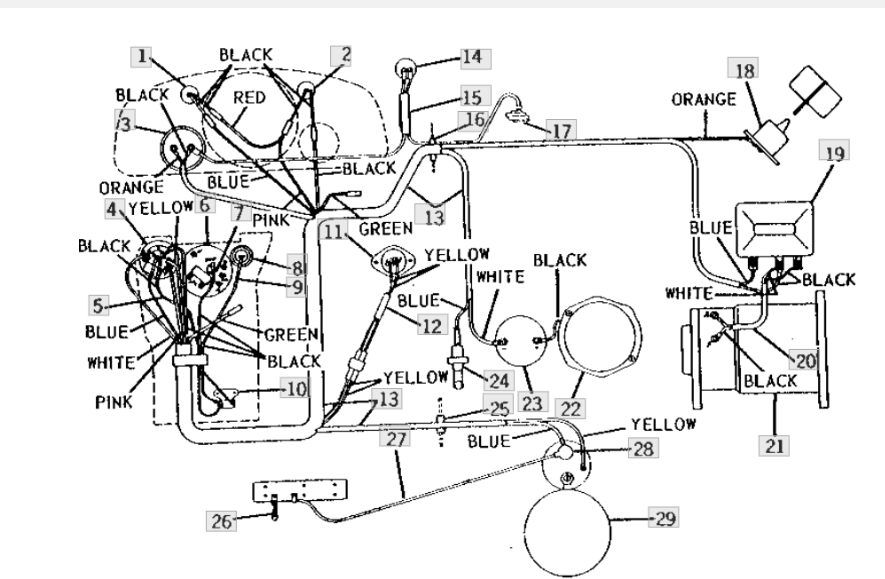
Color Coding
In the context of a John Deere 4020 12 Volt Wiring Diagram, color coding plays a crucial role in simplifying the identification and tracing of electrical wires. By assigning specific colors to different types of wires or circuits, the wiring diagram provides a visual cue that helps users quickly distinguish between them.
Color coding is a critical component of the John Deere 4020 12 Volt Wiring Diagram because it enables technicians and operators to efficiently troubleshoot electrical issues, make modifications, and perform maintenance tasks. Without color coding, tracing wires through the complex network of the tractor’s electrical system would be a time-consuming and error-prone process.
Real-life examples of color coding within the John Deere 4020 12 Volt Wiring Diagram include:
- Red wires typically indicate power supply circuits.
- Black wires are commonly used for ground connections.
- Blue wires may represent control circuits or data transfer.
By adhering to these color-coding conventions, the wiring diagram provides a consistent and intuitive representation of the electrical system, making it easier to navigate and understand.
The practical application of color coding in the John Deere 4020 12 Volt Wiring Diagram extends beyond simplified identification. It also enhances safety by allowing users to quickly identify and isolate potential electrical hazards. For example, the distinct color coding of power supply wires helps technicians avoid accidental contact with live circuits.
In conclusion, color coding is an essential aspect of the John Deere 4020 12 Volt Wiring Diagram. It provides a structured and efficient way to identify and trace electrical wires, simplifies troubleshooting and maintenance procedures, and contributes to the overall safety and reliability of the tractor’s electrical system.


Related Posts


