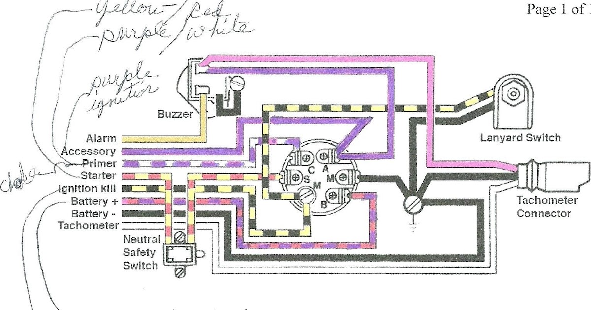
John Deere 318 Wiring Diagram is a technical document illustrates the electrical connections and components within a John Deere 318 lawn tractor. It serves as a visual guide for diagnosing electrical issues, installing new components, and understanding the tractor’s electrical system.
The wiring diagram helps users identify the location of electrical components, such as switches, relays, fuses, and wiring harnesses. It also provides information about the voltage and amperage requirements of each component, ensuring proper installation and operation of the electrical system. Additionally, the diagram can aid in troubleshooting electrical problems, enabling users to quickly locate faulty connections or components.
John Deere 318 Wiring Diagram is a valuable resource for lawn tractor owners, technicians, and enthusiasts alike, empowering them to maintain and repair their machines effectively and efficiently.
A John Deere 318 Wiring Diagram is a visual representation of the electrical connections and components within a John Deere 318 lawn tractor. As a noun, it serves as a comprehensive guide for understanding, maintaining, and troubleshooting the electrical system of the tractor. Key aspects of the John Deere 318 Wiring Diagram include:
- Electrical Components: It illustrates the location and function of electrical components such as switches, relays, fuses, and solenoids.
- Wiring Harness: It shows the routing and connections of the electrical wiring harness throughout the tractor.
- Voltage and Amperage Requirements: It specifies the voltage and amperage requirements of each electrical component.
- Circuit Protection: It outlines the fuses and circuit breakers responsible for protecting the electrical system from overloads and short circuits.
- Troubleshooting Guide: It provides a systematic approach to diagnosing and repairing electrical problems.
- Maintenance Instructions: It includes guidelines for maintaining the electrical system, including regular inspections and cleaning.
- Safety Precautions: It emphasizes the importance of following safety precautions when working on the electrical system.
- Warranty Information: It may include information about the warranty coverage for electrical components and repairs.
These aspects collectively provide a comprehensive understanding of the John Deere 318 Wiring Diagram, enabling users to effectively maintain, troubleshoot, and repair the electrical system of their lawn tractor.
Electrical Components
Understanding the electrical components of a John Deere 318 lawn tractor is crucial for maintaining and troubleshooting its electrical system. The John Deere 318 Wiring Diagram provides a detailed illustration of these components, including their location and function. Key electrical components found in the wiring diagram include:
- Switches: Switches control the flow of electricity in the circuit. They are typically used to turn components on or off, such as the ignition switch or headlights.
- Relays: Relays are electromagnetic switches that use a small amount of current to control a larger amount of current. They are often used to protect sensitive electrical components from high currents or to provide isolation between different circuits.
- Fuses: Fuses are designed to protect electrical circuits from overloads by breaking the circuit if the current exceeds a safe level. This helps prevent damage to electrical components and potential fires.
- Solenoids: Solenoids are electromagnetic devices that convert electrical energy into mechanical energy. They are commonly used to engage the starter motor or to operate hydraulic valves.
By understanding the location and function of these electrical components, users can effectively diagnose and repair electrical problems, ensuring the proper operation of their John Deere 318 lawn tractor.
Wiring Harness
The wiring harness is a crucial component of the John Deere 318 Wiring Diagram, providing a visual representation of the electrical connections and components within the lawn tractor. It serves as a comprehensive guide for understanding, maintaining, and troubleshooting the electrical system.
- Electrical Components: The wiring harness connects various electrical components, including switches, relays, fuses, and solenoids, allowing them to communicate and function as a cohesive system.
- Power Distribution: The wiring harness distributes electrical power from the battery to the various components of the tractor, ensuring that they receive the necessary voltage and amperage to operate.
- Circuit Protection: The wiring harness incorporates fuses and circuit breakers to protect the electrical system from overloads and short circuits, preventing damage to components and potential electrical fires.
- Maintenance and Repair: The wiring harness simplifies maintenance and repair tasks by providing a clear visual representation of the electrical connections. This enables technicians to quickly identify and access faulty components, reducing downtime and repair costs.
In conclusion, the wiring harness aspect of the John Deere 318 Wiring Diagram is essential for understanding the flow of electricity within the lawn tractor. It provides a comprehensive view of the electrical connections, enabling users to maintain, troubleshoot, and repair the electrical system effectively, ensuring the optimal performance of the tractor.
Voltage and Amperage Requirements
The voltage and amperage requirements of each electrical component are crucial specifications within the John Deere 318 Wiring Diagram. Understanding these requirements is essential for ensuring the proper functioning and longevity of the electrical system. The wiring diagram provides detailed information about the voltage and amperage needs of each component, enabling users to select and install compatible components and avoid potential electrical issues.
For instance, the wiring diagram specifies that the ignition coil requires 12 volts of power. If a lower voltage is supplied, the ignition coil may not generate a strong enough spark to ignite the engine. Conversely, if a higher voltage is supplied, it could damage the ignition coil and other electrical components. Similarly, the wiring diagram indicates that the starter motor draws a high amperage during cranking. Using a battery or charging system with insufficient amperage capacity could result in a slow or failed engine start.
By adhering to the voltage and amperage requirements specified in the John Deere 318 Wiring Diagram, users can ensure that each electrical component receives the appropriate power to operate effectively and avoid potential damage. This understanding is critical for maintaining a reliable and efficient electrical system, maximizing the performance and lifespan of the lawn tractor.
Circuit Protection
Within the John Deere 318 Wiring Diagram, circuit protection is a critical component responsible for safeguarding the electrical system from potential damage caused by overloads and short circuits. Fuses and circuit breakers serve as essential protective devices, ensuring the safety and reliability of the tractor’s electrical system.
An overload occurs when excessive current flows through an electrical circuit, potentially leading to overheating and damage to components. Fuses, designed to break the circuit when the current exceeds a predetermined level, protect against such overloads. Circuit breakers, on the other hand, provide resettable protection, automatically interrupting the circuit when an overload occurs and restoring power once the fault is cleared.
Short circuits, which occur when current takes an unintended path, can cause sudden and potentially catastrophic damage to electrical components. Circuit breakers and fuses play a crucial role in mitigating the effects of short circuits by quickly breaking the circuit and preventing the flow of excessive current.
Understanding the circuit protection aspect of the John Deere 318 Wiring Diagram is essential for proper maintenance and troubleshooting. By identifying the location and function of fuses and circuit breakers, users can effectively diagnose and resolve electrical issues, preventing costly repairs and ensuring the safe operation of the lawn tractor.
In summary, circuit protection is an integral part of the John Deere 318 Wiring Diagram, providing a clear understanding of the protective measures implemented to safeguard the electrical system from overloads and short circuits. This knowledge empowers users to maintain and troubleshoot the electrical system effectively, ensuring the reliability and longevity of their lawn tractor.
Troubleshooting Guide
Within the comprehensive John Deere 318 Wiring Diagram, the troubleshooting guide stands as a beacon of clarity, empowering users to embark on a methodical journey of electrical problem-solving. This guide serves as a roadmap, enabling users to navigate the intricacies of the electrical system, pinpoint faults, and restore optimal functionality to their lawn tractor.
- Symptom-Based Troubleshooting: The troubleshooting guide categorizes potential electrical issues based on observable symptoms. This user-friendly approach allows users to quickly identify and address common problems, such as starting difficulties, charging system malfunctions, and lighting failures.
- Step-by-Step Diagnostics: Each troubleshooting section guides users through a series of logical steps, eliminating potential causes and isolating the root of the problem. Detailed instructions and clear illustrations accompany each step, ensuring that even novice users can confidently diagnose electrical issues.
- Component Testing: The troubleshooting guide provides detailed instructions for testing individual electrical components, such as switches, relays, and solenoids. By following these procedures, users can verify the functionality of each component and identify those that require replacement.
- Wiring Inspection: The guide emphasizes the importance of inspecting electrical wiring for damage, loose connections, and corrosion. It provides clear instructions on how to trace wires, identify potential problem areas, and make necessary repairs to restore electrical integrity.
The troubleshooting guide is not merely a collection of instructions; it is a powerful tool that empowers users to understand and maintain the electrical system of their John Deere 318 lawn tractor. By following its systematic approach, users can diagnose and repair electrical problems efficiently, minimizing downtime and maximizing the performance and lifespan of their equipment.
Maintenance Instructions
Within the comprehensive John Deere 318 Wiring Diagram, maintenance instructions hold a pivotal position, providing a roadmap for preserving the electrical system’s integrity and ensuring optimal performance. These instructions, meticulously detailed and illustrated, empower users to proactively maintain their lawn tractors, preventing costly repairs and extending the lifespan of their equipment.
- Routine Inspections: The wiring diagram emphasizes the importance of regular inspections, guiding users to visually examine electrical components for signs of damage, corrosion, or loose connections. By promptly addressing potential issues, users can prevent minor problems from escalating into major failures.
- Electrical Cleaning: Maintenance instructions provide detailed guidance on cleaning electrical components, removing dirt, debris, and corrosion that can impede electrical flow and cause malfunctions. Simple yet effective cleaning procedures help maintain optimal electrical connections and prevent premature component failure.
- Terminal Maintenance: Battery terminals play a crucial role in the electrical system, and the wiring diagram includes specific instructions for their maintenance. Users learn how to clean and tighten terminals, ensuring proper electrical contact and preventing voltage drop or power loss.
- Wiring Harness Inspection: The wiring harness is the backbone of the electrical system, and the wiring diagram provides guidelines for its regular inspection. Users can identify potential damage, such as cuts or breaks in the insulation, and take timely action to prevent electrical shorts or failures.
By following the maintenance instructions outlined in the John Deere 318 Wiring Diagram, users gain the knowledge and confidence to maintain their lawn tractor’s electrical system effectively. Regular inspections, cleaning, and proactive component maintenance contribute to the overall reliability, performance, and longevity of the equipment, ensuring a worry-free operation for years to come.
Safety Precautions
Within the comprehensive John Deere 318 Wiring Diagram, safety precautions occupy a paramount position, serving as a beacon of caution and a reminder of the potential hazards associated with working on electrical systems. These precautions are not mere suggestions; they are essential guidelines that must be strictly adhered to in order to prevent injury, damage to equipment, and even life-threatening situations.
The wiring diagram clearly outlines the inherent dangers of electricity, including the risk of electrical shock, burns, and electrocution. It emphasizes the importance of taking appropriate safety measures before attempting any electrical repairs or maintenance. These measures include:
- Disconnecting the battery: Before working on any electrical component, it is imperative to disconnect the battery to eliminate the risk of electrical shock.
- Wearing appropriate protective gear: Insulated gloves, safety glasses, and non-conductive footwear should always be worn to protect against electrical hazards.
- Using insulated tools: Non-conductive tools are essential to prevent accidental electrical contact and potential injury.
- Testing circuits before touching: Using a voltage tester to verify that a circuit is de-energized is a crucial safety step before handling any electrical components.
By incorporating safety precautions into the John Deere 318 Wiring Diagram, the manufacturer demonstrates its commitment to user safety and provides a valuable resource for anyone working on the electrical system of their lawn tractor. These precautions are not optional; they are essential for ensuring a safe and successful repair experience.
Warranty Information
Within the comprehensive John Deere 318 Wiring Diagram, warranty information serves as a valuable resource for understanding the coverage and limitations of the manufacturer’s warranty. It provides clear and detailed information about the electrical components and repairs that are covered under the warranty, as well as the terms and conditions associated with making a warranty claim.
The inclusion of warranty information in the wiring diagram has several important implications:
- Informed Decision-Making: By understanding the warranty coverage, users can make informed decisions about repairs and maintenance. They can determine whether a particular repair is covered under warranty or if it will require out-of-pocket expenses.
- Peace of Mind: A comprehensive warranty provides peace of mind to users, knowing that they are protected against unexpected repair costs for covered electrical components.
- Value for Money: A strong warranty demonstrates the manufacturer’s confidence in the quality of its products and provides additional value for money to the consumer.
Real-life examples of warranty information within the John Deere 318 Wiring Diagram include:
- Coverage for electrical components such as the starter motor, alternator, and ignition system for a specific period or mileage.
- Limitations on coverage for user-caused damage or modifications to the electrical system.
- Instructions on how to file a warranty claim and the necessary documentation required.
Understanding the warranty information in the John Deere 318 Wiring Diagram is essential for maximizing the benefits of the manufacturer’s warranty and making informed decisions about electrical repairs and maintenance. It provides users with peace of mind and helps them protect their investment in their lawn tractor.


Related Posts


