Definition and example: An Intermatic T101 Timer Wiring Diagram provides the electrical connections and instructions necessary for installing and wiring an Intermatic T101 in-wall timer. This device is designed to automatically control lighting or other electrical devices based on a user-defined schedule. It features multiple programmable time settings, allowing for flexible and customizable control.
Importance, benefits, and historical context: In-wall timers like the Intermatic T101 offer several benefits, including energy savings, increased convenience, and enhanced security. They eliminate the need for manual operation, ensuring that lights or appliances are switched on or off at the desired times. This helps reduce energy consumption, especially during periods when occupants are away or asleep. Additionally, automated lighting can create the illusion of occupancy, deterring potential burglars or intruders.
Transition to main article topics: This article will delve deeper into the technical aspects of the Intermatic T101 Timer Wiring Diagram, explaining the different wiring configurations, compatibility, and troubleshooting tips. We will also explore advanced features and applications of in-wall timers, providing practical guidance for electrical professionals and homeowners alike.
Introduction highlighting the importance of the key aspects: The Intermatic T101 Timer Wiring Diagram is a crucial document that provides essential instructions and guidance for the proper installation and wiring of the Intermatic T101 in-wall timer. Understanding its key aspects is paramount for both electrical professionals and homeowners to ensure safe and efficient operation of the device.
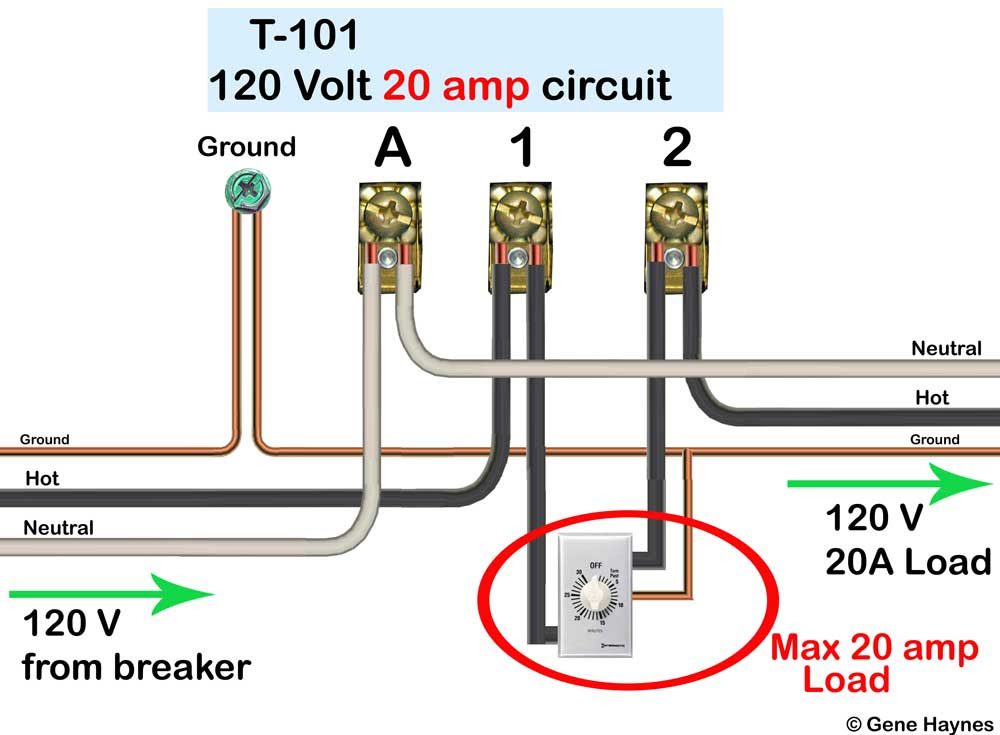
- Wiring Configuration: The diagram outlines the specific wire connections required to correctly connect the timer to the electrical system, including the power supply, load, and any additional control devices.
- Compatibility: The diagram specifies the compatibility of the timer with different electrical systems and loads, such as incandescent, fluorescent, or LED lighting.
- Programming Instructions: The diagram provides step-by-step instructions on how to program the timer’s time settings and operating modes.
- Troubleshooting Tips: The diagram may include troubleshooting tips to help identify and resolve common wiring or programming issues.
- Safety Precautions: The diagram emphasizes the importance of following proper safety precautions during installation and maintenance, such as turning off the power supply before working on the timer.
Detailed discussion on the key aspects, through examples, connections, or linkage to the main topic: The Intermatic T101 Timer Wiring Diagram serves as a valuable resource for ensuring the proper functionality and longevity of the in-wall timer. Its detailed instructions and safety precautions help prevent electrical hazards and ensure reliable operation. By carefully following the diagram’s guidelines, users can effectively control lighting or other electrical devices based on their desired schedules, leading to energy savings, increased convenience, and enhanced security.
Wiring Configuration
The Intermatic T101 Timer Wiring Diagram provides detailed instructions on the specific wire connections necessary to correctly install and wire the timer. These instructions are crucial for ensuring the safe and proper operation of the device. Without a proper wiring configuration, the timer may not function correctly or could pose electrical hazards.
The wiring configuration outlined in the diagram typically includes the following connections:
- Connection to the power supply: The timer must be connected to a power source to receive electricity and operate.
- Connection to the load: The timer controls the flow of electricity to the load, which can be a light fixture, appliance, or other electrical device.
- Connection to any additional control devices: In some cases, the timer may be used in conjunction with other control devices, such as motion sensors or photocells. The wiring diagram will provide instructions on how to connect these additional devices.
Understanding the wiring configuration of the Intermatic T101 Timer Wiring Diagram is essential for ensuring the proper installation and operation of the timer. By following the instructions outlined in the diagram, users can prevent electrical hazards, ensure reliable operation, and optimize the energy-saving and convenience benefits of the timer.
Compatibility
Within the context of the Intermatic T101 Timer Wiring Diagram, compatibility plays a crucial role in ensuring the safe and effective operation of the timer. The diagram specifies the compatibility of the timer with different electrical systems and loads, ensuring that it can be used in a wide range of applications.
- Electrical Systems: The wiring diagram specifies the compatibility of the timer with different electrical systems, such as 120V AC or 240V AC. This information is essential to ensure that the timer is connected to the correct voltage and frequency for the electrical system in which it is being used.
- Load Types: The wiring diagram also specifies the compatibility of the timer with different types of loads, such as incandescent, fluorescent, or LED lighting. This information is important to ensure that the timer is capable of handling the electrical load of the devices it is controlling.
- Wattage and Amperage: The wiring diagram may also specify the maximum wattage or amperage that the timer can handle. This information is important to ensure that the timer is not overloaded and can safely control the load.
- Special Features: The wiring diagram may also specify any special features or considerations related to compatibility. For example, some timers may be compatible with dimmable loads or may require the use of a contactor for high-wattage loads.
Understanding the compatibility specifications outlined in the Intermatic T101 Timer Wiring Diagram is essential for ensuring the proper installation and operation of the timer. By carefully following the diagram’s instructions, users can avoid electrical hazards, ensure reliable operation, and optimize the energy-saving and convenience benefits of the timer.
Programming Instructions
Within the context of “Intermatic T101 Timer Wiring Diagram”, understanding the programming instructions is crucial for harnessing the full functionality of the timer. The diagram provides detailed, step-by-step guidance on how to program the timer’s time settings and operating modes, ensuring optimal performance and energy efficiency.
-
Time Setting:
The diagram outlines how to set the timer’s clock and program specific time intervals for turning devices on or off. This allows for precise control over lighting schedules, appliance operation, and other automated tasks. -
Operating Modes:
The diagram explains how to select and configure various operating modes, such as daily, weekly, or weekend modes. These modes enable flexible scheduling options to meet different user needs and preferences. -
Special Features:
The diagram may include instructions on how to utilize special features of the timer, such as random vacation mode or sunrise/sunset settings. These features enhance convenience and provide additional customization options. -
Troubleshooting:
The diagram may also provide troubleshooting tips related to programming issues. This helps users identify and resolve common problems, ensuring seamless operation of the timer.
By carefully following the programming instructions outlined in the “Intermatic T101 Timer Wiring Diagram”, users can effectively automate lighting, appliances, and other electrical devices, maximizing energy savings, convenience, and security. The detailed guidance provided in the diagram empowers users to fully utilize the timer’s capabilities and customize it to meet their specific needs.
Troubleshooting Tips
Within the context of “Intermatic T101 Timer Wiring Diagram”, troubleshooting tips are invaluable aids for addressing common issues related to wiring and programming. The diagram may provide a range of specific troubleshooting tips to assist users in identifying and resolving these issues, ensuring smooth operation of the timer.
-
Identifying Wiring Faults:
Troubleshooting tips may guide users in checking for loose connections, incorrect wire sizing, or faulty wiring components. By providing step-by-step instructions, the diagram helps users pinpoint and rectify wiring faults, preventing potential electrical hazards. -
Resolving Programming Errors:
The diagram may offer guidance on resolving common programming errors, such as incorrect time settings or misconfigured operating modes. Troubleshooting tips can help users navigate the timer’s programming interface and ensure that the desired schedules and settings are implemented accurately.
These troubleshooting tips empower users to independently address minor issues with the Intermatic T101 Timer, avoiding the need for professional assistance in many cases. By providing clear and concise instructions, the diagram enhances the overall user experience and ensures that the timer operates reliably and efficiently.
Safety Precautions
Within the context of the “Intermatic T101 Timer Wiring Diagram”, safety precautions are of paramount importance, ensuring the safe installation, maintenance, and operation of the timer. The diagram emphasizes the critical step of turning off the power supply before working on the timer, as it directly affects the safety of individuals performing the task and the integrity of the electrical system.
The consequences of neglecting safety precautions, such as failing to turn off the power supply, can be severe. Live electrical circuits pose significant risks of electrical shock, burns, or even electrocution. By explicitly highlighting this precaution, the diagram instills a safety-first mindset and helps prevent accidents.
Moreover, adhering to safety precautions outlined in the diagram is not only crucial for personal safety but also for the longevity of the timer and the electrical system. Improper handling or incorrect wiring practices can damage the timer, void warranties, and potentially lead to electrical faults or fires.
In summary, the safety precautions outlined in the “Intermatic T101 Timer Wiring Diagram” serve as a cornerstone for safe and responsible electrical practices. Understanding and adhering to these precautions empower users to work confidently with the timer, ensuring their well-being and the integrity of the electrical system.


Related Posts


