An Illuminated 5 Pin Rocker Switch Wiring Diagram illustrates the electrical connections and wiring arrangement for a rocker switch with 5 terminals and an integrated LED indicator light. The rocker switch is a mechanical device that controls the flow of electricity through a circuit, typically by toggling between two positions: on and off. The additional 5th terminal allows for the connection of an LED light, which illuminates when the switch is in the “on” position. This provides visual feedback to the user, indicating the switch’s current state.
Illuminated 5 Pin Rocker Switches are commonly used in electronic devices, appliances, and industrial control panels. They offer several benefits, including ease of use, durability, and the ability to provide visual indication of the switch’s status. Historically, rocker switches were simple mechanical devices without lighting, but the addition of an LED indicator significantly improved their functionality and user experience.
The following article will explore the principles of operation, design considerations, practical applications, and selection criteria for Illuminated 5 Pin Rocker Switches. By understanding these aspects, electrical engineers, technicians, and designers can effectively incorporate these components into their projects, ensuring reliable and user-friendly electrical systems.
Identifying the key aspects of an Illuminated 5 Pin Rocker Switch Wiring Diagram is crucial for understanding its functionality, application, and integration. By exploring the essential aspects, electrical engineers, technicians, and designers can effectively utilize these components in their projects.
- Circuit Control: This aspect describes the primary function of the rocker switch, which is to control the flow of electricity in a circuit.
- Switching Mechanism: It refers to the internal mechanism of the switch, allowing it to toggle between “on” and “off” positions.
- LED Indicator: This aspect highlights the presence of an integrated LED light that provides visual indication of the switch’s status.
- Terminal Arrangement: It explains the configuration and purpose of the five terminals on the switch, including power, load, and LED connections.
- Wiring Configuration: This aspect focuses on the electrical connections and wiring scheme for proper switch operation.
- Durability and Reliability: It emphasizes the importance of switch construction and materials, ensuring longevity and resistance to wear and tear.
- Safety Features: This aspect discusses any built-in safety mechanisms, such as insulation or surge protection, to enhance user safety.
- Application Considerations: It explores the various factors to consider when selecting a switch for a specific application, such as load current, voltage rating, and environmental conditions.
- Industry Standards and Certifications: This aspect highlights the importance of adhering to established standards and obtaining necessary certifications to ensure product quality and safety.
These key aspects provide a comprehensive understanding of Illuminated 5 Pin Rocker Switch Wiring Diagrams. By considering these factors, engineers and technicians can make informed decisions when selecting and incorporating these components into their designs, ensuring, usability, and compliance with industry regulations.
Circuit Control
In the context of an Illuminated 5 Pin Rocker Switch Wiring Diagram, Circuit Control is paramount. The rocker switch serves as the central component responsible for regulating the flow of electricity within a circuit, enabling control over electrical devices and systems. This aspect encompasses several key facets, including:
- Power Source Connection: The switch establishes the connection between the power source and the electrical load, facilitating the flow of current when in the “on” position.
- Load Control: The rocker switch directly controls the electrical load, turning it on or off. This allows users to manage the operation of devices, appliances, or lighting systems.
- Circuit Protection: By interrupting the circuit when in the “off” position, the switch protects the electrical system from overloads, short circuits, and other potential hazards.
- Manual Override: Rocker switches provide manual control over electrical circuits, enabling users to override automated systems or make adjustments as needed.
These facets collectively highlight the crucial role of Circuit Control in Illuminated 5 Pin Rocker Switch Wiring Diagrams. The ability to control the flow of electricity is fundamental to the functionality of electrical systems, ensuring safety, efficiency, and user convenience.
Switching Mechanism
The Switching Mechanism is a crucial component of the Illuminated 5 Pin Rocker Switch Wiring Diagram, as it governs the switch’s ability to control the flow of electricity. This mechanism is responsible for establishing and interrupting the electrical connection within the circuit, thereby turning devices or systems on and off.
At its core, the Switching Mechanism consists of movable contacts that physically make or break the electrical connection. When the switch is in the “on” position, these contacts are brought together, allowing current to flow through the circuit. Conversely, in the “off” position, the contacts are separated, blocking the flow of electricity.
In the context of an Illuminated 5 Pin Rocker Switch, the Switching Mechanism is typically designed to handle specific voltage and current ratings. These ratings determine the maximum electrical load that the switch can safely control. The internal contacts are made of conductive materials, such as copper or silver alloys, to ensure reliable and efficient switching.
Understanding the Switching Mechanism is essential for selecting and using Illuminated 5 Pin Rocker Switches effectively. By considering the load requirements, voltage ratings, and durability aspects of the switch, engineers and technicians can ensure that the chosen switch meets the specific demands of their application.
In practical applications, the Switching Mechanism plays a vital role in controlling a wide range of electrical devices and systems. From simple lighting circuits to complex industrial machinery, these switches provide a reliable and user-friendly means of managing electrical power.
LED Indicator
The LED Indicator is a critical component of the Illuminated 5 Pin Rocker Switch Wiring Diagram, as it provides visual feedback to the user, indicating the switch’s current state. This aspect is particularly important in applications where the switch’s position is not immediately apparent, such as in dimly lit environments or when the switch is located in a hard-to-reach area.
The LED Indicator is typically connected to the switch’s terminals via a small resistor, which limits the current flowing through the LED and prevents it from burning out. The resistor value is chosen based on the LED’s voltage and current requirements.
In real-life applications, the LED Indicator is commonly used in various electronic devices, appliances, and industrial control panels. For example, in a home lighting system, an Illuminated 5 Pin Rocker Switch with an LED Indicator can be used to control a light fixture. When the switch is turned on, the LED Indicator illuminates, providing a clear visual indication that the light is on. Similarly, in industrial settings, Illuminated 5 Pin Rocker Switches with LED Indicators are used to control machinery and equipment, providing operators with a quick and easy way to monitor the status of their systems.
Understanding the connection between the LED Indicator and the Illuminated 5 Pin Rocker Switch Wiring Diagram is essential for selecting and using these switches effectively. By considering the voltage and current requirements of the LED, as well as the desired brightness and color, engineers and technicians can choose the appropriate switch for their specific application.
Terminal Arrangement
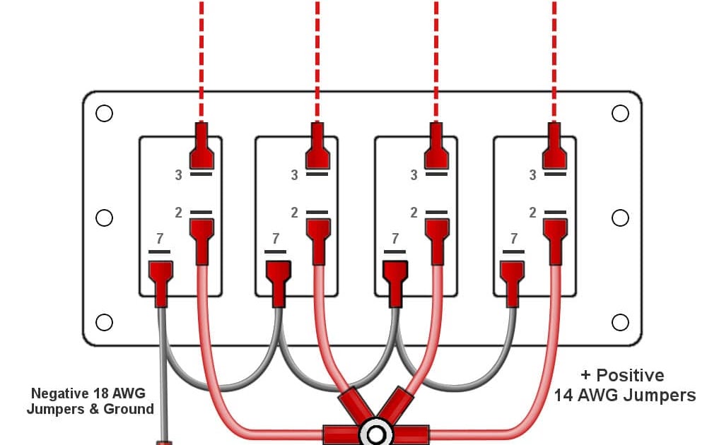
In the context of Illuminated 5 Pin Rocker Switch Wiring Diagrams, Terminal Arrangement holds significant importance as it dictates the physical layout and functionality of the switch’s electrical connections. The five terminals serve distinct purposes in controlling the flow of electricity, providing visual feedback, and ensuring safe and reliable operation.
- Power Terminals: These terminals establish the connection between the power source and the switch, allowing electricity to enter and exit the switch.
- Load Terminals: The load terminals connect the switch to the electrical load, such as a light fixture or motor. When the switch is turned on, electricity flows from the power terminals through the switch to the load terminals, powering the connected device.
- LED Terminals: Illuminated 5 Pin Rocker Switches incorporate an LED indicator light, which requires two terminals for its operation: one for the positive connection and one for the negative connection. These terminals allow the LED to illuminate when the switch is turned on.
- Common Terminal: Some Illuminated 5 Pin Rocker Switches have a common terminal, which serves as a reference point for both the power and load terminals. This configuration simplifies the wiring process and reduces the chances of incorrect connections.
Understanding the Terminal Arrangement of Illuminated 5 Pin Rocker Switches is crucial for proper installation and operation. By carefully following the wiring diagram and connecting the terminals correctly, electrical professionals can ensure that the switch functions as intended, providing reliable control over electrical devices and systems.
Wiring Configuration
Within the context of Illuminated 5 Pin Rocker Switch Wiring Diagrams, Wiring Configuration plays a critical role in ensuring the switch’s functionality, safety, and reliability. The wiring scheme dictates how the switch’s terminals are connected to the power source, load, and LED indicator, allowing the switch to control the flow of electricity effectively.
The importance of Wiring Configuration stems from the fact that incorrect wiring can lead to malfunctions, electrical hazards, and even damage to the switch or connected devices. By adhering to the specified wiring diagram, electrical professionals can ensure that the switch is connected properly, minimizing the risk of electrical issues and ensuring optimal performance.
In real-life applications, Wiring Configuration is a crucial aspect of various electrical installations, including home lighting systems, industrial control panels, and automotive electrical systems. For instance, in a home lighting system, the Wiring Configuration of an Illuminated 5 Pin Rocker Switch determines how the switch controls the flow of electricity to a light fixture. Proper wiring ensures that the light turns on and off as intended, providing convenient and safe control of lighting.
Understanding Wiring Configuration empowers electrical professionals to design, install, and troubleshoot electrical systems with confidence. By mastering the principles of switch wiring, they can ensure that electrical devices and systems operate reliably, efficiently, and in accordance with safety standards.
Durability and Reliability
Within the context of Illuminated 5 Pin Rocker Switch Wiring Diagrams, Durability and Reliability are of paramount importance, as they directly impact the switch’s performance, lifespan, and safety. The construction and materials used in the switch determine its ability to withstand harsh conditions, resist wear and tear, and operate consistently over extended periods.
A durable and reliable Illuminated 5 Pin Rocker Switch ensures accurate and dependable control of electrical circuits. The switch’s construction, including the choice of materials for its housing, contacts, and terminals, plays a crucial role in its ability to handle electrical loads, withstand environmental factors, and resist corrosion.
For example, in industrial settings where switches are subjected to frequent use, vibrations, and exposure to dust and moisture, a robust and durable Illuminated 5 Pin Rocker Switch is essential for maintaining reliable operation and preventing downtime. The switch’s housing should provide adequate protection against physical impact and environmental hazards, while the contacts should be made of high-quality conductive materials to ensure low resistance and minimal voltage drop.
Understanding the connection between Durability and Reliability and Illuminated 5 Pin Rocker Switch Wiring Diagrams empowers electrical professionals to select and install switches that meet the specific demands of their applications. By considering factors such as the operating environment, expected usage patterns, and required safety standards, they can choose switches that provide long-lasting performance, minimizing the risk of switch failure and ensuring the safety and reliability of electrical systems.
Safety Features
Within the context of Illuminated 5 Pin Rocker Switch Wiring Diagrams, Safety Features play a critical role in ensuring the safe and reliable operation of electrical systems. These features are designed to protect users from electrical hazards, such as electric shock, short circuits, and overloads, which can cause injury or damage to equipment.
One of the most important Safety Features is insulation. Insulation is a non-conductive material that surrounds the switch’s electrical components, preventing accidental contact with live parts. This helps to protect users from electric shock and prevents short circuits, which can occur when live parts come into contact with each other.
Another important Safety Feature is surge protection. Surge protection devices are designed to divert excess voltage away from the switch and its connected devices, protecting them from damage caused by power surges. This is particularly important in areas where power surges are common, such as during thunderstorms or when large electrical devices are turned on or off.
Understanding the connection between Safety Features and Illuminated 5 Pin Rocker Switch Wiring Diagrams is essential for electrical professionals. By incorporating appropriate safety features into their designs, they can help to ensure the safe and reliable operation of electrical systems, minimizing the risk of accidents and equipment damage.
Application Considerations
In the context of Illuminated 5 Pin Rocker Switch Wiring Diagrams, Application Considerations play a crucial role in ensuring that the chosen switch meets the specific requirements and demands of the intended application. Several key factors must be taken into account to select an appropriate switch that will perform reliably and safely.
- Load Current: The load current is the amount of electrical current that the switch will be required to handle. It is important to select a switch that is rated for a current equal to or greater than the load current to prevent overheating and potential damage to the switch.
- Voltage Rating: The voltage rating of the switch must be equal to or greater than the voltage of the circuit in which it will be used. Using a switch with a voltage rating below the circuit voltage can lead to arcing, overheating, and switch failure.
- Environmental Conditions: The environmental conditions in which the switch will be used must be considered. Factors such as temperature, humidity, and exposure to dust or moisture can affect the switch’s performance and durability. It is important to select a switch that is designed to withstand the expected environmental conditions.
- Special Features: Some applications may require switches with additional features, such as , momentary action, or multiple poles. These special features can enhance the functionality and ease of use of the switch in specific applications.
By carefully considering these Application Considerations, electrical professionals can select Illuminated 5 Pin Rocker Switches that are optimally suited for their intended applications. This ensures reliable and safe operation, prevents premature switch failure, and meets the specific requirements of the electrical system.
Industry Standards and Certifications
Within the context of Illuminated 5 Pin Rocker Switch Wiring Diagrams, Industry Standards and Certifications play a critical role in ensuring the reliability, safety, and performance of these components. Adhering to established standards and obtaining necessary certifications provides assurance that switches meet specific quality and safety requirements, giving engineers and users confidence in their proper functioning.
- Compliance with Safety Regulations: Industry standards often incorporate safety regulations and guidelines to minimize the risk of electrical hazards. By meeting these standards, manufacturers can demonstrate that their switches comply with safety requirements, ensuring the well-being of users and preventing potential accidents.
- Quality Assurance: Certifications from accredited organizations provide independent verification that switches meet specific quality criteria. These certifications assess factors such as material durability, switch lifecycle, and electrical performance, giving users assurance of the switch’s reliability and longevity.
- Interoperability and Compatibility: Industry standards promote interoperability and compatibility between switches from different manufacturers. By adhering to these standards, switches can be easily integrated into various electrical systems, simplifying installation and ensuring seamless operation.
- Environmental Considerations: Some industry standards address environmental concerns, such as the use of eco-friendly materials and adherence to energy efficiency guidelines. By meeting these standards, manufacturers demonstrate their commitment to environmental sustainability and contribute to a greener future.
In summary, Industry Standards and Certifications serve as essential benchmarks for Illuminated 5 Pin Rocker Switch Wiring Diagrams, ensuring the safety, reliability, and quality of these components. By adhering to established standards and obtaining necessary certifications, manufacturers can instill confidence in their products and contribute to the overall safety and performance of electrical systems.


Related Posts


