An ignition coil condenser wiring diagram is a schematic representation of the electrical connections between the ignition coil, condenser, and other components of an ignition system. It provides a visual guide for understanding the flow of electricity through the system and ensures proper installation and maintenance.
The ignition coil condenser is a capacitor that stores electrical energy and releases it to create a spark at the spark plug. By reducing arcing across the ignition points and prolonging the spark duration, the condenser improves engine performance, fuel efficiency, and lowers emissions.
The development of the ignition coil condenser in the early 20th century revolutionized ignition systems, leading to more efficient and reliable internal combustion engines. Today, ignition coil condensers are essential components in a wide range of vehicles and industrial engines.
Ignition coil condenser wiring diagrams are essential for understanding, troubleshooting, and maintaining ignition systems. They provide a visual representation of the electrical connections between the ignition coil, condenser, and other components, ensuring proper installation and operation.
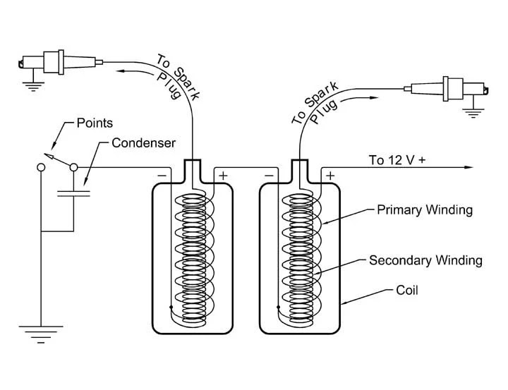
- Circuitry: The diagram shows the complete electrical circuit, including the ignition coil, condenser, spark plugs, and any other relevant components.
- Connections: The diagram clearly indicates how the components are connected to each other, including the polarity of the connections.
- Grounding: The diagram shows how the components are grounded, which is important for proper electrical flow and to prevent electrical interference.
- Component Identification: The diagram can help identify the different components in the ignition system, which is useful for troubleshooting and repair.
- Troubleshooting: The diagram can help troubleshoot ignition problems by providing a visual representation of the electrical flow.
- Maintenance: The diagram can help with maintenance tasks, such as replacing the ignition coil or condenser, by providing a clear understanding of how the components are connected.
- Performance Optimization: The diagram can help optimize ignition performance by showing how to adjust the timing and other parameters.
- Safety: The diagram can help ensure safe operation of the ignition system by providing information about potential electrical hazards.
- Compatibility: The diagram can help ensure compatibility between different ignition system components, such as the ignition coil and condenser.
In conclusion, ignition coil condenser wiring diagrams are valuable tools for understanding, maintaining, and troubleshooting ignition systems. They provide a visual representation of the electrical connections, helping to ensure proper installation, operation, and performance.
Circuitry: The diagram shows the complete electrical circuit, including the ignition coil, condenser, spark plugs, and any other relevant components.
Ignition coil condenser wiring diagrams provide a visual representation of the complete electrical circuit, including the ignition coil, condenser, spark plugs, and any other relevant components. This allows for a clear understanding of how electricity flows through the ignition system, ensuring proper installation, operation, and performance.
- Components of the Circuit: Ignition coil condenser wiring diagrams show the different components of the ignition circuit, including the ignition coil, condenser, spark plugs, distributor (in older vehicles), ignition switch, and battery.
- Electrical Connections: The diagram shows how the components are electrically connected to each other. This includes the polarity of the connections, which is important for proper operation.
- Grounding: The diagram shows how the components are grounded. Proper grounding is essential for electrical safety and to prevent electrical interference.
- Circuit Analysis: The diagram can be used to analyze the electrical circuit, troubleshoot problems, and optimize performance.
Overall, the circuitry aspect of ignition coil condenser wiring diagrams is crucial for understanding, maintaining, and troubleshooting ignition systems. It provides a visual representation of the electrical connections, helping to ensure proper operation and performance.
Connections: The diagram clearly indicates how the components are connected to each other, including the polarity of the connections.
Ignition coil condenser wiring diagrams provide clear indications of how the components are connected to each other, including the polarity of the connections. This information is vital for proper installation, operation, and troubleshooting of ignition systems.
- Component Identification: The diagram helps identify the different components in the ignition system, such as the ignition coil, condenser, spark plugs, and distributor (in older vehicles).
- Polarity: The diagram indicates the polarity of the connections, which is important for proper operation. Incorrect polarity can damage components or prevent the system from functioning correctly.
- Grounding: The diagram shows how the components are grounded. Proper grounding is essential for electrical safety and to prevent electrical interference.
- Troubleshooting: The diagram can help troubleshoot ignition problems by providing a visual representation of the electrical connections. This can help identify loose or disconnected wires, shorts, or other issues.
Overall, the “Connections” aspect of ignition coil condenser wiring diagrams is crucial for understanding, maintaining, and troubleshooting ignition systems. It provides a clear visual representation of how the components are connected, ensuring proper operation and performance.
Grounding: The diagram shows how the components are grounded, which is important for proper electrical flow and to prevent electrical interference.
Grounding is a critical component of ignition coil condenser wiring diagrams because it ensures that the electrical current has a complete circuit path. Without proper grounding, the electrical current can become erratic and cause problems with the ignition system.
In an ignition coil condenser wiring diagram, the components are grounded to the chassis of the vehicle. This provides a low-resistance path for the electrical current to flow back to the battery. The grounding also helps to prevent electrical interference from other components in the vehicle.
Real-life examples of grounding in ignition coil condenser wiring diagrams include the connection of the ignition coil to the engine block and the connection of the condenser to the distributor housing. These connections provide a solid ground for the electrical current to flow through.
The practical applications of understanding grounding in ignition coil condenser wiring diagrams include the ability to troubleshoot ignition problems. If there is a problem with the grounding, it can cause the ignition system to malfunction. By understanding how the components are grounded, it is possible to identify and fix the problem.
In summary, grounding is a critical component of ignition coil condenser wiring diagrams because it ensures that the electrical current has a complete circuit path. Without proper grounding, the ignition system can malfunction. Understanding grounding is important for troubleshooting ignition problems and maintaining the proper operation of the ignition system.
Component Identification: The diagram can help identify the different components in the ignition system, which is useful for troubleshooting and repair.
Identifying the components of an ignition coil condenser wiring diagram is crucial for troubleshooting and repairing ignition systems. The diagram provides a visual representation of the components and their connections, making it easier to locate and diagnose problems.
- Ignition Coil: The ignition coil is a transformer that converts the vehicle’s low-voltage electrical current into a high-voltage current. The high-voltage current is then sent to the spark plugs to create a spark that ignites the air-fuel mixture in the engine’s cylinders.
- Condenser: The condenser is a capacitor that stores electrical energy and releases it to the ignition coil. This helps to create a stronger spark and improve engine performance.
- Spark Plugs: The spark plugs are responsible for creating the spark that ignites the air-fuel mixture in the engine’s cylinders.
- Distributor (in older vehicles): The distributor is a mechanical device that distributes the high-voltage current from the ignition coil to the spark plugs.
Being able to identify the different components in an ignition coil condenser wiring diagram is essential for troubleshooting and repairing ignition systems. By understanding the function of each component and how it connects to the other components, it is possible to quickly and accurately diagnose problems and make the necessary repairs.
Troubleshooting: The diagram can help troubleshoot ignition problems by providing a visual representation of the electrical flow.
Ignition coil condenser wiring diagrams are essential for troubleshooting ignition problems because they provide a visual representation of the electrical flow. This allows technicians to quickly identify and diagnose problems with the ignition system.
- Identifying Faulty Components: The diagram can help identify faulty components in the ignition system. By understanding the electrical flow, technicians can isolate the problem to a specific component, such as the ignition coil, condenser, or spark plugs.
- Tracing Electrical Connections: The diagram can help trace electrical connections to identify loose or disconnected wires. This is important because loose or disconnected wires can cause intermittent ignition problems that can be difficult to diagnose.
- Analyzing Electrical Flow: The diagram can help analyze the electrical flow to identify problems with the timing or duration of the spark. This is important because the timing and duration of the spark are critical for engine performance.
- Testing Components: The diagram can help test components in the ignition system. By understanding the electrical flow, technicians can test components such as the ignition coil and condenser to ensure that they are functioning properly.
Troubleshooting ignition problems using ignition coil condenser wiring diagrams requires a good understanding of the ignition system and the electrical flow. However, the visual representation provided by the diagram makes it a valuable tool for diagnosing and repairing ignition problems.
Maintenance: The diagram can help with maintenance tasks, such as replacing the ignition coil or condenser, by providing a clear understanding of how the components are connected.
Ignition coil condenser wiring diagrams play a critical role in maintenance tasks, particularly when replacing the ignition coil or condenser. These diagrams provide a clear visual representation of the electrical connections between the ignition coil, condenser, and other components within the ignition system. By understanding these connections, mechanics can efficiently and accurately replace faulty components, ensuring optimal performance and longevity of the ignition system.
Real-life examples of the importance of ignition coil condenser wiring diagrams in maintenance include:
Replacing the ignition coil: The diagram guides the mechanic in identifying the correct connections for the new ignition coil, ensuring proper polarity and avoiding damage to the electrical system. Replacing the condenser: The diagram helps locate the condenser and provides instructions on how to disconnect and replace it, minimizing the risk of electrical shock or damage to the ignition system components.
Understanding ignition coil condenser wiring diagrams enables mechanics to perform maintenance tasks with greater confidence and accuracy, ultimately contributing to the reliable operation of the vehicle’s ignition system.
Performance Optimization: The diagram can help optimize ignition performance by showing how to adjust the timing and other parameters.
Ignition coil condenser wiring diagrams are critical for optimizing ignition performance because they provide a visual representation of how to adjust the timing and other parameters that affect ignition performance. By understanding these parameters and how to adjust them, mechanics can fine-tune the ignition system to improve engine performance, fuel efficiency, and emissions.
Real-life examples of performance optimization using ignition coil condenser wiring diagrams include:
Adjusting ignition timing: The diagram shows how to adjust the timing of the spark to optimize engine performance. Adjusting the timing can improve engine power, torque, and fuel efficiency. Adjusting dwell time: The diagram shows how to adjust the dwell time of the ignition coil. Dwell time is the amount of time that the ignition coil is energized. Adjusting the dwell time can improve spark duration and ignition performance.
Understanding ignition coil condenser wiring diagrams enables mechanics to optimize ignition performance by fine-tuning the timing and other parameters. This can lead to improved engine performance, fuel efficiency, and emissions.
Safety: The diagram can help ensure safe operation of the ignition system by providing information about potential electrical hazards.
Ignition coil condenser wiring diagrams play a crucial role in ensuring the safe operation of the ignition system by providing information about potential electrical hazards. These diagrams help identify potential risks and guide proper handling and maintenance procedures to prevent electrical accidents or damage to the ignition system components.
Real-life examples of how ignition coil condenser wiring diagrams contribute to safety include:
Identifying high-voltage components: The diagram clearly marks high-voltage components, such as the ignition coil and spark plugs, alerting technicians to the potential for electrical shock and the need for proper insulation and precautions. Grounding instructions: The diagram provides instructions on how to properly ground the ignition system components. Proper grounding prevents electrical current from flowing through unintended paths, reducing the risk of electrical fires or damage to the vehicle’s electrical system.
Understanding ignition coil condenser wiring diagrams enables technicians to perform maintenance and repairs safely and effectively, minimizing the risk of electrical hazards and ensuring the proper functioning of the ignition system.
Compatibility: The diagram can help ensure compatibility between different ignition system components, such as the ignition coil and condenser.
Ignition coil condenser wiring diagrams play a critical role in ensuring compatibility between different ignition system components, such as the ignition coil and condenser. These diagrams provide the necessary information to match and connect components with different specifications and characteristics, ensuring optimal performance and preventing damage to the ignition system.
Real-life examples of the importance of compatibility in ignition coil condenser wiring diagrams include:
Upgrading ignition components: When upgrading or replacing ignition components, the diagram helps ensure that the new components are compatible with the existing ignition system. This is especially important when changing the ignition coil or condenser, as these components must be matched to the specific requirements of the engine. Troubleshooting compatibility issues: If an ignition system is experiencing problems, the diagram can help identify compatibility issues between components. For instance, if the ignition coil and condenser are not compatible, it can lead to weak spark or ignition failure.
Understanding ignition coil condenser wiring diagrams allows technicians and enthusiasts to select and install compatible ignition components, ensuring a properly functioning and efficient ignition system. By addressing compatibility, these diagrams contribute to the overall reliability and performance of the vehicle’s ignition system.
![[DIAGRAM] 12 Volt Auto Coil Wiring Diagrams](https://i0.wp.com/img1.tongtool.com/u/535587bc3756d25b369e7a9b5ba7dec5ca74oulx.jpg?w=665&ssl=1)


Related Posts


