A Hunter Fan Remote Wiring Diagram outlines the electrical connections between a Hunter ceiling fan, its remote control, and a household’s electrical system. This circuitry allows for wireless control of the fan’s speed and illumination settings.
Wiring diagrams are crucial for ensuring a safe and functional fan installation. They guide electricians and homeowners alike in correctly connecting wires and avoiding potential hazards such as electrical fires. Moreover, these diagrams enhance the overall convenience of operating the fan remotely, eliminating the need for manual adjustments.
Historically, ceiling fans were controlled with pull cords or wall switches. The introduction of remote control technology revolutionized fan operation, providing users with greater flexibility and ease of use. Today, these diagrams remain indispensable for harnessing the full benefits of wireless fan control.
Understanding the essential aspects of a Hunter Fan Remote Wiring Diagram is paramount for a safe and efficient fan installation. Here are nine key aspects to consider:
- Compatibility: Ensuring compatibility between the fan, remote control, and wiring system.
- Electrical Safety: Adhering to electrical codes and regulations for proper wiring practices.
- Circuit Identification: Identifying the correct electrical circuit to power the fan.
- Wire Connections: Understanding the proper techniques for connecting wires to the fan, remote receiver, and electrical system.
- Remote Control Pairing: Establishing a stable connection between the remote control and the fan’s receiver.
- Troubleshooting: Identifying and resolving common wiring issues that may arise during installation.
- Maintenance: Understanding the ongoing maintenance requirements to ensure the fan’s longevity.
- Safety Precautions: Implementing safety measures to prevent electrical hazards during installation and operation.
- User Convenience: Enhancing the convenience of operating the fan remotely through the use of a wireless remote control.
These aspects are interconnected and play a crucial role in the successful installation and operation of a Hunter Fan Remote Wiring Diagram. It is essential to have a thorough understanding of these aspects to ensure a safe, functional, and convenient fan system.
Compatibility: Ensuring compatibility between the fan, remote control, and wiring system.
Within the context of “Hunter Fan Remote Wiring Diagram”, ensuring compatibility between the fan, remote control, and wiring system is of paramount importance. This compatibility encompasses various facets, each playing a crucial role in the successful installation and operation of the fan system.
- Fan and Remote Control Pairing: The fan and remote control must be compatible with each other to enable wireless communication and control. This involves matching the operating frequencies and protocols used by both devices.
- Receiver Compatibility: The receiver, which is typically installed on the fan, must be compatible with both the remote control and the fan itself. It acts as the intermediary between the remote control and the fan, receiving and executing commands.
- Electrical System Compatibility: The wiring system of the house must be compatible with the electrical requirements of the fan. This includes ensuring that the circuit can handle the fan’s power consumption and that the wiring is of the correct gauge and type.
- Compliance with Standards: All components of the Hunter Fan Remote Wiring Diagram, including the fan, remote control, receiver, and wiring, should comply with relevant electrical standards and codes. This ensures the safety and reliability of the entire system.
By ensuring compatibility between these components, a Hunter Fan Remote Wiring Diagram can achieve seamless communication, reliable operation, and adherence to safety regulations. Overlooking compatibility issues can result in malfunctioning fans, communication errors, electrical hazards, and code violations.
Electrical Safety: Adhering to electrical codes and regulations for proper wiring practices.
Electrical safety is paramount when it comes to Hunter Fan Remote Wiring Diagrams. Adhering to electrical codes and regulations during the installation process helps to prevent electrical hazards, ensuring the safe operation of the fan. These codes and regulations provide guidelines for proper wiring practices, ensuring that the electrical system is installed correctly and meets safety standards.
One critical aspect of electrical safety is ensuring that the wiring is of the correct gauge and type for the fan’s electrical requirements. Using undersized wiring can lead to overheating and potential fire hazards. Similarly, using the wrong type of wiring can compromise the integrity of the electrical system and increase the risk of electrical shock.
Proper grounding is another crucial aspect of electrical safety. The grounding wire provides a safe path for electrical current to flow in case of a fault, preventing electrocution. Hunter Fan Remote Wiring Diagrams must incorporate proper grounding techniques to ensure the safety of users.
By following electrical codes and regulations, homeowners and electricians can ensure that Hunter Fan Remote Wiring Diagrams are installed safely and in accordance with industry standards. This helps to prevent electrical hazards, protect property, and ensure the well-being of individuals.
Circuit Identification: Identifying the correct electrical circuit to power the fan.
Within the context of “Hunter Fan Remote Wiring Diagram”, circuit identification plays an essential role in ensuring the safe and proper operation of the fan. Identifying the correct electrical circuit involves determining which circuit in the house’s electrical system will provide the necessary power and compatibility for the fan.
- Circuit Capacity: Evaluating whether the circuit can handle the electrical load of the fan. This involves considering the fan’s power consumption and the other electrical devices connected to the same circuit.
- Circuit Compatibility: Determining whether the circuit is compatible with the fan’s electrical requirements. This includes ensuring that the circuit is of the correct voltage and that it can support the type of electrical connection required by the fan.
- Circuit Accessibility: Locating a circuit that is easily accessible for connecting the fan. This involves identifying a circuit that has a junction box or outlet in a convenient location for wiring the fan.
- Circuit Safety: Selecting a circuit that meets electrical safety codes and standards. This involves ensuring that the circuit is properly grounded and protected by circuit breakers or fuses.
Proper circuit identification is crucial for ensuring that the Hunter Fan Remote Wiring Diagram is installed safely and operates efficiently. Overlooking circuit identification can lead to electrical hazards, such as overloading, short circuits, or electrical fires. Therefore, it is essential to carefully consider the circuit capacity, compatibility, accessibility, and safety when identifying the correct electrical circuit to power the fan.
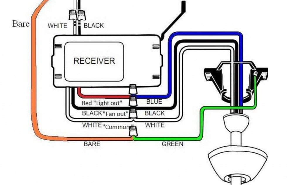
Wire Connections: Understanding the proper techniques for connecting wires to the fan, remote receiver, and electrical system.
Within the context of “Hunter Fan Remote Wiring Diagram”, wire connections are a critical component that ensures the proper functioning and safety of the fan system. Understanding the correct techniques for connecting wires to the fan, remote receiver, and electrical system is essential for a successful installation.
The Hunter Fan Remote Wiring Diagram provides a roadmap for connecting the wires in a specific sequence and configuration. Each wire has a designated function, such as supplying power to the fan, controlling the fan’s speed, or enabling communication between the remote control and the receiver. Improper wire connections can lead to malfunctions, electrical hazards, or even fires.
For instance, if the wires connecting the fan to the power source are not properly secured, it can result in loose connections, arcing, and potential electrical fires. Similarly, incorrect connections between the remote receiver and the fan can disrupt communication, rendering the remote control ineffective.
Therefore, it is crucial to follow the Hunter Fan Remote Wiring Diagram carefully and adhere to proper wire connection techniques. This involves using the correct wire gauge, ensuring secure connections, and employing appropriate connectors and terminals. By understanding and implementing proper wire connections, individuals can ensure the safe and efficient operation of their Hunter Fan Remote Wiring System.
Remote Control Pairing: Establishing a stable connection between the remote control and the fan’s receiver.
Within the context of “Hunter Fan Remote Wiring Diagram”, remote control pairing is a crucial step that ensures seamless communication between the remote control and the fan’s receiver. A stable connection between these two components is essential for effective wireless control of the fan’s functions, such as speed adjustment, oscillation, and illumination.
- Frequency Matching: The remote control and the receiver must be set to the same frequency to communicate effectively. Mismatched frequencies will result in the remote control being unable to send commands to the fan.
- Signal Strength: The strength of the signal transmitted by the remote control should be sufficient to reach the receiver. Obstructions, such as walls or furniture, can weaken the signal and affect the pairing process.
- Pairing Procedure: Different Hunter fan models may have specific pairing procedures. Following the manufacturer’s instructions carefully is essential to establish a successful connection.
- Receiver Compatibility: The receiver should be compatible with the remote control. Using an incompatible receiver will prevent proper communication and control of the fan.
Establishing a stable remote control pairing is crucial for the optimal functioning of the Hunter Fan Remote Wiring System. It ensures that the remote control can reliably transmit commands to the fan, allowing for convenient and effortless control of the fan’s settings.
Troubleshooting: Identifying and resolving common wiring issues that may arise during installation.
Within the context of “Hunter Fan Remote Wiring Diagram”, troubleshooting plays a critical role in ensuring the successful installation and operation of the fan system. Troubleshooting involves identifying and resolving common wiring issues that may arise during the installation process, preventing potential malfunctions and ensuring the fan’s proper functioning.
The Hunter Fan Remote Wiring Diagram provides a roadmap for the wiring process, outlining the connections between the fan, remote control, receiver, and electrical system. However, even with careful planning and execution, wiring issues can occur due to various factors such as loose connections, incorrect wire sizing, or electrical faults.
Troubleshooting these wiring issues requires a systematic approach to pinpoint the root cause of the problem. This may involve checking for loose connections, verifying wire continuity, and ensuring proper grounding. By following the logical steps outlined in the troubleshooting section of the Hunter Fan Remote Wiring Diagram, individuals can effectively identify and resolve common wiring issues, ensuring the safe and efficient operation of their fan system.
For instance, if the fan fails to respond to the remote control, troubleshooting steps may involve checking the batteries in the remote, verifying the pairing between the remote and receiver, and inspecting the wiring connections to the receiver. By addressing these potential issues, individuals can restore proper communication and control of the fan.
Troubleshooting is an integral part of the Hunter Fan Remote Wiring Diagram, empowering individuals to identify and resolve common wiring issues that may arise during installation. Understanding the troubleshooting process and applying appropriate corrective measures helps ensure a successful and safe fan installation, enhancing the overall user experience and ensuring the fan’s optimal performance.
Maintenance: Understanding the ongoing maintenance requirements to ensure the fan’s longevity.
Within the context of “Hunter Fan Remote Wiring Diagram”, understanding the ongoing maintenance requirements is crucial for ensuring the fan’s longevity and optimal performance. Regular maintenance helps prevent potential issues, extend the fan’s lifespan, and enhance its overall efficiency.
- Regular Cleaning: Maintaining a clean fan is essential to prevent dust and debris accumulation, which can affect the fan’s operation and air circulation. Cleaning the fan blades, motor housing, and other components regularly helps ensure smooth operation and prolongs the fan’s life.
- Lubrication: Over time, the fan’s moving parts may require lubrication to reduce friction and prevent wear. Regular lubrication of the motor bearings and other moving components helps ensure smooth operation and extends the fan’s lifespan.
- Electrical Inspection: Periodic electrical inspections are recommended to identify any loose connections, damaged wires, or other electrical issues. Addressing these issues promptly helps prevent electrical hazards and ensures the safe operation of the fan.
- Remote Control Battery Replacement: The remote control used to operate the fan requires regular battery replacement to ensure proper communication with the fan’s receiver. Replacing the batteries as needed helps maintain seamless control and prevents interruptions in fan operation.
By incorporating these maintenance practices into their routine, individuals can enhance the longevity and performance of their Hunter Fan Remote Wiring System. Regular cleaning, lubrication, electrical inspections, and remote control battery replacement contribute to the fan’s optimal functioning, preventing potential issues and extending its lifespan.
Safety Precautions: Implementing safety measures to prevent electrical hazards during installation and operation.
Within the context of “Hunter Fan Remote Wiring Diagram”, safety precautions play a pivotal role in ensuring the safe installation and operation of the fan system. Overlooking these precautions can lead to electrical hazards, posing risks to individuals and property. Implementing proper safety measures is essential to mitigate these risks and ensure a safe and reliable fan system.
- Electrical Code Compliance: Adhering to established electrical codes and regulations is paramount. These codes provide guidelines for proper wiring practices, grounding, and circuit protection, ensuring the electrical system meets safety standards and minimizes the risk of electrical fires and shocks.
- Qualified Electrician Involvement: Engaging a qualified electrician for the installation process is highly recommended. Electricians possess the expertise and experience to handle electrical wiring safely, ensuring connections are secure, components are compatible, and the fan is properly grounded.
- Circuit Capacity Assessment: Before connecting the fan to a circuit, it is crucial to assess the circuit’s capacity to handle the fan’s electrical load. Overloading a circuit can lead to overheating, tripped breakers, or even electrical fires.
- Proper Grounding: Establishing a proper grounding system is essential for safety. Grounding provides a safe path for electrical current to flow in case of a fault, preventing electrocution and protecting against electrical shocks.
By implementing these safety precautions, individuals can minimize the risks associated with electrical hazards during the installation and operation of their Hunter Fan Remote Wiring System. Adhering to electrical codes, involving qualified electricians, assessing circuit capacity, and ensuring proper grounding contribute to a safe and reliable fan system, providing peace of mind and enhancing the overall user experience.
User Convenience: Enhancing the convenience of operating the fan remotely through the use of a wireless remote control.
Within the context of “Hunter Fan Remote Wiring Diagram”, the incorporation of a wireless remote control significantly enhances the convenience of operating the fan. This feature eliminates the need for manual adjustments, providing greater flexibility and ease of use in controlling the fan’s settings.
- Effortless Control: The wireless remote control provides effortless control of the fan’s speed, oscillation, and illumination settings from anywhere within the room. This eliminates the inconvenience of having to physically adjust the fan’s settings, making it particularly convenient for individuals with limited mobility or those who prefer to control the fan from the comfort of their couch or bed.
- Accessibility: The remote control’s portability allows users to operate the fan from any location within the effective range of the wireless signal. This freedom of movement enhances accessibility, enabling users to adjust the fan’s settings without interrupting their activities or having to navigate around obstacles.
- Multi-Function Control: Many Hunter Fan Remote Wiring Diagrams incorporate multi-function remote controls that can operate multiple fans simultaneously. This feature is particularly useful in homes or offices with multiple ceiling fans, allowing users to adjust the settings of all fans with a single remote control.
In summary, the incorporation of a wireless remote control in a Hunter Fan Remote Wiring Diagram greatly enhances the convenience and accessibility of fan operation. This user-centric design feature provides effortless control, eliminates the need for manual adjustments, and allows for multi-fan control from the comfort of a remote location, contributing to a more comfortable and convenient indoor environment.


Related Posts


