A Hopkins Trailer Plug Wiring Diagram visually illustrates the electrical connections between the towing vehicle and the trailer’s electrical system. It provides clear instructions on how to connect the wires correctly to ensure proper functioning of the trailer’s lights, brakes, and other electrical components.
Trailer plug wiring diagrams are crucial for safe and reliable trailer operation. They enable the proper functioning of safety features such as tail lights, turn signals, and brake lights, ensuring visibility during nighttime or inclement weather conditions. Moreover, they optimize the performance of other electrical components like interior lighting, charging systems, and brake controllers.
Historically, trailer wiring diagrams were simple schematics drawn by hand. However, with the advent of modern technology, digital diagrams have become readily available online and in various formats, making them easily accessible and comprehensive.
As we delve into this article, we will explore the components, types, and installation procedures of Hopkins Trailer Plug Wiring Diagrams, highlighting their significance in ensuring safe and efficient trailer operation.
Hopkins Trailer Plug Wiring Diagrams are essential for safe and compliant trailer operation, outlining the electrical connections between the towing vehicle and the trailer. Understanding the key aspects of these wiring diagrams is crucial to ensure proper installation and maintenance.
- Components: Trailer plug wiring diagrams illustrate the various components involved in the electrical connection, including the plug, socket, wires, connectors, and terminals.
- Wiring Types: They specify the types of wires used, such as color-coded stranded or solid wires, and their respective functions (e.g., ground, power, lighting).
- Circuit Protection: Diagrams indicate the use of fuses or circuit breakers to protect the electrical system from overloads and short circuits.
- Lighting Functions: They detail the wiring for various lighting functions, including tail lights, brake lights, turn signals, and clearance lights.
- Braking System Integration: Diagrams show the electrical connections for electric or hydraulic brake systems, ensuring proper trailer braking.
- Auxiliary Power: They outline the wiring for providing auxiliary power to the trailer, enabling the use of appliances or charging systems.
- Grounding: Diagrams emphasize the importance of proper grounding to ensure electrical safety and prevent malfunctions.
- Compatibility: They specify the compatibility of the wiring diagram with different vehicle and trailer models, ensuring proper fit and functionality.
- Safety Compliance: Wiring diagrams adhere to industry standards and regulations, ensuring compliance with safety requirements.
- Troubleshooting: Diagrams serve as a valuable tool for troubleshooting electrical issues, aiding in the identification and rectification of faults.
These key aspects collectively contribute to the effective and safe operation of trailers, enabling the proper functioning of lighting, braking systems, and other electrical components. By understanding these aspects, individuals can ensure proper installation, maintenance, and troubleshooting of Hopkins Trailer Plug Wiring Diagrams, promoting road safety and enhancing the overall towing experience.
Components
The components of a Hopkins Trailer Plug Wiring Diagram play a crucial role in establishing a safe and functional electrical connection between the towing vehicle and the trailer. These components work together to ensure proper functioning of the trailer’s lighting, braking systems, and other electrical features.
- Plug and Socket: The plug and socket are the physical connectors that establish the electrical link between the vehicle and the trailer. They come in various configurations, each designed for specific vehicle and trailer models.
- Wires: The wiring harness consists of color-coded wires that carry electrical current from the vehicle to the trailer. Each wire has a specific function, such as providing power to the lights, brakes, or auxiliary systems.
- Connectors: Connectors are used to join wires and extend the wiring harness. They ensure a secure and reliable connection, preventing loose wires and electrical faults.
- Terminals: Terminals are the endpoints of wires that connect to the plug, socket, or other components. They provide a secure and conductive interface for electrical current to flow.
Understanding the components of a Hopkins Trailer Plug Wiring Diagram is essential for proper installation and maintenance. By ensuring that these components are correctly connected and functioning properly, individuals can ensure the safe and reliable operation of their trailers.
Wiring Types
In Hopkins Trailer Plug Wiring Diagrams, the selection of appropriate wiring types is crucial for ensuring reliable and safe electrical connections. Different types of wires are used based on their specific functions and the electrical requirements of the trailer’s components.
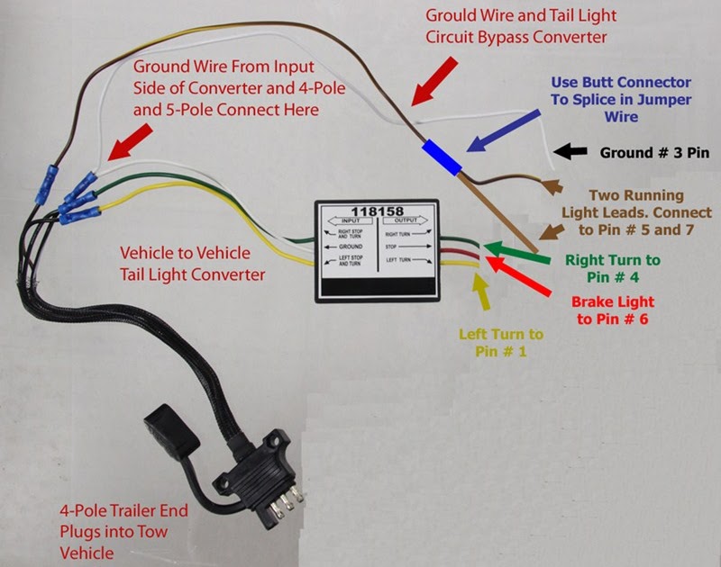
Color-coding: The use of color-coded wires simplifies the identification of each wire’s intended purpose, making the installation and troubleshooting process more efficient. For instance, brown wires typically indicate taillights, while green wires are commonly used for right turn signals.
Stranded vs. Solid Wires: Stranded wires, composed of multiple thin strands, offer greater flexibility and resistance to breakage compared to solid wires. They are often used in areas where movement or vibration is expected, such as the connection between the vehicle and the trailer.
Grounding: Proper grounding is essential for electrical safety and preventing malfunctions. Ground wires provide a path for electrical current to return to its source, ensuring that the trailer’s electrical system functions as intended.
Understanding the different wiring types and their respective functions is critical for the accurate installation and maintenance of Hopkins Trailer Plug Wiring Diagrams. By selecting and using the appropriate wiring types, individuals can ensure the safe and reliable operation of their trailers’ electrical systems.
Circuit Protection
In the context of Hopkins Trailer Plug Wiring Diagrams, circuit protection plays a crucial role in ensuring the safety and reliability of the electrical system. Overloads and short circuits can occur due to various factors, such as faulty wiring, excessive current draw, or accidental contact with metal objects. Without proper circuit protection, these events can lead to damage to the electrical components, electrical fires, or even pose a safety hazard to individuals.
Hopkins Trailer Plug Wiring Diagrams incorporate fuses or circuit breakers to protect the electrical system from such hazards. These devices act as safety switches, interrupting the flow of electrical current when it exceeds a predetermined threshold. By doing so, they prevent damage to sensitive electrical components and reduce the risk of electrical fires.
For instance, if a short circuit occurs in the trailer’s lighting system, the fuse or circuit breaker associated with that circuit will trip, isolating the faulty circuit and preventing damage to other components or the entire electrical system.
Understanding the importance of circuit protection in Hopkins Trailer Plug Wiring Diagrams is essential for ensuring the safe and reliable operation of trailers. By incorporating appropriate fuses or circuit breakers, individuals can minimize the risks associated with electrical faults, protecting their investment and enhancing overall safety.
Lighting Functions
Within the comprehensive framework of Hopkins Trailer Plug Wiring Diagrams, lighting functions hold paramount importance, ensuring the safe and effective operation of trailers during various driving conditions. These diagrams meticulously outline the electrical connections for a range of lighting systems, each serving a distinct purpose in enhancing visibility, safety, and communication on the road.
- Tail Lights: Essential for indicating the presence and position of the trailer, tail lights illuminate the rear of the vehicle, providing clear visibility for other drivers, especially during nighttime or low-visibility conditions.
- Brake Lights: Activated when the brake pedal is depressed, brake lights signal the intention to slow down or stop, alerting following vehicles and preventing potential rear-end collisions.
- Turn Signals: Located on the sides of the trailer, turn signals communicate the driver’s intention to turn or change lanes, ensuring safe maneuvering and reducing the risk of accidents.
- Clearance Lights: Mounted on the highest points of the trailer, clearance lights enhance the visibility of the trailer’s width and height, particularly crucial for larger trailers or those carrying oversized loads.
Collectively, these lighting functions work in harmony to provide a comprehensive lighting system for trailers, ensuring their safe and compliant operation on public roadways. By understanding and adhering to the wiring instructions specified in Hopkins Trailer Plug Wiring Diagrams, individuals can ensure that their trailers are equipped with properly functioning lighting systems, promoting visibility, safety, and compliance with legal requirements.
Braking System Integration
Within the intricate framework of Hopkins Trailer Plug Wiring Diagrams, braking system integration plays a pivotal role in ensuring the safety and functionality of trailers. These diagrams provide detailed instructions for connecting electric or hydraulic brake systems, enabling effective and reliable trailer braking.
- Electrical Components: Wiring diagrams specify the electrical components required for brake system integration, including relays, solenoids, and controllers. These components work in conjunction to transmit electrical signals between the towing vehicle and the trailer’s brake system.
- Brake Light Activation: Diagrams outline the wiring connections for activating the trailer’s brake lights when the towing vehicle’s brake pedal is depressed. This ensures that other drivers are alerted to the trailer’s deceleration, preventing potential rear-end collisions.
- Hydraulic Brake Systems: For trailers equipped with hydraulic brake systems, wiring diagrams provide instructions for connecting the electrical controller to the hydraulic brake actuator. This ensures that electrical signals are converted into hydraulic pressure, actuating the trailer’s brakes.
- Electric Brake Systems: In trailers with electric brake systems, wiring diagrams specify the connections between the electrical controller and the trailer’s electric brakes. These diagrams ensure that the brakes are energized when electrical current is applied, providing effective braking.
By understanding and adhering to the braking system integration instructions provided in Hopkins Trailer Plug Wiring Diagrams, individuals can ensure that their trailers are equipped with properly functioning brake systems. This not only enhances the safety of the trailer and its occupants but also contributes to the overall safety of other vehicles on the road.
Auxiliary Power
Within the comprehensive framework of Hopkins Trailer Plug Wiring Diagrams, auxiliary power plays a crucial role in extending the functionality of trailers beyond basic lighting and braking systems. These diagrams provide detailed instructions for wiring auxiliary power sources, enabling the use of various appliances, charging systems, and other electrical devices on the trailer.
- Power Outlets: Wiring diagrams specify the installation of power outlets within the trailer, allowing users to connect and operate appliances such as refrigerators, microwaves, and power tools.
- Charging Systems: Diagrams outline the wiring for battery charging systems, ensuring that the trailer’s battery remains charged while connected to the towing vehicle or an external power source.
- Electrical Convenience: Auxiliary power wiring enables the installation of interior lighting, fans, and other electrical conveniences, enhancing the comfort and livability of the trailer.
- Safety Features: In some cases, auxiliary power wiring diagrams include instructions for connecting safety features such as security lighting or backup cameras, providing additional peace of mind while towing.
By understanding and adhering to the auxiliary power wiring instructions in Hopkins Trailer Plug Wiring Diagrams, individuals can equip their trailers with the necessary electrical infrastructure to support a wide range of appliances, systems, and safety features. This not only enhances the functionality and convenience of the trailer but also contributes to the overall safety and enjoyment of the towing experience.
Grounding
In the context of Hopkins Trailer Plug Wiring Diagrams, grounding plays a crucial role in establishing a safe and reliable electrical connection between the towing vehicle and the trailer. It serves as a vital component in preventing electrical malfunctions and ensuring the proper functioning of the trailer’s electrical systems.
- Electrical Safety: Proper grounding provides a low-resistance path for electrical current to return to its source, preventing voltage surges and potential electrical shocks.
- Equipment Protection: Grounding helps protect electrical components from damage by providing a safe outlet for excess current, preventing overheating and equipment failure.
- Stable Electrical System: Grounding ensures a stable electrical system by maintaining a consistent voltage level, preventing fluctuations that could disrupt the operation of electrical devices.
- Compliance with Regulations: Grounding practices adhere to electrical safety codes and regulations, ensuring compliance with industry standards and minimizing the risk of electrical hazards.
Understanding the importance of proper grounding and following the guidelines outlined in Hopkins Trailer Plug Wiring Diagrams is essential for ensuring the safe and reliable operation of trailers. By establishing a secure electrical connection and preventing electrical malfunctions, grounding contributes to the overall safety and functionality of the towing system.
Compatibility
Within the realm of Hopkins Trailer Plug Wiring Diagrams, compatibility stands as a cornerstone, ensuring seamless integration between diverse vehicle and trailer models. This critical component plays a pivotal role in establishing a secure and functional electrical connection, safeguarding the integrity of both the towing vehicle and the trailer.
Consider the following real-life example: A meticulous owner meticulously selects a Hopkins Trailer Plug Wiring Diagram compatible with their specific vehicle and trailer combination. By adhering to the specified compatibility guidelines, they can rest assured that the electrical systems of both units will work harmoniously, providing reliable power to the trailer’s lighting, braking, and auxiliary systems.
Understanding the practical significance of compatibility within Hopkins Trailer Plug Wiring Diagrams empowers individuals to make informed decisions when selecting and installing these essential components. It eliminates guesswork and potential compatibility issues, ensuring a safe and worry-free towing experience.
In conclusion, compatibility plays a non-negotiable role in the effective utilization of Hopkins Trailer Plug Wiring Diagrams. By ensuring proper fit and functionality across various vehicle and trailer models, compatibility safeguards the integrity of the electrical connection, promotes optimal performance, and enhances the overall towing experience.
Safety Compliance
The significance of safety compliance within Hopkins Trailer Plug Wiring Diagrams cannot be overstated. These diagrams serve as essential tools in ensuring that trailer electrical systems align with established industry standards and regulations, prioritizing the safety of both the towing vehicle and the trailer itself.
Consider the following real-life example: A Hopkins Trailer Plug Wiring Diagram designed for a specific vehicle and trailer combination meticulously adheres to safety regulations. This ensures that the trailer’s lighting, braking, and auxiliary systems function flawlessly, enhancing visibility, communication, and overall safety on the road. By complying with industry standards, the wiring diagram contributes to the prevention of electrical malfunctions and potential hazards.
Understanding the practical implications of safety compliance empowers individuals to make informed decisions when selecting and installing Hopkins Trailer Plug Wiring Diagrams. This understanding helps prevent electrical fires, system failures, and accidents, safeguarding both the occupants of the towing vehicle and other road users.
In conclusion, safety compliance stands as a cornerstone of Hopkins Trailer Plug Wiring Diagrams. By adhering to industry standards and regulations, these diagrams play a critical role in promoting electrical safety, ensuring reliable trailer operation, and fostering a safer environment on our roadways.
Troubleshooting
Within the realm of Hopkins Trailer Plug Wiring Diagrams, the ability to troubleshoot electrical issues is paramount. These diagrams serve as invaluable tools, providing a systematic approach to identifying and rectifying electrical faults, ensuring the safe and reliable operation of trailers.
The connection between troubleshooting and Hopkins Trailer Plug Wiring Diagrams is evident in the practical applications that arise during the installation and maintenance of trailer electrical systems. Consider the following real-life example: An individual encounters an electrical malfunction in their trailer’s lighting system. By consulting the Hopkins Trailer Plug Wiring Diagram specific to their vehicle and trailer combination, they can systematically trace the electrical connections, identify the source of the fault, and implement the appropriate repairs.
Understanding the practical significance of troubleshooting empowers individuals to address electrical issues with confidence. It enables them to pinpoint the root cause of malfunctions, rather than resorting to guesswork or trial-and-error methods. This not only saves time and effort but also enhances the safety and reliability of the trailer’s electrical system.
In conclusion, troubleshooting is an integral component of Hopkins Trailer Plug Wiring Diagrams. By providing clear instructions and a systematic approach to electrical fault identification and rectification, these diagrams empower individuals to maintain and repair their trailer’s electrical systems effectively. This understanding promotes electrical safety, ensures reliable trailer operation, and contributes to a more enjoyable and worry-free towing experience.


Related Posts


