A Honeywell T9 Wiring Diagram provides a detailed visual guide for connecting the wires of a Honeywell T9 programmable thermostat to its respective terminal blocks. It illustrates the relationship between the thermostat’s labeled terminals and the wires that carry electrical signals to and from connected devices, ensuring proper installation and functionality.
By following the Honeywell T9 Wiring Diagram, technicians can avoid wiring errors, such as incorrect polarity or loose connections, that could compromise the system’s accuracy, reliability, and safety. It facilitates efficient troubleshooting by enabling quick identification of wiring-related issues and enables customization of the thermostat’s settings to meet the unique requirements of specific heating, ventilation, and air conditioning (HVAC) systems.
This article will delve deeper into the complexities of the Honeywell T9 Wiring Diagram, including its various terminal designations, wire gauge recommendations, compatibility with different HVAC equipment, and advanced features such as zone control and remote access. By providing a comprehensive understanding of the diagram’s principles, the article aims to empower HVAC professionals with the knowledge and skills necessary for effective installation, maintenance, and troubleshooting of Honeywell T9 programmable thermostats.
The term “Honeywell T9 Wiring Diagram” is a noun phrase that describes a specific type of technical document used in the installation and maintenance of Honeywell T9 programmable thermostats. As a noun, it plays a pivotal role in conveying essential information about the wiring configurations and electrical connections required for the proper functioning of these thermostats.
- Terminal Designations: Identifies the specific terminals on the thermostat where wires should be connected.
- Wire Gauge Recommendations: Specifies the appropriate wire size for each terminal, ensuring optimal current flow.
- Compatibility: Outlines the thermostat’s compatibility with different types of HVAC equipment, such as furnaces, heat pumps, and air conditioners.
- Zone Control: Explains how to configure the thermostat for controlling multiple heating or cooling zones.
- Remote Access: Describes the features and requirements for accessing and controlling the thermostat remotely.
- Advanced Programming: Details the advanced programming capabilities of the thermostat, including scheduling, temperature setbacks, and vacation modes.
- Troubleshooting: Provides guidance on diagnosing and resolving common wiring-related issues with the thermostat.
- Safety Precautions: Emphasizes the importance of following proper safety procedures when working with electrical wiring.
- Code Compliance: Highlights the need to adhere to local electrical codes and regulations when installing the thermostat.
- Warranty Information: Includes details about the warranty coverage for the thermostat and its components.
These key aspects collectively provide a comprehensive understanding of the Honeywell T9 Wiring Diagram, enabling HVAC professionals to effectively install, maintain, and troubleshoot these thermostats. By adhering to the guidelines and recommendations outlined in the diagram, technicians can ensure the safe, efficient, and reliable operation of HVAC systems.
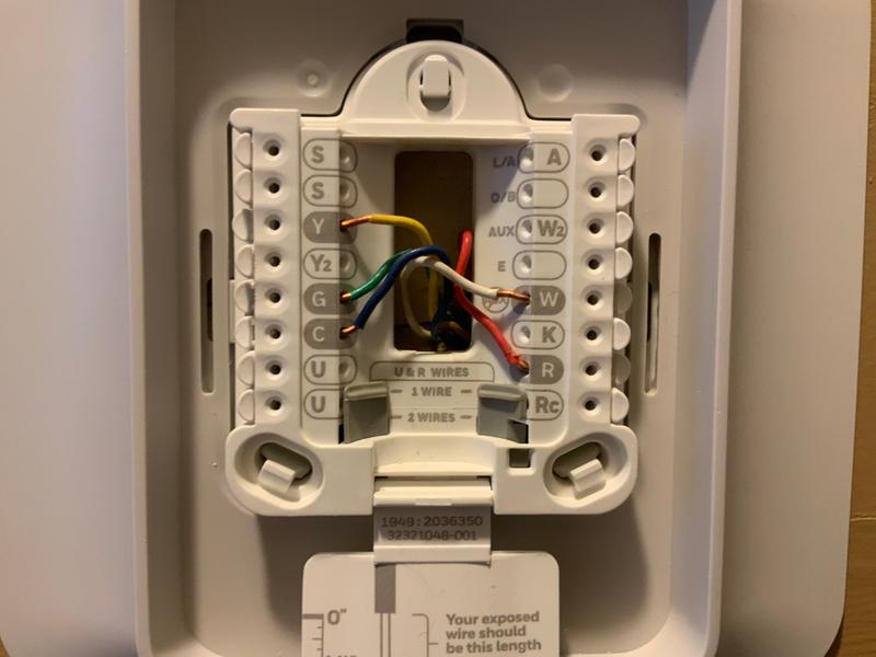
Terminal Designations
Within the comprehensive Honeywell T9 Wiring Diagram, the accurate identification of terminal designations holds paramount importance, as it ensures the proper connection of wires to the thermostat. These terminals serve as the electrical connection points for the thermostat to communicate with the HVAC system and other components. Miswiring or incorrect identification of terminals can lead to malfunctions, safety hazards, and compromised system performance.
- Terminal Markings: Each terminal on the Honeywell T9 thermostat is clearly marked with a letter or number designation. These markings correspond to the specific wires that should be connected to each terminal, as per the wiring diagram.
- Wire Type Compatibility: Different types of wires, such as stranded or solid core, may be required for different terminals. The wiring diagram specifies the appropriate wire type for each terminal to ensure a secure and reliable connection.
- Terminal Blocks: The terminals are typically grouped together in terminal blocks for ease of wiring and organization. Each terminal block may accommodate multiple terminals, each with its own unique designation.
- Advanced Features: Some Honeywell T9 thermostats offer advanced features, such as zone control or remote access, which may require additional terminals for wiring. The wiring diagram provides clear instructions on how to connect these additional components.
By adhering to the terminal designations outlined in the Honeywell T9 Wiring Diagram, HVAC professionals can ensure that the thermostat is wired correctly and functions optimally. Proper wiring ensures accurate temperature control, efficient energy management, and reliable system operation, contributing to a comfortable and energy-efficient indoor environment.
Wire Gauge Recommendations
Within the comprehensive Honeywell T9 Wiring Diagram, accurate wire gauge recommendations play a crucial role in ensuring optimal current flow throughout the system. Selecting the appropriate wire size for each terminal is essential for maintaining electrical safety, preventing overheating, and achieving reliable thermostat operation.
- Electrical Safety: Using the recommended wire gauge helps prevent excessive current draw and potential electrical hazards. Oversized wires can handle higher current without overheating, reducing the risk of electrical fires or damage to the thermostat and connected components.
- Voltage Drop Mitigation: Proper wire gauge selection minimizes voltage drop over the length of the wire. Voltage drop occurs when electrical resistance in the wire causes a reduction in voltage at the load end. Using a larger wire gauge reduces resistance and maintains adequate voltage levels for the thermostat to function correctly.
- Energy Efficiency: Properly sized wires enhance energy efficiency by reducing power loss due to electrical resistance. Thicker wires offer lower resistance, allowing more efficient transfer of electrical energy from the power source to the thermostat and connected devices.
- Code Compliance: Adhering to the wire gauge recommendations in the Honeywell T9 Wiring Diagram ensures compliance with local electrical codes and standards. Using undersized wires can pose safety risks and may result in code violations or failed inspections.
By following the wire gauge recommendations outlined in the Honeywell T9 Wiring Diagram, HVAC professionals can ensure the safe, efficient, and reliable operation of the thermostat. Proper wire sizing contributes to a well-functioning HVAC system that provides optimal temperature control, energy savings, and a comfortable indoor environment.
Compatibility
Within the comprehensive Honeywell T9 Wiring Diagram, the compatibility aspect plays a crucial role in ensuring seamless integration with diverse HVAC systems. This compatibility ensures that the thermostat can effectively control and communicate with various types of HVAC equipment, enabling efficient and reliable temperature management.
- Equipment Types: The wiring diagram clearly outlines the compatibility of the Honeywell T9 thermostat with different types of HVAC equipment, such as gas or electric furnaces, heat pumps, air conditioners, and fan coils. Each equipment type has specific wiring requirements and the diagram provides the necessary information for proper installation.
- Voltage Compatibility: The thermostat’s compatibility extends to different voltage systems commonly used in residential and commercial buildings. The wiring diagram specifies the voltage range that the thermostat can support, ensuring compatibility with both 24V and 120/240V systems.
- Control Capabilities: The compatibility aspect also encompasses the thermostat’s ability to control various heating and cooling stages. The wiring diagram provides guidance on wiring for single-stage, multi-stage, and heat pump systems, ensuring optimal temperature control and energy efficiency.
- Advanced Features: For advanced HVAC systems that incorporate zoning or remote access features, the wiring diagram outlines the compatibility of the Honeywell T9 thermostat with additional modules or accessories. This ensures that the thermostat can seamlessly integrate with these advanced features, providing enhanced comfort and control.
By thoroughly understanding the compatibility aspects outlined in the Honeywell T9 Wiring Diagram, HVAC professionals can confidently select and install the thermostat in a wide range of HVAC systems. This compatibility ensures proper operation, efficient energy management, and a comfortable indoor environment, ultimately contributing to the satisfaction and well-being of building occupants.
Zone Control
Within the comprehensive Honeywell T9 Wiring Diagram, the aspect of zone control holds significant importance in enabling the thermostat to manage multiple heating or cooling zones independently. This advanced feature empowers users to create customized temperature settings for different areas of a building, enhancing comfort and energy efficiency.
- Zoning Hardware: The Honeywell T9 thermostat supports zoning through the integration of additional hardware modules or accessories. These modules allow the thermostat to communicate with zone dampers or valves, which control the flow of air or water to different zones.
- Zone Configuration: The wiring diagram provides detailed instructions on how to configure the thermostat for zone control. This includes specifying the number of zones, assigning zones to specific terminals, and calibrating the thermostat to maintain desired temperatures in each zone.
- Independent Control: With zone control, each zone can be programmed with its own temperature schedule and settings. This allows occupants to customize the temperature in their specific areas, ensuring personalized comfort levels throughout the building.
- Energy Savings: Zone control contributes to energy savings by optimizing heating and cooling based on occupancy and usage patterns. By only conditioning the zones that require it, the system reduces energy consumption and lowers utility bills.
The Honeywell T9 Wiring Diagram’s comprehensive coverage of zone control empowers HVAC professionals to design and implement effective zoning strategies. This advanced feature enhances comfort, energy efficiency, and the overall functionality of the HVAC system, contributing to a more comfortable and cost-effective indoor environment.
Remote Access
Within the comprehensive Honeywell T9 Wiring Diagram, the section on remote access holds significant relevance as it empowers users to control and monitor their thermostats from anywhere, offering convenience and enhanced comfort management.
The wiring diagram provides detailed instructions on connecting the thermostat to a Wi-Fi network, enabling remote access through the Honeywell Home app on smartphones or tablets. This connectivity allows users to adjust temperature settings, create schedules, and monitor energy usage remotely, regardless of their physical location.
Remote access is particularly beneficial in various scenarios:
- Vacation homes: Remotely controlling the thermostat ensures a comfortable indoor temperature upon arrival, eliminating the need to manually adjust settings after traveling.
- Energy management: Real-time energy usage monitoring helps users identify patterns and make informed decisions to reduce energy consumption and save on utility bills.
- Scheduling convenience: Remote access allows users to modify temperature schedules on the go, accommodating unexpected changes in daily routines or weekend getaways.
- Troubleshooting: Remote access enables users to quickly diagnose and resolve minor issues with the thermostat, avoiding the need for in-person maintenance calls.
The Honeywell T9 Wiring Diagram’s clear instructions on remote access empower HVAC professionals to seamlessly integrate this advanced feature into their installations. This understanding allows them to provide clients with a more convenient and energy-efficient thermostat experience, contributing to greater comfort and satisfaction.
Advanced Programming
Within the comprehensive Honeywell T9 Wiring Diagram, the section on advanced programming empowers users with a range of customizable features that enhance comfort, efficiency, and convenience. This advanced programming functionality allows users to tailor the thermostat’s operation to their specific needs and preferences.
- Scheduling: The Honeywell T9 thermostat offers flexible scheduling options, allowing users to program different temperature settings for different times of the day and days of the week. This feature is particularly useful for automating temperature adjustments based on daily routines and occupancy patterns, leading to energy savings and improved comfort.
- Temperature Setbacks: Advanced programming includes the ability to set temperature setbacks, which are temporary reductions in temperature during unoccupied periods or at night. These setbacks help conserve energy without compromising comfort, as the thermostat automatically returns to the desired temperature before occupants return home or wake up.
- Vacation Mode: For extended periods away from home, the vacation mode feature allows users to set a specific temperature range to maintain while they are absent. This mode helps prevent energy waste by keeping the temperature at a constant, unoccupied level, while ensuring that the home does not become too cold or too warm upon return.
- Geofencing: Some Honeywell T9 thermostats support geofencing capabilities, which use a smartphone app to detect when occupants are approaching or leaving home. By leveraging location-based technology, the thermostat can automatically adjust its settings to optimize comfort and energy efficiency based on occupancy.
These advanced programming features, as outlined in the Honeywell T9 Wiring Diagram, provide users with a high level of control over their home’s temperature management. By understanding and implementing these programming options, HVAC professionals can help their clients achieve greater comfort, energy savings, and peace of mind.
Troubleshooting
Within the comprehensive Honeywell T9 Wiring Diagram, the troubleshooting aspect holds significant importance as it empowers HVAC professionals and homeowners alike to identify and resolve common wiring-related issues with the thermostat. This section of the diagram provides clear guidance and instructions, enabling users to restore the thermostat’s functionality and maintain a comfortable indoor environment.
- Identifying Loose Connections: The wiring diagram helps users identify potential loose connections within the thermostat’s wiring terminals. Loose connections can lead to intermittent operation, incorrect temperature readings, or even complete system failure. The diagram provides visual cues and step-by-step instructions on how to securely tighten these connections, ensuring proper electrical contact.
- Diagnosing Short Circuits: Short circuits can occur when two wires come into contact, creating an unintended electrical path. The wiring diagram includes troubleshooting steps to help identify potential short circuits by measuring electrical continuity between terminals. By resolving short circuits promptly, users can prevent damage to the thermostat or other components of the HVAC system.
- Resolving Open Circuits: Open circuits occur when a wire is broken or disconnected, interrupting the electrical flow. The wiring diagram provides guidance on how to locate and repair open circuits, ensuring that the thermostat receives the necessary power and signals to function correctly.
- Understanding Error Codes: Some Honeywell T9 thermostats feature a display that can show error codes when certain issues are detected. The wiring diagram includes a table of error codes and their corresponding troubleshooting procedures. By understanding these error codes, users can quickly identify the root cause of the problem and take appropriate corrective actions.
The troubleshooting aspect of the Honeywell T9 Wiring Diagram empowers users to effectively diagnose and resolve common wiring-related issues with the thermostat. By following the provided instructions and guidance, users can restore the thermostat’s functionality, ensure accurate temperature control, and maintain a comfortable and energy-efficient indoor environment.
Safety Precautions
Within the context of the Honeywell T9 Wiring Diagram, the aspect of “Safety Precautions” holds paramount importance, as it underscores the critical need to adhere to established safety protocols when handling electrical wiring. These precautions aim to safeguard individuals from potential hazards and ensure the proper functioning of the thermostat and the HVAC system as a whole.
- Electrical Hazards: Working with electrical wiring involves the risk of electric shock, burns, and even electrocution. The wiring diagram emphasizes the importance of de-energizing the circuit before performing any electrical work and using insulated tools and personal protective equipment (PPE) to minimize the risk of contact with live wires.
- Fire Prevention: Improper wiring or loose connections can lead to overheating and potential fire hazards. The wiring diagram provides guidelines for proper wire sizing, terminal tightening, and the use of appropriate electrical components to prevent excessive heat buildup and reduce the risk of electrical fires.
- Compliance with Codes: Safety precautions also encompass compliance with local electrical codes and standards. The wiring diagram aligns with established codes to ensure that installations meet the minimum safety requirements and adhere to industry best practices.
- Manufacturer’s Instructions: The Honeywell T9 Wiring Diagram complements the manufacturer’s instructions by providing detailed visual guidance on wiring connections. Following these instructions carefully helps ensure that the thermostat is wired correctly, avoiding potential safety hazards and ensuring optimal performance.
By adhering to the safety precautions outlined in the Honeywell T9 Wiring Diagram, HVAC professionals and homeowners can mitigate risks associated with electrical wiring, promote a safe working environment, and maintain a reliable and efficient HVAC system. Neglecting these precautions can have severe consequences, compromising safety and potentially leading to property damage or personal injury.
Code Compliance
Within the comprehensive Honeywell T9 Wiring Diagram, the emphasis on code compliance is a critical component, as it ensures the safe and installation, operation, and maintenance of the thermostat. Adhering to local electrical codes and regulations serves as a cornerstone for upholding safety standards and minimizing potential hazards within electrical systems.
Electrical codes and regulations are established to safeguard individuals, property, and the integrity of electrical installations. These codes provide guidelines for proper wiring practices, component selection, and installation techniques. By adhering to these codes, HVAC professionals can mitigate risks associated with electrical fires, electric shock, and other safety concerns.
The Honeywell T9 Wiring Diagram incorporates these code requirements by providing clear instructions and visual cues that guide installers towards compliant wiring practices. This includes specifying appropriate wire gauges, terminal connections, and overcurrent protection measures. By following the diagram’s instructions, installers can ensure that the thermostat is wired in accordance with established safety standards.
Real-life examples of code compliance within the Honeywell T9 Wiring Diagram include proper grounding techniques, the use of listed electrical components, and adherence to specific wire color coding conventions. These measures contribute to the overall safety and reliability of the thermostat installation.
Understanding the importance of code compliance in the Honeywell T9 Wiring Diagram enables HVAC professionals to make informed decisions during installation and maintenance. By prioritizing code compliance, they not only ensure the safety of the installation but also contribute to a more efficient and reliable HVAC system. This understanding empowers professionals to confidently navigate electrical wiring tasks, minimize potential hazards, and maintain a high level of professionalism in their work.
Warranty Information
Within the comprehensive Honeywell T9 Wiring Diagram, the inclusion of warranty information plays a critical role in providing users with peace of mind and ensuring the long-term reliability of their thermostat installation. The warranty serves as a guarantee from the manufacturer that the thermostat and its components will perform as intended for a specified period of time.
The warranty information typically outlines the terms and conditions of the coverage, including the duration of the warranty, the parts and services covered, and the process for filing a warranty claim. By understanding the warranty information, users can make informed decisions about the installation and maintenance of their thermostat, ensuring that they are protected in the event of any unexpected issues or defects.
Real-life examples of warranty information within the Honeywell T9 Wiring Diagram include:
- The length of the warranty coverage, which may vary depending on the specific thermostat model and manufacturer’s policies.
- A clear definition of what components and parts are covered under the warranty, such as the thermostat itself, sensors, and wiring.
- Instructions on how to register the warranty and the process for filing a claim if necessary.
Understanding the practical applications of warranty information empowers users to:
- Make well-informed Entscheidungen about their thermostat purchase and installation, considering the length and coverage of the warranty.
- Ensure proper installation and maintenance of the thermostat to maximize its lifespan and minimize the risk of warranty claims.
- File warranty claims efficiently and effectively in the event of any issues, ensuring timely repairs or replacements.
In conclusion, the warranty information included in the Honeywell T9 Wiring Diagram is a valuable resource that provides users with peace of mind, protects their investment, and ensures the long-term reliability of their thermostat installation.


Related Posts


