A Honeywell Ct410b Wiring Diagram is a technical document that provides a visual representation of the electrical connections within a Honeywell Ct410b programmable thermostat. It outlines the specific wiring configuration required to connect the thermostat to an HVAC system.
Wiring diagrams are essential for accurate and safe installation of thermostats. They ensure that the thermostat is properly connected to the heating and cooling equipment, allowing for optimal temperature control and efficient system operation. Benefits include improved energy efficiency, enhanced comfort, and reduced risk of electrical hazards.
A key historical development in wiring diagrams is the adoption of standardized color codes for electrical wires. This standardization enables easier identification and tracing of wires within complex systems, reducing errors and improving overall safety.
Delving into the essential aspects of a Honeywell Ct410b Wiring Diagram provides a comprehensive understanding of this technical document. These aspects encompass various dimensions, each contributing to the effective installation and operation of the thermostat.
- Wiring Configuration: Outlines the specific arrangement of electrical connections between the thermostat and HVAC system components.
- Terminal Identification: Identifies the designated terminals on the thermostat and HVAC equipment for proper wire connections.
- Wire Gauge and Type: Specifies the appropriate wire size and type for each connection, ensuring optimal current flow and system performance.
- Power Supply: Indicates the electrical requirements for the thermostat, including voltage and current.
- System Compatibility: Ensures compatibility between the thermostat and the specific HVAC system being controlled.
- Safety Features: Highlights any built-in safety features, such as overcurrent protection or fault detection mechanisms.
- Troubleshooting Guide: Provides guidance on identifying and resolving common wiring-related issues.
- Installation Instructions: Offers step-by-step instructions for safe and efficient thermostat installation.
- Technical Specifications: Lists the technical parameters and performance characteristics of the thermostat.
- Compliance Standards: Indicates adherence to relevant electrical and safety codes and standards.
Understanding these key aspects enables technicians and homeowners to confidently install and operate the Honeywell Ct410b programmable thermostat, ensuring accurate temperature control, efficient energy management, and reliable system performance.
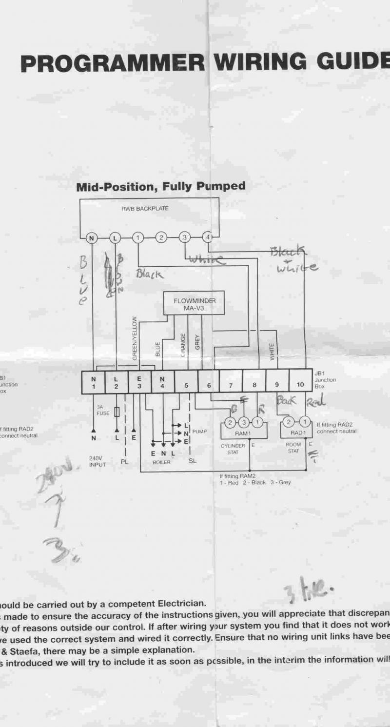
Wiring Configuration
Within the Honeywell Ct410b Wiring Diagram, the aspect of Wiring Configuration holds paramount importance, dictating the precise arrangement of electrical connections between the thermostat and the HVAC system’s components. This configuration ensures seamless communication and control between these elements, enabling efficient and reliable operation of the heating and cooling system.
- Terminal Connections: The wiring diagram specifies the designated terminals on both the thermostat and HVAC equipment where electrical wires are to be connected. Each terminal is assigned a specific function, such as power supply, heating control, or cooling operation. Proper identification and connection of wires to the correct terminals are crucial for the system to function as intended.
- Wire Type and Gauge: The diagram also indicates the appropriate type and gauge of electrical wire to be used for each connection. Wire type refers to the material and insulation, while gauge represents the thickness or cross-sectional area of the wire. Selecting the correct wire type and gauge is essential to ensure adequate current flow and prevent overheating or damage to the system.
- Power Supply: The wiring diagram specifies the electrical requirements of the thermostat, including the voltage and current needed for its operation. This information guides the selection of the appropriate power source and ensures that the thermostat receives the necessary power to operate effectively.
- System Compatibility: The diagram ensures compatibility between the thermostat and the specific HVAC system being controlled. Different systems may have varying wiring configurations and requirements, and the diagram ensures that the thermostat is compatible with the system’s electrical specifications and control logic.
Understanding and adhering to the Wiring Configuration aspect of the Honeywell Ct410b Wiring Diagram is critical for safe and efficient installation and operation of the thermostat. It ensures proper communication between the thermostat and HVAC components, enabling precise temperature control, optimal system performance, and reduced risk of electrical hazards.
Terminal Identification
Within the context of the Honeywell Ct410b Wiring Diagram, Terminal Identification plays a pivotal role in ensuring the proper and safe operation of the thermostat and the entire HVAC system. This aspect of the wiring diagram serves as a roadmap, guiding the technician or installer in connecting the thermostat to the designated terminals on the HVAC equipment.
The accurate identification of terminals is critical because each terminal serves a specific function within the system. Miswiring or incorrect connections can lead to malfunctions, reduced efficiency, or even safety hazards. The wiring diagram provides clear instructions on which wires should be connected to which terminals, eliminating guesswork and reducing the risk of errors. For instance, the diagram specifies the terminals for power supply, heating control, cooling operation, and any additional features or accessories.
Real-life examples further illustrate the importance of Terminal Identification. Consider a scenario where a technician connects the wire for the heating system to the terminal designated for the cooling system. This error could result in the heating system being activated when cooling is desired, leading to discomfort and wasted energy. Conversely, a proper connection ensures that the heating system is activated only when needed, optimizing energy efficiency and maintaining desired temperatures.
Understanding Terminal Identification is not only crucial for installation but also for troubleshooting and maintenance. By referring to the wiring diagram, technicians can quickly identify the correct terminals to check for loose connections, voltage readings, or other diagnostic procedures. This knowledge empowers them to resolve issues efficiently, minimizing downtime and ensuring the continued smooth operation of the HVAC system.
In summary, Terminal Identification is an indispensable component of the Honeywell Ct410b Wiring Diagram. It provides precise guidance on connecting the thermostat to the HVAC equipment, ensuring proper system operation, safety, and energy efficiency. Understanding and adhering to the terminal identification guidelines outlined in the wiring diagram are essential for successful installation, troubleshooting, and maintenance of the HVAC system.
Wire Gauge and Type
Within the comprehensive Honeywell Ct410b Wiring Diagram, the aspect of Wire Gauge and Type emerges as a crucial element, dictating the selection and use of electrical wires for connecting the thermostat to the HVAC system. The appropriate wire gauge and type play a pivotal role in ensuring optimal current flow, system performance, and long-term reliability.
- Conductor Material: The wiring diagram specifies the type of conductor material, typically copper or aluminum, to be used for the electrical wires. Copper is commonly preferred for its superior conductivity and durability, while aluminum may be used in certain cost-sensitive applications.
- Wire Gauge: The diagram indicates the appropriate wire gauge, which refers to the thickness or cross-sectional area of the wire. Thicker gauge wires offer lower resistance and can carry higher currents, while thinner gauge wires have higher resistance and are suitable for lower current applications.
- Insulation Type: The wiring diagram specifies the type of insulation for the electrical wires, such as PVC, rubber, or Teflon. Insulation is crucial for preventing electrical shocks and short circuits, and different types of insulation offer varying levels of protection and durability.
- Wire Color Coding: The diagram may also include color coding guidelines for the wires, which helps in easy identification and tracing during installation and troubleshooting. Standard color codes are often used to differentiate between different types of wires, such as black for power, red for heating, and blue for cooling.
Adhering to the specified Wire Gauge and Type guidelines in the Honeywell Ct410b Wiring Diagram is paramount for several reasons. Proper wire selection ensures that the electrical current can flow efficiently through the system, minimizing power loss and potential overheating. It also helps prevent voltage drops, which can affect the performance and lifespan of the thermostat and HVAC components. Moreover, using the correct wire type and gauge reduces the risk of electrical hazards, such as short circuits or fires, ensuring a safe and reliable operation of the system.
Power Supply
Within the comprehensive Honeywell Ct410b Wiring Diagram, the aspect of Power Supply holds utmost importance, outlining the electrical specifications necessary for the thermostat to function effectively. Understanding and adhering to these requirements ensure the safe and efficient operation of the thermostat and the entire HVAC system.
- Voltage Requirements: The wiring diagram specifies the voltage at which the thermostat operates, typically ranging from 24 volts to 240 volts. Incorrect voltage can damage the thermostat or impair its performance.
- Current Consumption: The diagram indicates the amount of electrical current the thermostat draws from the power source. This information is crucial for selecting the appropriate power supply and wiring.
- Power Source: The wiring diagram may specify the type of power source required for the thermostat, such as batteries, a low-voltage transformer, or direct connection to the HVAC system’s electrical panel.
Comprehending the Power Supply requirements outlined in the Honeywell Ct410b Wiring Diagram is essential for several reasons. Firstly, it ensures that the thermostat receives the correct voltage and current to operate properly. Secondly, it helps prevent electrical hazards, such as overcurrent or short circuits, which can damage the thermostat or the HVAC system. Thirdly, it enables the selection of compatible components, such as transformers or power supplies, that meet the specific electrical requirements of the thermostat.
System Compatibility
Within the comprehensive Honeywell Ct410b Wiring Diagram, the aspect of System Compatibility assumes paramount importance, ensuring seamless communication and control between the thermostat and the HVAC system. It dictates the specific electrical and communication protocols that must be adhered to for effective integration and operation.
- Electrical Compatibility: The wiring diagram outlines the specific voltage, current, and power requirements of the thermostat. It ensures that the thermostat is compatible with the electrical characteristics of the HVAC system, preventing damage or malfunctions due to incorrect electrical connections.
- Communication Protocol: The diagram specifies the communication protocol used by the thermostat to interact with the HVAC system. Common protocols include proprietary wireless technologies, industry-standard wired connections, or emerging smart home platforms. Ensuring compatibility ensures seamless data exchange and control commands between the thermostat and the HVAC components.
- Hardware Configuration: The wiring diagram provides guidance on the specific terminals and connections required to interface the thermostat with the HVAC system. It outlines the compatibility of the thermostat’s terminals with the corresponding terminals on the HVAC equipment, ensuring proper signal transmission and control.
- Software Compatibility: In the case of programmable or smart thermostats, the wiring diagram may also indicate software compatibility requirements. It ensures that the thermostat’s software is compatible with the firmware or operating system of the HVAC system, allowing for proper functionality and feature integration.
Understanding and adhering to the System Compatibility guidelines outlined in the Honeywell Ct410b Wiring Diagram are essential for successful installation and operation of the thermostat. It ensures that the thermostat can effectively communicate with and control the HVAC system, resulting in optimal temperature regulation, energy efficiency, and user convenience.
Safety Features
Within the comprehensive Honeywell Ct410b Wiring Diagram, the aspect of Safety Features takes center stage, outlining critical mechanisms and measures incorporated to ensure the safe and reliable operation of the thermostat and the HVAC system it controls. These safety features safeguard against potential hazards, protecting both equipment and individuals from harm.
- Overcurrent Protection: The wiring diagram may specify built-in overcurrent protection devices, such as fuses or circuit breakers, to prevent damage to the thermostat or HVAC components in the event of excessive electrical current. Overcurrent protection ensures that the electrical circuit is interrupted before dangerous levels of current can flow, minimizing the risk of electrical fires or equipment failure.
- Fault Detection Mechanisms: The diagram may include fault detection mechanisms that monitor the electrical system for abnormal conditions, such as short circuits or ground faults. In the event of a fault, these mechanisms trigger an alarm or shut down the system to prevent further damage or electrical hazards. Fault detection is crucial for identifying and isolating electrical issues before they escalate into more severe problems.
- Thermal Overload Protection: Some thermostats incorporate thermal overload protection to prevent overheating. This feature monitors the internal temperature of the thermostat and disconnects power if it exceeds safe operating limits. Thermal overload protection safeguards the thermostat from potential fire hazards and ensures its longevity.
- Isolation Transformers: In certain applications, the wiring diagram may specify the use of isolation transformers to provide electrical isolation between the thermostat and the HVAC system. Isolation transformers enhance safety by preventing electrical shock and ground loops, which can interfere with the proper operation of the thermostat and HVAC components.
Understanding and adhering to the Safety Features outlined in the Honeywell Ct410b Wiring Diagram are crucial for ensuring a safe and reliable HVAC system operation. These features provide multiple layers of protection, reducing the risk of electrical hazards, equipment damage, and potential injuries. By incorporating built-in safety mechanisms, the thermostat and HVAC system are equipped to handle abnormal conditions and protect both the system and its users.
Troubleshooting Guide
Within the context of the Honeywell Ct410b Wiring Diagram, the Troubleshooting Guide emerges as an indispensable tool, empowering technicians and homeowners alike to identify and resolve common wiring-related issues that may arise during installation, operation, or maintenance of the thermostat and HVAC system. This guide serves as a valuable resource, providing step-by-step instructions and diagnostic techniques to address a wide range of potential problems.
The Troubleshooting Guide is intricately connected to the Honeywell Ct410b Wiring Diagram, as it relies on the diagram’s detailed instructions and schematics to pinpoint the source of wiring-related issues. The guide complements the diagram by offering practical solutions and troubleshooting tips, enabling users to rectify errors and restore the system to optimal operation.
Real-life examples further illustrate the significance of the Troubleshooting Guide. Consider a scenario where a technician encounters an issue with the thermostat not responding to commands. By referring to the Troubleshooting Guide, the technician can systematically check for loose connections, faulty wires, or incorrect terminal assignments, ultimately resolving the problem and ensuring proper communication between the thermostat and the HVAC system.
Furthermore, the Troubleshooting Guide provides valuable insights into the practical applications of the Honeywell Ct410b Wiring Diagram. It empowers users to not only install and configure the thermostat but also to maintain and troubleshoot the system independently. This understanding enhances the overall user experience, reduces reliance on external support, and promotes a sense of self-reliance in managing the HVAC system.
In summary, the Troubleshooting Guide plays a critical role in conjunction with the Honeywell Ct410b Wiring Diagram. It provides a comprehensive resource for identifying and resolving common wiring-related issues, empowering users to maintain a fully functional and efficient thermostat and HVAC system.
Installation Instructions
Within the framework of the Honeywell Ct410b Wiring Diagram, the Installation Instructions serve as a critical component, providing a detailed roadmap for the safe and efficient installation of the thermostat. These instructions are intricately connected to the wiring diagram, as they guide users through the physical implementation of the electrical connections outlined in the diagram.
The Installation Instructions offer a step-by-step approach, breaking down the installation process into manageable tasks. They specify the necessary tools and materials, ensuring that users are well-equipped to complete the installation successfully. The instructions also include clear and concise diagrams, illustrating the physical layout of the thermostat and its connections to the HVAC system.
Real-life examples underscore the importance of the Installation Instructions. Consider a scenario where a homeowner attempts to install the thermostat without referring to the instructions. This could lead to incorrect wiring, resulting in malfunctioning of the thermostat or even electrical hazards. By contrast, following the Installation Instructions systematically reduces the risk of errors and ensures a secure and functional installation.
Moreover, the Installation Instructions empower users to take ownership of their HVAC system maintenance. By understanding the proper installation procedures, homeowners can perform basic troubleshooting and maintenance tasks, reducing reliance on external support and promoting self-sufficiency.
In summary, the Installation Instructions are an indispensable part of the Honeywell Ct410b Wiring Diagram, providing clear and comprehensive guidance for safe and efficient thermostat installation. They empower users to confidently undertake the installation process, ensuring the proper functioning of the thermostat and the HVAC system as a whole.
Technical Specifications
Within the comprehensive Honeywell Ct410b Wiring Diagram, the Technical Specifications section holds a critical position, providing essential information about the technical parameters and performance characteristics of the thermostat. This information is vital for ensuring compatibility, efficient operation, and adherence to regulatory standards.
- Electrical Ratings: This section specifies the electrical requirements of the thermostat, including voltage, amperage, and power consumption. Understanding these ratings is crucial for selecting the appropriate power source and ensuring safe operation.
- Temperature Range: The technical specifications outline the range of temperatures that the thermostat can measure and control. This information helps determine whether the thermostat is suitable for the specific heating and cooling needs of a particular application.
- Accuracy and Resolution: These specifications indicate the precision and sensitivity of the thermostat’s temperature sensing and control capabilities. Higher accuracy and resolution result in more precise temperature regulation.
- Display and Interface: The technical specifications describe the type of display and user interface provided by the thermostat. This information is important for assessing the readability, ease of use, and overall user experience.
Understanding and considering the Technical Specifications outlined in the Honeywell Ct410b Wiring Diagram empower users to make informed decisions during thermostat selection and installation. By matching the thermostat’s technical parameters to the specific requirements of the HVAC system and application, optimal performance, energy efficiency, and user satisfaction can be achieved.
Compliance Standards
Within the context of the Honeywell Ct410b Wiring Diagram, the aspect of Compliance Standards holds paramount importance, indicating the thermostat’s adherence to relevant electrical and safety codes and standards. This section of the wiring diagram provides assurance that the thermostat meets the established guidelines and regulations set forth by regulatory bodies to ensure safe and reliable operation.
- National Electrical Code (NEC) Compliance: The NEC outlines a comprehensive set of electrical safety regulations aimed at preventing electrical fires, shocks, and other hazards. Compliance with NEC standards ensures that the thermostat’s electrical design and installation meet these requirements, minimizing the risk of electrical accidents.
- Underwriters Laboratories (UL) Listing: UL is an independent safety certification organization that evaluates products against rigorous safety standards. A UL listing indicates that the thermostat has undergone rigorous testing and meets UL’s safety requirements, providing users with peace of mind.
- Canadian Standards Association (CSA) Certification: CSA is the leading standards development organization in Canada, responsible for establishing safety and quality standards for various products, including electrical equipment. CSA certification indicates that the thermostat meets Canadian safety requirements, ensuring compliance with local regulations.
- International Electrotechnical Commission (IEC) Conformity: IEC is an international organization that develops and publishes international standards for electrical and electronic products. IEC conformity signifies that the thermostat meets globally recognized safety and performance standards, enabling its use in various countries.
Adhering to Compliance Standards outlined in the Honeywell Ct410b Wiring Diagram is crucial for several reasons. It ensures the thermostat is designed, manufactured, and installed according to established safety guidelines, reducing the risk of electrical hazards and ensuring the protection of both property and individuals. Compliance also demonstrates the manufacturer’s commitment to quality and adherence to industry best practices, fostering trust and confidence among users.


Related Posts


