Definition: A Harley Turn Signal Wiring Diagram is a visual representation of the electrical connections required to install and operate turn signals on a Harley-Davidson motorcycle. It outlines the proper routing of wires, connection points, and component integration, ensuring that turn signals function correctly.
Importance and benefits: Understanding a Harley Turn Signal Wiring Diagram is crucial for safe and legal motorcycle operation. It helps prevent improper wiring, electrical malfunctions, and potential accidents caused by inoperative turn signals. It allows riders to troubleshoot and repair turn signal issues independently, saving time and expenses.
Historical development: The use of turn signals on motorcycles has evolved over time. Early models relied on simple mechanical devices, but as electrical systems became more sophisticated, wiring diagrams became essential to guide the proper installation and operation of turn signals. Today, Harley Turn Signal Wiring Diagrams are an integral part of motorcycle maintenance and repair manuals.
This article will delve into the intricacies of Harley Turn Signal Wiring Diagrams, providing comprehensive technical guidance on their interpretation and application. It will cover essential electrical concepts, component identification, proper wiring techniques, and practical tips to ensure the reliable operation of turn signals, enhancing riding safety and legal compliance.
Understanding the essential aspects of a Harley Turn Signal Wiring Diagram is crucial for the safe and reliable operation of turn signals on Harley-Davidson motorcycles. These diagrams provide visual instructions on the proper electrical connections, component integration, and wire routing, ensuring that turn signals function correctly. Here are eight key aspects to consider:
- Components: Identifying the components involved in a turn signal system, such as the turn signal switch, flasher relay, and turn signal bulbs.
- Connections: Understanding the proper electrical connections between components, including wire colors and terminal locations.
- Routing: Determining the correct routing of wires to avoid interference with other electrical systems and ensure proper signal operation.
- Troubleshooting: Using the diagram to diagnose and repair common turn signal issues, such as inoperative bulbs or intermittent flashing.
- Customization: Modifying the wiring diagram to accommodate custom turn signal installations or accessories.
- Safety: Ensuring that the wiring diagram complies with electrical safety standards and best practices.
- Legal compliance: Verifying that the turn signal system meets legal requirements for motorcycle operation.
- Maintenance: Using the diagram for routine maintenance and inspection of the turn signal system.
These aspects are interconnected and essential for a comprehensive understanding of Harley Turn Signal Wiring Diagrams. By considering these factors, riders can ensure the proper installation, operation, and maintenance of their turn signals, enhancing safety and legal compliance on the road.
Components
In the context of a Harley Turn Signal Wiring Diagram, identifying the components involved in a turn signal system is crucial because these components form the foundation of the electrical circuit that enables turn signals to function properly. The turn signal switch initiates the turn signal operation when activated by the rider, sending a signal to the flasher relay. The flasher relay then generates the intermittent flashing pattern for the turn signals, which is essential for indicating the intended direction of travel to other road users. Finally, the turn signal bulbs provide the visual indication of the turn signal activation, emitting light to alert surrounding vehicles and pedestrians.
Understanding the relationship between these components is vital for troubleshooting and repairing turn signal issues. For example, if a turn signal bulb is not illuminating, the issue could lie with the bulb itself, the wiring connecting the bulb to the flasher relay, or the flasher relay itself. By referring to the Harley Turn Signal Wiring Diagram, riders can trace the electrical connections and identify the specific component causing the malfunction.
In summary, identifying the components involved in a turn signal system is a critical aspect of understanding Harley Turn Signal Wiring Diagrams. This knowledge empowers riders to maintain and repair their turn signal systems effectively, ensuring the safe and legal operation of their motorcycles on the road.
Connections
In the context of Harley Turn Signal Wiring Diagrams, understanding the proper electrical connections between components is paramount. These connections ensure that the turn signals function correctly, providing visual indications of the rider’s intended direction of travel. Various factors contribute to proper electrical connections, including wire colors, terminal locations, and component compatibility.
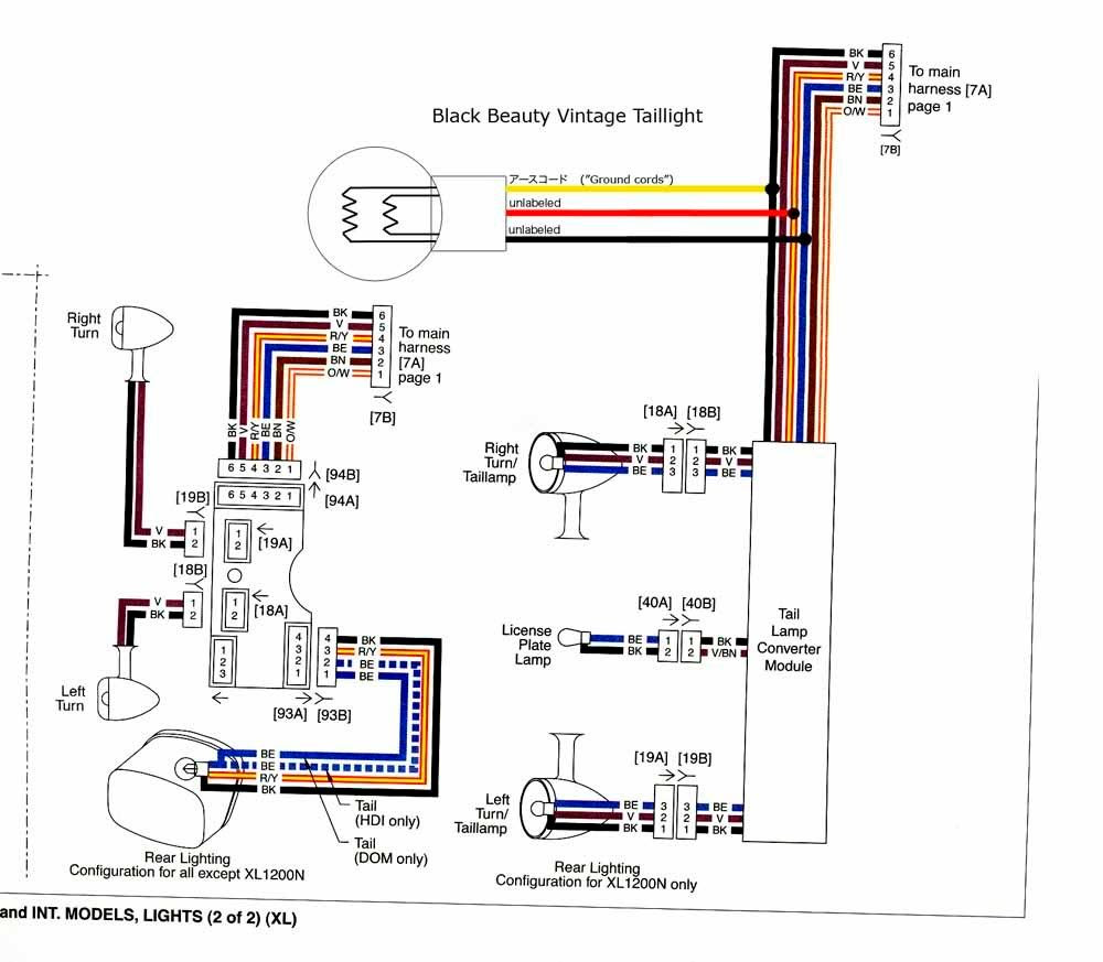
- Wire Colors: Harley Turn Signal Wiring Diagrams use standardized wire colors to designate specific functions. For instance, green wires typically indicate the ground connection, while brown wires often carry the turn signal power. Understanding these color codes simplifies the identification of wires during installation and troubleshooting.
- Terminal Locations: Turn signal components have designated terminals for electrical connections. The wiring diagram specifies the correct terminal for each wire, ensuring proper signal flow. Incorrect terminal connections can result in malfunctioning turn signals or electrical shorts.
- Component Compatibility: When modifying or replacing turn signal components, it is crucial to consider component compatibility. Turn signal switches, flasher relays, and bulbs must be compatible with the motorcycle’s electrical system. Incompatible components can lead to improper signal operation or electrical damage.
- Ground Connections: Proper grounding is essential for the correct functioning of turn signals. The wiring diagram indicates the designated grounding points on the motorcycle’s frame or other components. A secure ground connection provides a complete electrical circuit, allowing the turn signals to operate reliably.
Understanding the proper electrical connections between components in a Harley Turn Signal Wiring Diagram is vital for ensuring the safe and legal operation of turn signals. By adhering to the specified wire colors, terminal locations, and component compatibility, riders can maintain and repair their turn signal systems effectively, enhancing their visibility and safety on the road.
Routing
In the context of Harley Turn Signal Wiring Diagrams, the correct routing of wires is crucial to prevent interference with other electrical systems and ensure the proper operation of turn signals. Strategic wire placement minimizes the risk of short circuits, electrical noise, and malfunctioning components, contributing to the overall reliability and safety of the motorcycle’s electrical system.
- Avoiding Electrical Interference: Routing wires away from sources of electrical interference, such as ignition coils and spark plug wires, prevents unwanted electrical signals from disrupting the turn signal circuit. This ensures that turn signals operate consistently and reliably without flickering or malfunctioning.
- Preventing Wire Damage: Wires should be routed to avoid areas prone to heat, vibration, and mechanical stress. Proper routing protects the wires from damage, ensuring long-term reliability and preventing potential electrical hazards.
- Facilitating Maintenance and Troubleshooting: Wires routed in an organized and accessible manner simplify maintenance and troubleshooting. Technicians can easily trace and inspect wires, identify potential issues, and perform repairs efficiently.
- Compliance with Standards: Adhering to proper routing practices ensures compliance with industry standards and best practices for electrical installations. This contributes to the overall safety and reliability of the motorcycle’s electrical system.
Understanding the principles of wire routing empowers riders to maintain and modify their Harley Turn Signal Wiring Diagrams effectively. By following recommended routing guidelines, riders can prevent electrical issues, enhance the performance of their turn signals, and ensure the safe and reliable operation of their motorcycles.
Troubleshooting
Troubleshooting is a critical component of Harley Turn Signal Wiring Diagrams, providing a systematic approach to diagnosing and repairing common turn signal issues. The diagram serves as a visual guide, enabling riders to trace electrical connections, identify faulty components, and determine the root cause of turn signal malfunctions.
Real-life examples of troubleshooting using Harley Turn Signal Wiring Diagrams include:
- Diagnosing inoperative turn signal bulbs by checking for continuity in the circuit and identifying any breaks or loose connections.
- Resolving intermittent flashing by inspecting the flasher relay and replacing it if faulty.
- Tracing wire connections to locate shorts or grounds that may disrupt turn signal operation.
Understanding how to troubleshoot using Harley Turn Signal Wiring Diagrams empowers riders to maintain and repair their turn signals effectively, ensuring the safety and reliability of their motorcycles. By following the steps outlined in the diagram, they can quickly identify and address common issues, minimizing downtime and maximizing riding enjoyment.
Customization
Customization is a key consideration within the realm of Harley Turn Signal Wiring Diagrams. Modifying the diagram allows riders to tailor their turn signal systems to suit specific preferences or accommodate custom installations. This empowers them to enhance the functionality, appearance, and overall riding experience of their motorcycles.
- Custom Turn Signal Selection: The wiring diagram can be modified to integrate different types of turn signals, such as LED or sequential turn signals, offering riders a range of options to suit their aesthetic and performance requirements.
- Integration of Additional Lighting: Riders can incorporate additional lighting into their turn signal system, such as running lights or brake lights, enhancing visibility and safety on the road.
- Compatibility with Custom Components: When installing aftermarket turn signals or accessories, riders may need to modify the wiring diagram to ensure compatibility with the motorcycle’s electrical system.
- Tailoring to Specific Riding Styles: Modifications to the wiring diagram can accommodate specific riding styles, such as long-distance touring or off-road riding, by optimizing turn signal performance for different conditions.
Customization of Harley Turn Signal Wiring Diagrams offers a myriad of benefits, enabling riders to personalize their motorcycles, enhance safety, and tailor their turn signal systems to suit their individual needs and preferences. Understanding the principles of customization empowers riders to make informed decisions and implement modifications safely and effectively.
Safety
Within the realm of Harley Turn Signal Wiring Diagrams, the aspect of “Safety: Ensuring that the wiring diagram complies with electrical safety standards and best practices” takes center stage. This involves adhering to established guidelines and industry norms to guarantee the safe and reliable operation of turn signals, minimizing the risk of electrical hazards and ensuring the protection of both the rider and the motorcycle.
- Proper Insulation and Protection: Wiring diagrams specify the use of properly insulated wires and protective measures, such as wire looms and grommets, to prevent electrical shorts and protect wires from damage caused by heat, vibration, and external elements.
- Circuit Protection: Diagrams incorporate appropriate fuses or circuit breakers to safeguard electrical components and prevent damage in the event of electrical overloads or short circuits, reducing the risk of fires and electrical failures.
- Grounding and Bonding: Proper grounding and bonding techniques, as outlined in the wiring diagram, ensure that electrical current flows safely through designated paths, minimizing the risk of stray voltage and electrical shocks.
- Compliance with Regulations: Adhering to relevant electrical safety standards and regulations, as reflected in the wiring diagram, demonstrates the motorcycle’s compliance with legal requirements and industry best practices, ensuring the safety of the rider and the motorcycle’s electrical system.
By incorporating these safety considerations into Harley Turn Signal Wiring Diagrams, manufacturers and riders alike can ensure that turn signals function not only effectively but also safely, reducing the likelihood of electrical problems and enhancing the overall safety of the motorcycle on the road.
Legal compliance
Within the context of Harley Turn Signal Wiring Diagrams, legal compliance holds paramount importance. Motorcycle turn signals are mandated by law in most jurisdictions to ensure the safety of riders and other road users. Harley Turn Signal Wiring Diagrams provide the necessary electrical instructions to install and operate turn signals that meet these legal requirements.
Verifying legal compliance involves ensuring that the turn signal system adheres to specific regulations, such as:
- Turn signals must be visible from a specified distance in both daylight and darkness.
- Turn signals must flash at a specific rate to attract attention without being distracting.
- Turn signals must be self-canceling to prevent them from remaining activated after a turn is completed.
Harley Turn Signal Wiring Diagrams incorporate these legal requirements into their design. By following the instructions provided in the diagram, motorcycle owners can be confident that their turn signals meet all applicable laws and regulations.
In summary, legal compliance is a critical aspect of Harley Turn Signal Wiring Diagrams, ensuring that motorcycles are equipped with turn signals that enhance rider safety and comply with legal mandates. Understanding the connection between legal compliance and Harley Turn Signal Wiring Diagrams is essential for responsible motorcycle ownership and operation.
Maintenance
In the realm of Harley Turn Signal Wiring Diagrams, maintenance takes center stage as a critical aspect ensuring the reliability and safety of a motorcycle’s turn signal system. The diagram serves as an essential guide for routine maintenance and inspection procedures, empowering riders to proactively identify and address potential issues before they escalate into more significant problems.
- Bulb Inspection: Regularly checking turn signal bulbs for proper illumination and replacing any burned-out bulbs is crucial. The wiring diagram provides the necessary information to locate and access the bulbs for inspection.
- Connector Examination: Inspecting electrical connectors for corrosion, loose connections, or damage is vital for maintaining optimal electrical flow. The diagram helps identify the location of connectors and provides guidance on proper cleaning or replacement techniques.
- Wire Inspection: Periodically examining turn signal wires for damage, fraying, or insulation breaches is essential to prevent electrical shorts or malfunctions. The diagram aids in tracing wire paths, identifying potential problem areas, and ensuring secure connections.
- Grounding Verification: Verifying the integrity of grounding points is critical to ensure proper electrical functioning. The diagram indicates the designated grounding locations, enabling riders to inspect and clean these points to maintain a solid electrical connection.
By incorporating maintenance considerations into Harley Turn Signal Wiring Diagrams, riders are empowered to maintain their turn signal systems effectively, proactively prevent issues, and enhance the overall safety and reliability of their motorcycles. Regular maintenance using the diagram as a guide contributes to a positive riding experience and ensures that turn signals continue to perform their vital function of communicating a rider’s intentions on the road.


Related Posts


