A Harley Davidson turn signal wiring diagram offers a visual representation of the electrical connections required to install and operate turn signals on a Harley Davidson motorcycle. It outlines the connections between the turn signal switch, the turn signal lights, the flasher unit, and the bike’s electrical system.
Understanding and following a turn signal wiring diagram is essential for ensuring proper functionality and safety when using turn signals. It helps identify the correct wire colors, their connection points, and the sequence in which the components should be connected. This accurate wiring ensures that the turn signals operate correctly, indicating the rider’s intention to turn and enhancing visibility and safety on the road.
Historically, Harley Davidson turn signal wiring diagrams have evolved alongside the advancement of electrical systems on motorcycles. In the early days, turn signals were wired directly to the battery, but as motorcycles became more complex, so did the wiring diagrams to accommodate additional features and safety measures. Today, these diagrams are crucial for troubleshooting and repairing any issues related to turn signal operation.
Understanding the essential aspects of a Harley Davidson turn signal wiring diagram is crucial for ensuring the proper installation, maintenance, and repair of turn signals on Harley Davidson motorcycles. These diagrams provide a visual representation of the electrical connections required for turn signals to function correctly, enhancing safety and visibility on the road.
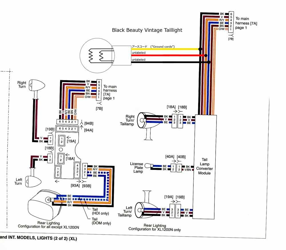
- Components: Turn signal wiring diagrams show the various components involved in the turn signal system, including the turn signal switch, turn signal lights, flasher unit, and electrical wires.
- Connections: The diagram outlines the specific connections between the components, indicating which wires connect to which terminals and in what sequence.
- Wire colors: Diagrams use color-coded wires to simplify identification and ensure correct connections.
- Grounding: Proper grounding is essential for turn signals to function correctly, and the diagram indicates the grounding points.
- Flasher unit: The flasher unit controls the blinking rate of the turn signals, and the diagram shows how it connects to the other components.
- Switch operation: The diagram illustrates how the turn signal switch operates and how it activates the left or right turn signals.
- Troubleshooting: Wiring diagrams are invaluable for troubleshooting turn signal issues, helping identify faulty connections or components.
- Customization: For riders who want to customize their turn signals, the diagram provides a starting point for understanding the electrical system and making modifications.
- Safety: Correctly wired turn signals are essential for rider safety, ensuring that other vehicles and pedestrians can clearly see the rider’s intentions.
These aspects collectively provide a comprehensive understanding of Harley Davidson turn signal wiring diagrams. They are essential for anyone working on the electrical system of a Harley Davidson motorcycle, ensuring safe and reliable operation of turn signals.
Components
Within the context of “Harley Davidson Turn Signal Wiring Diagram”, understanding the individual components involved is crucial for proper installation, maintenance, and troubleshooting. The wiring diagram provides a visual representation of these components and their interconnections, ensuring a clear understanding of the turn signal system’s operation.
- Turn signal switch: The switch mounted on the handlebars controls the activation and selection of left or right turn signals.
- Turn signal lights: These lights, located at the front and rear of the motorcycle, illuminate to indicate the rider’s turning intention.
- Flasher unit: This electronic device regulates the blinking rate of the turn signals, ensuring they flash at a consistent and noticeable pace.
- Electrical wires: Color-coded wires connect the various components, carrying electrical signals and power throughout the turn signal system.
These components collectively form the turn signal system on a Harley Davidson motorcycle. By understanding their roles and connections through the wiring diagram, individuals can effectively diagnose and resolve any issues, ensuring the turn signals function correctly and enhance safety on the road.
Connections
Within the context of “Harley Davidson Turn Signal Wiring Diagram”, understanding the connections between components is fundamental for proper installation, maintenance, and troubleshooting. The wiring diagram provides a visual representation of these connections, including the specific wires involved and the sequence in which they connect.
- Terminal identification: The diagram clearly indicates the terminals on each component where the wires should be connected, ensuring proper electrical flow and functionality.
- Color-coded wires: Harley Davidson wiring diagrams use color-coded wires to simplify identification and prevent errors during installation. The diagram matches the wire colors to the corresponding terminals, making it easier to trace connections and avoid mix-ups.
- Grounding: Proper grounding is crucial for the turn signal system to function correctly. The diagram specifies the grounding points, ensuring that the electrical circuit is complete and the turn signals operate as intended.
- Flasher unit connections: The flasher unit controls the blinking rate of the turn signals. The wiring diagram shows how the flasher unit connects to the other components, ensuring that it receives the necessary power and signals to operate correctly.
Overall, understanding the connections outlined in the Harley Davidson turn signal wiring diagram is essential for accurate installation, maintenance, and troubleshooting. By following the diagram’s guidance, individuals can ensure that the turn signals function properly, enhancing safety on the road.
Wire colors
In the context of Harley Davidson turn signal wiring diagrams, color-coded wires play a critical role in simplifying the identification and ensuring the correct connections of electrical components. The use of color-coded wires is an essential aspect of these diagrams, as it streamlines the installation, maintenance, and troubleshooting processes.
Harley Davidson turn signal wiring diagrams employ a standardized color-coding system, where each wire color corresponds to a specific function or component. This standardized approach allows for easy identification of wires, even for individuals who may not have extensive electrical experience. By following the color-coded wires outlined in the diagram, users can quickly and accurately connect the turn signal components, reducing the risk of errors and ensuring proper functionality.
For instance, in a Harley Davidson turn signal wiring diagram, the black wire typically represents the ground wire, while the green wire is often used for the right turn signal and the yellow wire for the left turn signal. This consistent color-coding scheme simplifies the wiring process, making it easier for individuals to trace connections and verify the correct installation of the turn signal system.
Understanding the relationship between wire colors and their corresponding functions is crucial for accurate electrical connections. By adhering to the color-coding guidelines outlined in the Harley Davidson turn signal wiring diagram, individuals can ensure that the turn signals operate correctly, enhancing their visibility and safety on the road.
Grounding
In the context of Harley Davidson turn signal wiring diagrams, proper grounding is crucial for ensuring the correct functionality of turn signals. A well-grounded electrical system provides a complete circuit, allowing current to flow properly and preventing malfunctions. The wiring diagram plays a vital role in identifying the designated grounding points, which are essential for establishing a secure electrical connection.
- Frame Ground: The motorcycle’s frame often serves as the primary grounding point. The wiring diagram indicates the specific locations where the turn signal wires should be connected to the frame, creating a direct path for current to flow back to the battery.
- Dedicated Grounding Wires: In some cases, the wiring diagram may specify dedicated grounding wires that connect the turn signal components directly to the battery’s negative terminal. These wires provide an alternative grounding path, ensuring a reliable connection even if the frame ground is compromised.
- Grounding Block: The wiring diagram may also include a grounding block, which is a central point where multiple electrical components are grounded. This block simplifies the grounding process and reduces the number of individual connections to the frame or battery.
- Testing Ground Connections: The wiring diagram provides guidance on testing the integrity of ground connections. It outlines the steps for using a multimeter to measure continuity between the grounding points and the battery’s negative terminal, ensuring that the electrical circuit is complete.
Understanding and following the grounding guidelines outlined in the Harley Davidson turn signal wiring diagram is essential for ensuring the proper operation of turn signals. By establishing secure and reliable grounding connections, riders can ensure that their turn signals function correctly, enhancing their safety and visibility on the road.
Flasher unit
Within the context of Harley Davidson turn signal wiring diagrams, the flasher unit holds critical importance, and its integration is meticulously detailed in these diagrams. The flasher unit serves as the regulating force behind the turn signals’ blinking rate, ensuring they flash at a consistent and noticeable pace. Understanding its connection to other components through the wiring diagram is vital for proper turn signal functionality and enhanced rider safety.
The wiring diagram provides a visual representation of how the flasher unit interacts with the turn signal switch, turn signal lights, and electrical wires. By following the diagram’s guidance, individuals can accurately connect the flasher unit to the corresponding terminals, ensuring that it receives the necessary power and signals to operate correctly.
A practical example of the flasher unit’s significance in a Harley Davidson turn signal wiring diagram can be observed in troubleshooting scenarios. If the turn signals are not blinking or are blinking too rapidly or slowly, the flasher unit may be the culprit. By referring to the wiring diagram, individuals can identify the flasher unit’s location, inspect its connections, and determine if it requires replacement.
Furthermore, understanding the flasher unit’s connection within the wiring diagram allows for customization and modifications to the turn signal system. For instance, riders may want to install a different flasher unit to alter the blinking rate or add additional turn signal lights. The wiring diagram serves as a roadmap for these modifications, guiding individuals in making the necessary electrical connections.
In summary, the flasher unit plays a pivotal role within Harley Davidson turn signal wiring diagrams. By understanding its connection to other components, individuals can ensure the proper functioning of turn signals, troubleshoot issues effectively, and customize the system to meet their specific needs. This understanding enhances rider safety and contributes to the overall reliability of the motorcycle’s electrical system.
Switch operation
Within the context of “Harley Davidson Turn Signal Wiring Diagram”, understanding the operation of the turn signal switch is crucial as it plays a pivotal role in initiating and controlling the turn signal system. The wiring diagram provides a visual representation of the switch’s operation, outlining the connections and mechanism that activate the left or right turn signals.
The turn signal switch is typically mounted on the handlebars of the motorcycle, within easy reach of the rider. When the rider intends to make a turn, they operate the switch to activate the corresponding turn signal. The wiring diagram illustrates the internal workings of the switch, showing how it completes the electrical circuit and sends signals to the flasher unit.
A practical example of the importance of understanding switch operation can be observed in troubleshooting scenarios. If the turn signals are not functioning correctly, the wiring diagram can guide the individual in identifying potential issues with the switch. By referring to the diagram, they can trace the electrical connections and verify if the switch is sending the correct signals.
Furthermore, a comprehensive understanding of the turn signal switch’s operation enables riders to customize their turn signal system. For instance, some riders may want to install a different type of switch with additional features or a different actuation mechanism. The wiring diagram serves as a reference for these modifications, guiding individuals in making the necessary electrical connections.
In summary, the “Switch operation” section of the Harley Davidson Turn Signal Wiring Diagram provides critical information about the operation of the turn signal switch. Understanding this section allows individuals to troubleshoot issues, make modifications, and gain a deeper understanding of the motorcycle’s electrical system. This knowledge enhances rider safety and contributes to the reliability of the turn signal system.
Troubleshooting
Within the context of Harley Davidson turn signal wiring diagrams, troubleshooting plays a crucial role in maintaining the proper functioning of the turn signal system. These diagrams provide a comprehensive visual representation of the electrical connections, allowing individuals to identify and resolve issues effectively.
When turn signals malfunction, whether due to faulty connections or defective components, the wiring diagram serves as a valuable diagnostic tool. By tracing the electrical pathways outlined in the diagram, individuals can pinpoint the source of the problem and take appropriate corrective actions.
One common issue that can be diagnosed using a Harley Davidson turn signal wiring diagram is a faulty connection. Loose or corroded connections can disrupt the flow of electricity, causing turn signals to malfunction or operate erratically. The wiring diagram helps identify the specific connection points that need to be inspected and tightened or cleaned to restore proper functionality.
Another scenario where the wiring diagram proves invaluable is when troubleshooting a defective component. By following the electrical connections shown in the diagram, individuals can isolate the faulty component and determine whether it needs to be repaired or replaced.
Understanding how to troubleshoot using a Harley Davidson turn signal wiring diagram empowers individuals to maintain the reliability of their turn signal system. By promptly identifying and resolving issues, riders can ensure that their turn signals are always in good working order, enhancing their safety on the road.
Customization
The Harley Davidson Turn Signal Wiring Diagram not only aids in troubleshooting and repair but also serves as a valuable asset for riders who seek to customize their turn signals. By providing a comprehensive overview of the electrical system, the diagram empowers individuals to make informed modifications that enhance the functionality and aesthetics of their motorcycles.
One common customization involves upgrading to LED turn signals. These aftermarket turn signals offer several advantages, including improved visibility, reduced power consumption, and a more modern appearance. The wiring diagram guides riders in understanding the electrical requirements for LED turn signals, ensuring compatibility and proper operation.
Another popular customization is the integration of additional turn signals. Riders may choose to add front or rear turn signals to increase their visibility on the road. The wiring diagram provides insights into the electrical connections needed to seamlessly incorporate these additional turn signals into the existing system.
Furthermore, the wiring diagram allows riders to explore creative modifications, such as custom turn signal switch configurations or the installation of turn signal buzzers. By understanding the electrical pathways, riders can tailor their turn signal system to meet their specific needs and preferences.
In summary, the customization aspect of the Harley Davidson Turn Signal Wiring Diagram is a valuable resource for riders who seek to enhance the functionality and aesthetics of their turn signals. By providing a detailed representation of the electrical system, the diagram empowers individuals to make informed modifications, ensuring safe and reliable operation while adding a personal touch to their motorcycles.
Safety
Within the context of Harley Davidson Turn Signal Wiring Diagrams, the paramount importance of correctly wired turn signals cannot be overstated. They play a critical role in ensuring rider safety by enabling effective communication of the rider’s intentions to other vehicles and pedestrians on the road.
Incorrectly wired turn signals or those that malfunction can lead to confusion and potentially dangerous situations. For example, if a turn signal is not functioning properly, it may not illuminate or may provide an incorrect indication, misleading other road users about the rider’s intended direction of travel. This can increase the risk of accidents, especially at intersections or when changing lanes.
Conversely, when turn signals are correctly wired and in good working order, they provide a clear and unambiguous indication of the rider’s intentions, making it easier for other vehicles and pedestrians to anticipate the rider’s actions. This enhanced visibility and communication help prevent accidents and promote safer riding conditions for all.
The Harley Davidson Turn Signal Wiring Diagram serves as an essential tool for ensuring the proper wiring and operation of turn signals. By following the detailed instructions and adhering to the specified electrical connections outlined in the diagram, individuals can confidently install, maintain, and troubleshoot their turn signal systems, contributing to their overall safety on the road.


Related Posts


