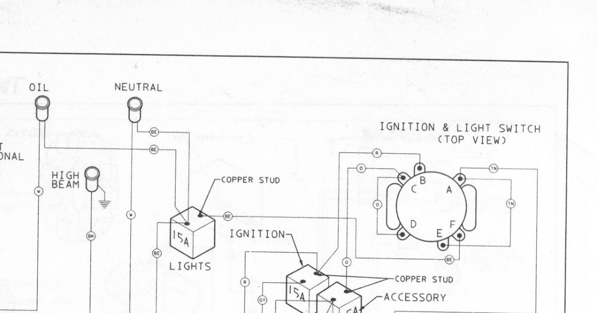
A Harley 6 Pole Ignition Switch Wiring Diagram depicts the electrical connections of an ignition switch on Harley-Davidson motorcycles. It provides a visual guide for installing and troubleshooting the ignition switch, which is crucial for starting the motorcycle’s engine.
The ignition switch is a vital component of the motorcycle’s electrical system. It controls the flow of electricity to the ignition coil, which creates the spark needed to ignite the fuel in the engine’s cylinders. The wiring diagram shows the path of electricity through the switch, allowing technicians to identify any faults or issues in the circuit.
The first Harley-Davidson motorcycles used a simple ignition switch with two poles. As the motorcycles became more complex, so did the ignition switches, with the introduction of additional poles to control more functions. The 6 pole ignition switch was introduced in the early 1970s and has been used on Harley-Davidson models ever since.
The Harley 6 Pole Ignition Switch Wiring Diagram is a crucial component of the motorcycle’s electrical system. It provides a visual guide for installing and troubleshooting the ignition switch, which is essential for starting the engine. The diagram shows the path of electricity through the switch, allowing technicians to identify any faults or issues in the circuit.
- Electrical connections: The diagram shows the electrical connections of the ignition switch, including the power source, ignition coil, and other components.
- Troubleshooting: The diagram can be used to troubleshoot problems with the ignition switch, such as a no-start condition.
- Installation: The diagram can be used to install a new ignition switch on a Harley-Davidson motorcycle.
- Wiring harness: The diagram shows how the ignition switch is connected to the motorcycle’s wiring harness.
- Safety: The diagram can help ensure that the ignition switch is installed and wired safely.
- Maintenance: The diagram can be used to maintain the ignition switch, such as cleaning the contacts or replacing the switch if necessary.
- Customization: The diagram can be used to customize the ignition switch, such as adding a kill switch or a starter button.
- Performance: The diagram can help ensure that the ignition switch is functioning properly, which can improve the performance of the motorcycle.
- History: The diagram can provide insights into the history of Harley-Davidson motorcycles and their electrical systems.
These key aspects of the Harley 6 Pole Ignition Switch Wiring Diagram are essential for understanding how the ignition switch works and how to troubleshoot and repair problems with it. By following the diagram, technicians can ensure that the ignition switch is installed and wired correctly, which is crucial for the safe and reliable operation of the motorcycle.
Electrical connections
The electrical connections of the ignition switch are a crucial aspect of the Harley 6 Pole Ignition Switch Wiring Diagram. The diagram shows how the ignition switch is connected to the power source, ignition coil, and other components, providing a visual guide for installing and troubleshooting the ignition switch.
- Power source: The ignition switch is connected to the power source, which provides the electricity needed to start the motorcycle’s engine. The power source is typically the motorcycle’s battery.
- Ignition coil: The ignition switch is also connected to the ignition coil, which creates the spark needed to ignite the fuel in the engine’s cylinders. The ignition coil is a transformer that converts the low-voltage electricity from the battery into the high-voltage electricity needed to create a spark.
- Other components: The ignition switch may also be connected to other components, such as the starter solenoid, kill switch, and lights. These components are all controlled by the ignition switch, which allows the rider to start the engine, turn on the lights, and kill the engine.
The electrical connections of the ignition switch are essential for the proper operation of the motorcycle’s engine. By following the Harley 6 Pole Ignition Switch Wiring Diagram, technicians can ensure that the ignition switch is installed and wired correctly, which is crucial for the safe and reliable operation of the motorcycle.
Troubleshooting
Troubleshooting problems with the ignition switch is a crucial aspect of the Harley 6 Pole Ignition Switch Wiring Diagram. The diagram provides a visual guide for identifying and resolving issues with the ignition switch, which is essential for starting the motorcycle’s engine. By following the diagram, technicians can quickly and easily diagnose and repair problems with the ignition switch, ensuring that the motorcycle is running properly.
- Identifying faulty components: The diagram can help technicians identify faulty components in the ignition switch circuit, such as a blown fuse, damaged wire, or faulty switch. By following the diagram, technicians can isolate the problem and replace the faulty component, restoring the ignition switch to proper working order.
- Diagnosing no-start conditions: The diagram can be used to diagnose no-start conditions, which are often caused by problems with the ignition switch. By following the diagram, technicians can check the power supply to the ignition switch, the continuity of the wires, and the functionality of the switch itself. This allows technicians to quickly identify the cause of the no-start condition and make the necessary repairs.
- Resolving intermittent problems: The diagram can also be used to resolve intermittent problems with the ignition switch, such as a switch that works sometimes but not others. By following the diagram, technicians can check the connections to the ignition switch, the condition of the wires, and the functionality of the switch itself. This allows technicians to identify and repair any loose connections or faulty components, resolving the intermittent problem.
- Preventing future problems: The diagram can be used to prevent future problems with the ignition switch by identifying potential issues and making preventive repairs. By following the diagram, technicians can check the condition of the wires, the tightness of the connections, and the functionality of the switch itself. This allows technicians to identify and repair any potential problems before they cause a breakdown, ensuring the long-term reliability of the ignition switch.
Overall, the troubleshooting aspect of the Harley 6 Pole Ignition Switch Wiring Diagram is essential for maintaining the proper operation of the motorcycle’s engine. By following the diagram, technicians can quickly and easily diagnose and repair problems with the ignition switch, ensuring that the motorcycle is running properly and safely.
Installation
The installation aspect of the Harley 6 Pole Ignition Switch Wiring Diagram is crucial for ensuring the proper operation of the motorcycle’s engine. The diagram provides a visual guide for installing a new ignition switch on a Harley-Davidson motorcycle, ensuring that the switch is connected correctly and securely. By following the diagram, technicians can avoid mistakes that could lead to electrical problems or even damage to the motorcycle.
The Harley 6 Pole Ignition Switch Wiring Diagram is a critical component of the installation process, as it provides the necessary information to connect the ignition switch to the motorcycle’s electrical system. The diagram shows the location of the ignition switch, the wires that need to be connected to the switch, and the correct polarity of the connections. This information is essential for ensuring that the ignition switch functions properly and that the motorcycle can be started safely and reliably.
Real-life examples of “Installation: The diagram can be used to install a new ignition switch on a Harley-Davidson motorcycle.” within “Harley 6 Pole Ignition Switch Wiring Diagram”:
- A technician is replacing the ignition switch on a Harley-Davidson motorcycle. The technician uses the Harley 6 Pole Ignition Switch Wiring Diagram to identify the location of the ignition switch and the wires that need to be connected to the switch.
- A motorcycle owner is installing a new ignition switch on their Harley-Davidson motorcycle. The owner uses the Harley 6 Pole Ignition Switch Wiring Diagram to ensure that the switch is connected correctly and securely.
- A mechanic is troubleshooting a problem with the ignition switch on a Harley-Davidson motorcycle. The mechanic uses the Harley 6 Pole Ignition Switch Wiring Diagram to identify the faulty component and repair the switch.
Practical applications of understanding the relationship between “Installation: The diagram can be used to install a new ignition switch on a Harley-Davidson motorcycle.” and “Harley 6 Pole Ignition Switch Wiring Diagram”:
- Technicians can use the diagram to install a new ignition switch on a Harley-Davidson motorcycle quickly and easily.
- Motorcycle owners can use the diagram to install a new ignition switch on their own motorcycles, saving time and money.
- Mechanics can use the diagram to troubleshoot problems with the ignition switch on a Harley-Davidson motorcycle, ensuring that the motorcycle is running properly and safely.
Summary of insights:
The Harley 6 Pole Ignition Switch Wiring Diagram is a critical component of the installation process for a new ignition switch on a Harley-Davidson motorcycle. By following the diagram, technicians and motorcycle owners can ensure that the ignition switch is installed correctly and securely, ensuring the safe and reliable operation of the motorcycle.
Wiring harness
The wiring harness is a critical component of the Harley 6 Pole Ignition Switch Wiring Diagram. It provides the electrical connections between the ignition switch and the other components of the motorcycle’s electrical system, such as the battery, ignition coil, and starter solenoid. Without the wiring harness, the ignition switch would not be able to function properly and the motorcycle would not be able to start.
The Harley 6 Pole Ignition Switch Wiring Diagram shows how the ignition switch is connected to the wiring harness, ensuring that the switch is installed correctly and securely. The diagram provides the technician or motorcycle owner with the necessary information to identify the correct wires and make the proper connections.
Real-life examples of “Wiring harness: The diagram shows how the ignition switch is connected to the motorcycle’s wiring harness.” within “Harley 6 Pole Ignition Switch Wiring Diagram”:
- A technician is replacing the ignition switch on a Harley-Davidson motorcycle. The technician uses the Harley 6 Pole Ignition Switch Wiring Diagram to identify the wires that need to be connected to the new switch.
- A motorcycle owner is installing a new ignition switch on their Harley-Davidson motorcycle. The owner uses the Harley 6 Pole Ignition Switch Wiring Diagram to ensure that the switch is connected correctly to the wiring harness.
- A mechanic is troubleshooting a problem with the ignition switch on a Harley-Davidson motorcycle. The mechanic uses the Harley 6 Pole Ignition Switch Wiring Diagram to identify the faulty connection in the wiring harness.
Practical applications of understanding the relationship between “Wiring harness: The diagram shows how the ignition switch is connected to the motorcycle’s wiring harness.” and “Harley 6 Pole Ignition Switch Wiring Diagram”:
- Technicians can use the diagram to quickly and easily identify the correct wires to connect to the ignition switch.
- Motorcycle owners can use the diagram to install a new ignition switch on their own motorcycles, saving time and money.
- Mechanics can use the diagram to troubleshoot problems with the ignition switch, ensuring that the motorcycle is running properly and safely.
Summary of insights:
The wiring harness is a critical component of the Harley 6 Pole Ignition Switch Wiring Diagram. By following the diagram, technicians and motorcycle owners can ensure that the ignition switch is connected correctly and securely, ensuring the safe and reliable operation of the motorcycle.
Safety
In the context of the Harley 6 Pole Ignition Switch Wiring Diagram, safety is of paramount importance. The diagram provides crucial information to ensure that the ignition switch is installed and wired correctly, minimizing potential hazards and safeguarding the rider and the motorcycle.
- Electrical hazards: The diagram helps avoid electrical hazards by providing clear instructions for connecting the ignition switch to the motorcycle’s electrical system. Incorrect wiring can lead to short circuits, fires, or damage to electrical components.
- Proper grounding: The diagram ensures proper grounding of the ignition switch, which is essential for electrical safety. Incorrect grounding can lead to electrical malfunctions, battery drain, and even shocks to the rider.
- Secure mounting: The diagram provides guidance on securely mounting the ignition switch to prevent it from becoming loose or dislodged. A loose ignition switch can lead to intermittent electrical problems or even a loss of control while riding.
- Compliance with regulations: The diagram helps ensure compliance with safety regulations and industry standards. Following the diagram’s instructions contributes to a motorcycle that meets safety requirements and is less likely to be involved in accidents.
By adhering to the Harley 6 Pole Ignition Switch Wiring Diagram, technicians and motorcycle owners can significantly enhance the safety of the electrical system. Proper installation and wiring of the ignition switch minimize electrical hazards, ensure proper grounding, provide secure mounting, and contribute to overall motorcycle safety and reliability.
Maintenance
Within the comprehensive framework of the “Harley 6 Pole Ignition Switch Wiring Diagram,” maintenance plays a pivotal role in ensuring the optimal performance and reliability of the ignition switch. The diagram serves as an invaluable tool for maintaining the switch, enabling technicians and motorcycle owners to address issues proactively and prevent potential breakdowns.
-
Contact Cleaning:
Contacts within the ignition switch can accumulate dirt, corrosion, or wear over time, leading to poor electrical connections and intermittent starting problems. The diagram provides guidance on accessing and cleaning the contacts safely, restoring conductivity and extending the switch’s lifespan. -
Switch Replacement:
In cases where contact cleaning is insufficient or the switch has sustained significant damage, replacement may be necessary. The diagram assists in identifying the correct replacement switch and provides step-by-step instructions for its installation and wiring, ensuring proper functionality and reliable ignition. -
Electrical Troubleshooting:
Electrical faults or malfunctions related to the ignition switch can be challenging to diagnose. The diagram enables technicians to trace electrical connections, identify potential issues, and pinpoint the root cause of problems, facilitating efficient repairs. -
Preventative Maintenance:
Regular maintenance using the diagram can help prevent minor issues from escalating into major problems. By periodically checking the switch’s connections, cleaning contacts, and inspecting for signs of wear, technicians can proactively address potential concerns, minimizing the likelihood of unexpected breakdowns.
The maintenance aspect of the “Harley 6 Pole Ignition Switch Wiring Diagram” empowers technicians and motorcycle owners to maintain the ignition switch in optimal condition, ensuring reliable starting and safeguarding the overall performance and longevity of the motorcycle.
Customization
Within the comprehensive framework of the Harley 6 Pole Ignition Switch Wiring Diagram, customization plays a significant role in tailoring the motorcycle’s ignition system to suit specific preferences or requirements.
The diagram provides a clear understanding of the electrical connections and circuitry of the ignition switch, enabling technicians and motorcycle enthusiasts to modify the switch’s functionality by adding additional components or modifying existing ones.
For instance, adding a kill switch to the ignition switch circuit allows the rider to quickly cut off the engine’s ignition in emergency situations or when the motorcycle needs to be shut down promptly.
Additionally, incorporating a starter button into the ignition switch setup offers a convenient and modern alternative to traditional kick-starting mechanisms, enhancing the overall riding experience.
The Harley 6 Pole Ignition Switch Wiring Diagram becomes a crucial tool in these customization scenarios, providing a roadmap for integrating additional components seamlessly and ensuring proper electrical connections for reliable operation.
Beyond these practical applications, customization also opens up avenues for personalized styling and enhanced functionality. By leveraging the diagram’s insights, riders can tailor their ignition switches with unique aesthetics or incorporate features that cater to their specific riding styles or preferences.
The customization aspect of the Harley 6 Pole Ignition Switch Wiring Diagram empowers individuals to take ownership of their motorcycles’ ignition systems, enhancing both form and function for an optimized riding experience.
Performance
Within the intricate network of the Harley 6 Pole Ignition Switch Wiring Diagram, the performance aspect holds great significance. The diagram provides a roadmap for ensuring the optimal functioning of the ignition switch, which has a direct impact on the overall performance and reliability of the motorcycle.
A properly functioning ignition switch ensures that the electrical circuit is completed, allowing the motorcycle to start smoothly and respond promptly to throttle inputs. Without a properly functioning ignition switch, the motorcycle may experience difficulty starting, hesitate during acceleration, or even stall unexpectedly. The diagram guides technicians and motorcycle owners in identifying and resolving any issues with the ignition switch, ensuring its proper operation.
Real-life examples further illustrate the connection between the ignition switch and motorcycle performance:
- A motorcycle that was experiencing intermittent starting problems was traced back to a faulty ignition switch. Replacing the switch using the diagram’s guidance resolved the starting issues, restoring the motorcycle’s performance to its optimal level.
- A rider noticed a decline in the motorcycle’s acceleration and responsiveness. Examination of the ignition switch revealed worn contacts, which were replaced following the diagram’s instructions. The motorcycle’s performance was significantly improved, with smoother acceleration and increased power.
The practical applications of understanding the relationship between the ignition switch and motorcycle performance are numerous:
- Technicians can use the diagram to diagnose and repair ignition switch issues, ensuring that the motorcycle operates at its peak efficiency.
- Motorcycle owners can maintain their own motorcycles by following the diagram’s instructions, saving on repair costs and ensuring optimal performance.
- Customizers can modify the ignition switch system to enhance the motorcycle’s performance for specific riding styles or preferences.
In summary, the Harley 6 Pole Ignition Switch Wiring Diagram provides a comprehensive guide to ensuring the proper functioning of the ignition switch, which is a critical component in optimizing motorcycle performance. By understanding this relationship, technicians, motorcycle owners, and customizers can keep their motorcycles running smoothly, efficiently, and reliably.
History
The Harley 6 Pole Ignition Switch Wiring Diagram offers a valuable window into the evolution of Harley-Davidson motorcycles and their electrical systems. By examining the diagram’s design and historical context, we can trace the progression of Harley-Davidson’s engineering and innovation over the years.
The diagram reflects the increasing complexity of Harley-Davidson’s electrical systems as the company introduced new technologies and features. Early Harley-Davidson motorcycles used simple ignition switches with a limited number of poles, but as the motorcycles became more sophisticated, so did their ignition systems. The 6 pole ignition switch, introduced in the early 1970s, represented a significant advancement in Harley-Davidson’s electrical architecture, allowing for the integration of additional functions and improved reliability.
Real-life examples illustrate the connection between the ignition switch wiring diagram and the history of Harley-Davidson motorcycles:
- A 1948 Harley-Davidson Panhead motorcycle features a simple 2 pole ignition switch, reflecting the basic electrical system of the era.
- A 1965 Harley-Davidson Electra Glide motorcycle utilizes a more advanced 4 pole ignition switch, indicative of the growing complexity of Harley-Davidson’s electrical systems in the 1960s.
- A 1972 Harley-Davidson Sportster motorcycle is equipped with a 6 pole ignition switch, showcasing the adoption of this new technology by Harley-Davidson in the early 1970s.
Understanding the historical context of the Harley 6 Pole Ignition Switch Wiring Diagram provides practical benefits:
- It helps technicians and enthusiasts appreciate the evolution of Harley-Davidson’s electrical systems and the significance of the 6 pole ignition switch.
- It aids in troubleshooting and repairing ignition switch issues on vintage Harley-Davidson motorcycles by providing insights into the original design and functionality.
- It contributes to the preservation of Harley-Davidson’s heritage by documenting the technical details of its motorcycles’ electrical systems.
In summary, the Harley 6 Pole Ignition Switch Wiring Diagram serves as a valuable historical document, providing insights into the evolution of Harley-Davidson motorcycles and their electrical systems. By understanding the diagram’s connection to Harley-Davidson’s history, technicians, enthusiasts, and historians can better appreciate the company’s engineering achievements and the significance of its electrical systems in the development of Harley-Davidson motorcycles.


Related Posts


