A “Hand Off Auto Switch Wiring Diagram” outlines the electrical connections for a switch that allows manual control of a device or system from a remote location. For example, a typical home lighting circuit includes a wall switch that controls the lights. Adding a hand-off auto switch to this circuit would enable the lights to be turned on and off remotely using a wireless remote control or other automation system.
Hand-off auto switches provide convenience and flexibility in various applications. They enable remote control of lights, fans, appliances, and other electrical devices, enhancing accessibility and reducing the need for physical interaction. Historically, the development of solid-state electronics and wireless communication technologies has significantly advanced the design and functionality of hand-off auto switches, leading to more reliable and user-friendly systems.
This article will delve into the details of hand-off auto switch wiring diagrams, including common wiring configurations, safety considerations, and troubleshooting tips. By understanding these aspects, electricians and DIY enthusiasts can effectively install and maintain hand-off auto switches for various electrical applications.
Understanding the essential aspects of a “Hand Off Auto Switch Wiring Diagram” is crucial for proper installation, maintenance, and troubleshooting. These aspects encompass various dimensions related to the wiring diagram, including its components, connections, and functionality.
- Circuit Design: Outlines the electrical circuit’s layout and component arrangement.
- Switch Type: Specifies the type of switch used, such as a single-pole, double-throw (SPDT) or double-pole, double-throw (DPDT) switch.
- Wire Gauge: Indicates the appropriate wire size for the circuit, ensuring proper current flow.
- Connection Points: Identifies the specific terminals on the switch and other components where wires should be connected.
- Electrical Codes: Adherence to electrical codes ensures safety and compliance.
- Grounding: Proper grounding protects against electrical hazards.
- Troubleshooting Guide: Provides steps to diagnose and resolve common issues.
- Component Specifications: Details the technical specifications of the switch and other components.
- Safety Precautions: Highlights essential safety measures to follow during installation and maintenance.
These aspects are interconnected and play a vital role in the effective functioning of a hand-off auto switch wiring diagram. Understanding these aspects enables electricians and DIY enthusiasts to create safe and reliable electrical installations. For instance, proper circuit design ensures efficient current flow, while adherence to electrical codes minimizes the risk of electrical fires. Troubleshooting guides provide valuable assistance in diagnosing and resolving issues, reducing downtime and ensuring uninterrupted operation.
Circuit Design
Circuit design serves as the foundation for a well-executed “Hand Off Auto Switch Wiring Diagram”. It dictates the placement and interconnection of electrical components, ensuring efficient current flow and proper system operation. The circuit design specifies wire routing, component locations, and connection points, providing a roadmap for assembling the wiring diagram. Without a well-defined circuit design, the wiring diagram would lack structure and could lead to errors or malfunctions.
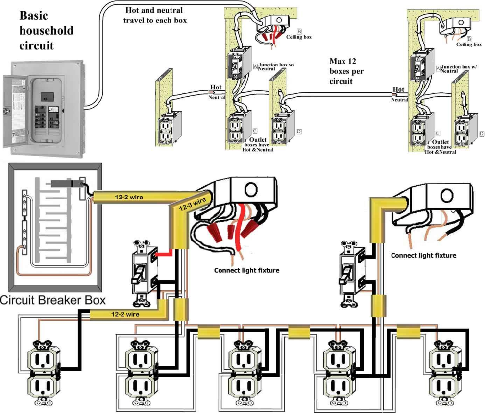
Real-life examples abound where circuit design plays a crucial role in hand-off auto switch wiring diagrams. In a residential setting, a lighting circuit controlled by a hand-off auto switch requires careful planning of wire routing and component placement to ensure safe and functional operation. Industrial applications often involve complex circuits with multiple hand-off auto switches controlling various machinery or processes. Proper circuit design is essential in these scenarios to prevent interference, ensure proper sequencing, and maintain reliable system performance.
Understanding the connection between circuit design and hand-off auto switch wiring diagrams empowers electricians, engineers, and DIY enthusiasts to create safe, efficient, and reliable electrical systems. By adhering to electrical codes and best practices during circuit design, they can minimize the risk of electrical hazards, ensure optimal performance, and facilitate troubleshooting if issues arise. Furthermore, a well-designed circuit can simplify future modifications or expansions, making the system more adaptable to changing needs.
Switch Type
The type of switch used in a “Hand Off Auto Switch Wiring Diagram” significantly impacts the circuit’s functionality and application. Single-pole, double-throw (SPDT) switches are commonly employed to control a single circuit, allowing current to flow in either direction. Double-pole, double-throw (DPDT) switches, on the other hand, can control two separate circuits simultaneously, providing greater flexibility in circuit design.
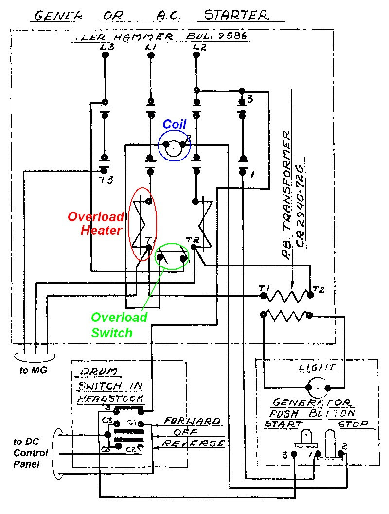
The choice between SPDT and DPDT switches depends on the specific requirements of the application. For instance, in a simple lighting circuit, an SPDT switch would suffice to turn the light on or off. However, if the circuit involves controlling multiple lights or appliances independently, a DPDT switch would be necessary. DPDT switches are also commonly used in motor control circuits, where they can reverse the direction of the motor’s rotation.
Understanding the relationship between switch type and wiring diagram is crucial for proper circuit design and implementation. By selecting the appropriate switch type based on the circuit’s requirements, electricians and DIY enthusiasts can ensure safe, efficient, and reliable operation of their electrical systems. This understanding is particularly important in complex circuits involving multiple switches and devices, where proper switch selection is essential to avoid malfunctions or hazards.
Wire Gauge
In a “Hand Off Auto Switch Wiring Diagram”, the wire gauge, which indicates the appropriate wire size for the circuit, plays a crucial role in ensuring proper current flow and safe operation. The relationship between wire gauge and the wiring diagram is pivotal because undersized wires can lead to excessive current draw, overheating, and potential fire hazards. Conversely, oversized wires, while less common, can result in unnecessary material costs and potential installation challenges.
Real-life examples underscore the importance of proper wire gauge selection. In residential lighting circuits, for instance, using wires with insufficient gauge for the load can cause the wires to overheat and pose a fire risk. Similarly, in industrial settings where high-power machinery is involved, employing wires with inadequate gauge can lead to equipment damage or electrical accidents. By adhering to recommended wire gauge specifications in the wiring diagram, electricians can ensure the safe and reliable operation of electrical systems.
Understanding the connection between wire gauge and hand-off auto switch wiring diagrams empowers individuals to make informed decisions during electrical installations and modifications. Proper wire gauge selection contributes to efficient energy distribution, prevents electrical hazards, and ensures the longevity of electrical components. By considering factors such as circuit load, voltage, and wire routing, electricians and DIY enthusiasts can create safe and functional electrical systems that meet the specific requirements of their applications.
Connection Points
In a “Hand Off Auto Switch Wiring Diagram”, connection points play a pivotal role in establishing proper electrical connections between the switch, other components, and the power source. These connection points are carefully identified on the diagram, specifying the specific terminals where wires should be connected to ensure proper circuit operation. Without clearly defined connection points, the wiring diagram would lack precision, leading to potential errors and malfunctions.
The importance of connection points in hand-off auto switch wiring diagrams is evident in real-life examples. Consider a residential lighting circuit controlled by a hand-off auto switch. Precise identification of connection points on the switch, light fixture, and wiring ensures that the switch can effectively control the light’s power supply. Incorrect connections could result in the light malfunctioning or even posing electrical hazards. In industrial settings, where complex machinery is controlled by hand-off auto switches, accurate connection points are critical for maintaining proper sequencing and preventing electrical accidents.
Understanding the relationship between connection points and hand-off auto switch wiring diagrams empowers individuals to perform safe and reliable electrical installations and modifications. By adhering to the specified connection points, electricians and DIY enthusiasts can ensure that wires are connected to the correct terminals, avoiding potential short circuits, damage to components, or electrical fires. This understanding is especially valuable when troubleshooting electrical issues, as it provides a systematic approach to identifying and resolving connection-related problems.
In summary, connection points serve as the foundation for establishing proper electrical connections in hand-off auto switch wiring diagrams. Their precise identification ensures efficient current flow, prevents malfunctions, and enhances electrical safety. Understanding the connection between connection points and wiring diagrams empowers individuals to create and maintain reliable electrical systems, contributing to the safe and efficient operation of various electrical applications.
Electrical Codes
In the context of “Hand Off Auto Switch Wiring Diagrams,” adherence to electrical codes is paramount for ensuring safety and compliance. Electrical codes establish a set of regulations and guidelines that govern the installation, maintenance, and inspection of electrical systems. Complying with these codes helps prevent electrical hazards, fires, and accidents, while also ensuring that electrical systems operate efficiently and reliably.
- Safeguards: Electrical codes incorporate safety measures to protect individuals from electrical shocks, electrocution, and fires. These measures include requirements for proper grounding, insulation, and overcurrent protection devices.
- Compliance: Adhering to electrical codes is essential for obtaining permits, passing inspections, and meeting insurance requirements. Compliance also demonstrates a commitment to maintaining safe and up-to-code electrical installations.
- Reliability: Electrical codes promote the use of high-quality materials and proper installation techniques, enhancing the reliability and lifespan of electrical systems. By following these codes, electricians can minimize the risk of system failures and costly repairs.
- Consistency: Electrical codes provide a standardized set of rules and regulations, ensuring consistency in electrical installations across different regions and projects. This consistency simplifies the design, construction, and maintenance of electrical systems.
In summary, adhering to electrical codes in “Hand Off Auto Switch Wiring Diagrams” is crucial for safeguarding individuals, ensuring compliance with regulations, enhancing system reliability, and maintaining consistency in electrical installations. By following these codes, electricians and DIY enthusiasts can create safe, efficient, and compliant electrical systems that meet the highest standards of quality and safety.
Grounding
In “Hand Off Auto Switch Wiring Diagrams,” proper grounding plays a vital role in protecting against electrical hazards and ensuring the safe operation of the electrical system. Grounding provides a low-resistance path for electrical current to flow back to the source, preventing dangerous voltages from accumulating on the equipment or wiring. Without proper grounding, there is a significant risk of electrical shocks, fires, and damage to electrical components.
The connection between grounding and hand-off auto switch wiring diagrams is critical because it ensures that all exposed metal parts of the electrical system are connected to the ground. This includes the switch housing, mounting bracket, and any exposed wiring. By providing a safe path for electrical current to flow, grounding prevents the buildup of static electricity and reduces the risk of electrical shocks. Furthermore, proper grounding helps protect against electrical fires by providing a controlled path for fault currents to flow, preventing them from igniting surrounding materials.
Real-life examples of grounding in hand-off auto switch wiring diagrams can be found in various applications. In residential settings, grounding is essential for ensuring the safety of lighting fixtures, appliances, and other electrical devices. Proper grounding in these applications involves connecting the green or bare copper wire to the grounding terminal on the electrical panel and to the grounding screw on the device. In industrial settings, grounding is crucial for protecting against electrical hazards in machinery and equipment. This involves connecting the grounding wire to the equipment frame and to the grounding busbar in the electrical panel.
Understanding the connection between grounding and hand-off auto switch wiring diagrams is essential for electricians, engineers, and DIY enthusiasts. By ensuring proper grounding, they can create safe and reliable electrical systems that meet code requirements and minimize the risk of electrical accidents. This understanding is particularly important in high-voltage applications or in environments where there is a risk of electrical shock. By following best practices and adhering to electrical codes, individuals can contribute to the prevention of electrical hazards and ensure the safe operation of electrical systems.
Troubleshooting Guide
Within the context of “Hand Off Auto Switch Wiring Diagrams,” a troubleshooting guide serves as an invaluable resource for diagnosing and resolving common issues that may arise during installation, maintenance, or operation. It provides a step-by-step approach to identify potential problems and implement effective solutions, ensuring the smooth functioning and longevity of the electrical system.
The connection between a troubleshooting guide and a hand-off auto switch wiring diagram is critical because it empowers individuals with the knowledge and guidance to address common electrical issues without the need for extensive troubleshooting experience. The troubleshooting guide complements the wiring diagram by providing clear instructions on how to identify and resolve specific problems, such as switch malfunctions, wiring faults, or power interruptions. This empowers electricians, engineers, and DIY enthusiasts to troubleshoot and repair electrical systems efficiently, minimizing downtime and ensuring the safety and reliability of the installation.
Real-life examples of troubleshooting guides in hand-off auto switch wiring diagrams abound in various applications. In residential settings, a troubleshooting guide can assist homeowners in diagnosing and resolving issues with lighting circuits controlled by hand-off auto switches. By following the steps outlined in the guide, they can identify problems such as faulty switches, loose connections, or incorrect wiring, enabling them to make repairs and restore functionality. In industrial environments, troubleshooting guides are essential for maintaining complex electrical systems involving multiple hand-off auto switches and machinery. They provide guidance on diagnosing and resolving issues related to motor control circuits, safety interlocks, and power distribution systems, ensuring the safe and efficient operation of industrial equipment.
Understanding the practical applications of troubleshooting guides in hand-off auto switch wiring diagrams is crucial for electrical professionals and DIY enthusiasts alike. It empowers them to approach electrical troubleshooting with confidence and effectively resolve common issues, reducing the need for costly repairs or professional assistance. By utilizing the step-by-step instructions provided in troubleshooting guides, individuals can identify and address electrical problems in a safe and timely manner, ensuring the proper functioning and longevity of their electrical systems.
In summary, the connection between a troubleshooting guide and a hand-off auto switch wiring diagram is vital for providing a comprehensive resource for troubleshooting and resolving electrical issues. The troubleshooting guide complements the wiring diagram by offering clear instructions on diagnosing and resolving common problems, empowering individuals with the knowledge and confidence to maintain safe and reliable electrical systems. Understanding the practical applications of troubleshooting guides is essential for electrical professionals and DIY enthusiasts, enabling them to effectively address electrical issues and ensure the smooth operation of their electrical systems.
Component Specifications
Within the context of “Hand Off Auto Switch Wiring Diagram,” component specifications play a crucial role in ensuring the safe and efficient operation of the electrical system. These specifications provide detailed information about the technical characteristics of the switch and other components used in the wiring diagram, enabling electricians, engineers, and DIY enthusiasts to make informed decisions during installation and maintenance.
- Switch Type and Ratings: Specifies the type of switch used (e.g., SPDT, DPDT) and its electrical ratings, including voltage, current, and power handling capabilities. This information ensures that the switch is appropriate for the intended application and meets the electrical requirements of the circuit.
- Wire Gauge and Insulation: Provides the recommended wire gauge and insulation type for the wiring used in the circuit. Proper wire selection is essential for ensuring adequate current flow and preventing overheating, which can lead to electrical hazards.
- Terminal Connections: Details the specific terminals on the switch and other components where wires should be connected. Clear terminal identification minimizes the risk of incorrect wiring, which can cause malfunctions or safety issues.
- Environmental Considerations: Specifies the environmental conditions, such as temperature range and humidity levels, that the switch and other components are designed to operate within. This information ensures that the components are suitable for the intended installation environment and will perform reliably under various conditions.
Understanding component specifications is crucial for designing and installing safe and functional hand-off auto switch wiring diagrams. By carefully considering the technical characteristics of each component, electricians and DIY enthusiasts can ensure that the electrical system meets the specific requirements of the application and operates reliably over its intended lifespan.
Safety Precautions
In the context of “Hand Off Auto Switch Wiring Diagram,” safety precautions play a paramount role in ensuring the safe and reliable operation of the electrical system. Adhering to these precautions minimizes the risk of electrical hazards, accidents, and damage to equipment or property. Understanding and implementing these safety measures is crucial for electricians, engineers, and DIY enthusiasts alike.
- Electrical Hazard Awareness: Recognizing potential electrical hazards, such as live wires, exposed terminals, and faulty insulation, is essential to avoid electrical shocks and fires. Visual inspections, proper grounding, and the use of insulated tools are key safety practices.
- Circuit Isolation: Before performing any installation or maintenance work, it is imperative to isolate the circuit by turning off the power at the main breaker or fuse box. This prevents accidental energization and reduces the risk of electrical shocks.
- Proper Grounding: Ensuring proper grounding of the switch, electrical components, and wiring is crucial for safety. Grounding provides a low-resistance path for fault currents to flow, preventing dangerous voltages from accumulating and minimizing the risk of electrical shocks.
- Compliance with Electrical Codes: Adhering to established electrical codes and standards ensures that the installation and maintenance of hand-off auto switch wiring diagrams meet the minimum safety requirements. These codes provide guidelines for proper wiring practices, component selection, and safety measures.
By implementing these safety precautions, individuals can significantly reduce the risks associated with electrical work and ensure the safe and reliable operation of hand-off auto switch wiring diagrams. Neglecting these precautions can lead to severe consequences, including electrical accidents, fires, and damage to equipment or property. Therefore, it is imperative to prioritize safety and follow these guidelines diligently.


Related Posts


