A Gy6 Wiring Harness Diagram is a detailed plan that visually represents the electrical connections between the components of a Gy6 engine. It serves as a roadmap for understanding and troubleshooting the electrical system.
Its relevance lies in ensuring the optimal functioning of the engine. Benefits include simplified maintenance, quick fault diagnosis, and improved performance. A key historical development was the adoption of color-coded wires, enhancing the clarity and ease of use of the diagram.
This article delves into the different types, components, and troubleshooting techniques associated with Gy6 Wiring Harness Diagrams, providing comprehensive insights for professionals and enthusiasts alike.
A comprehensive understanding of the essential aspects of a Gy6 Wiring Harness Diagram is paramount for proper engine functioning, maintenance, and troubleshooting. These aspects encompass various dimensions, ranging from its components to its applications.
- Components
- Connections
- Color Coding
- Testing
- Troubleshooting
- Repair
- Replacement
- Maintenance
- Safety
- Performance
These aspects are interconnected and influence the overall effectiveness of the wiring harness diagram. For instance, understanding the components and their connections is crucial for accurate troubleshooting. Regular maintenance and safety checks ensure optimal performance and prevent potential hazards. By delving into these aspects, we gain a deeper appreciation of the critical role played by Gy6 Wiring Harness Diagrams in ensuring a smoothly functioning engine.
Components
The components of a Gy6 Wiring Harness Diagram play a crucial role in defining its functionality and accuracy. These components encompass a range of elements that work together to provide a visual representation of the electrical connections within the engine.
- Wires: The backbone of the diagram, wires represent the electrical pathways and are color-coded for easy identification.
- Connectors: Junction points where wires are joined, ensuring proper electrical flow and providing flexibility for maintenance.
- Fuses: Safety devices that protect the electrical system from overcurrents, preventing damage to components.
- Relays: Electromagnetic switches that control the flow of electricity, allowing for complex electrical functions.
These components, when combined, form a comprehensive map of the engine’s electrical system, enabling technicians and enthusiasts to understand, diagnose, and modify the electrical circuitry. The accuracy and completeness of the diagram depend on the precision with which these components are represented and interconnected, highlighting the critical nature of each element.
Connections
Connections lie at the heart of Gy6 Wiring Harness Diagrams, defining the pathways for electrical current and dictating the functionality of the engine’s electrical system.
- Wire Connectors: These crucial components ensure secure and reliable electrical connections between wires, facilitating current flow and preventing loose connections.
- Terminal Blocks: Acting as central hubs, terminal blocks provide multiple connection points, simplifying the convergence of wires from various components.
- Fuses: Essential safety devices, fuses protect the electrical system from overcurrents, preventing damage to components and potential hazards.
- Grounding Points: Grounding points establish a reference voltage for the electrical system, ensuring proper functioning and preventing electrical noise.
The accuracy and integrity of these connections are paramount for the reliable operation of the engine. Proper connections ensure efficient current flow, minimize voltage drops, and prevent intermittent faults, leading to optimal engine performance and longevity.
Color Coding
In the realm of Gy6 Wiring Harness Diagrams, color coding emerges as a critical component, playing a pivotal role in enhancing the clarity and usability of these intricate schematics. The judicious use of colors in Gy6 Wiring Harness Diagrams establishes a systematic approach to identifying and tracing electrical connections, simplifying the troubleshooting and maintenance processes.
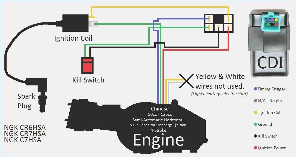
Each wire within a Gy6 Wiring Harness Diagram is assigned a specific color, consistently maintained throughout the diagram. This standardized color coding scheme enables technicians to quickly identify the purpose of each wire, reducing the likelihood of errors and misinterpretations. For instance, red wires are typically designated for positive connections, black wires for negative connections, and yellow wires for auxiliary or accessory functions.
The practical applications of color coding in Gy6 Wiring Harness Diagrams are far-reaching. During troubleshooting, color coding allows technicians to swiftly locate and isolate problematic circuits, minimizing downtime and maximizing efficiency. Additionally, color coding facilitates the identification of wire connections during maintenance or repair tasks, reducing the risk of incorrect connections and ensuring the proper functioning of the electrical system.
Testing
Testing plays a vital role in the context of Gy6 Wiring Harness Diagrams, serving as a cornerstone for ensuring the accuracy and reliability of these intricate schematics. Through a series of systematic tests, technicians can verify the integrity of electrical connections, identify potential faults, and assess the overall functionality of the wiring harness.
One critical aspect of testing involves the use of a multimeter, a versatile tool that measures electrical properties such as voltage, current, and resistance. By connecting the multimeter to specific points within the wiring harness, technicians can verify the continuity of circuits, detect open or short circuits, and measure voltage levels to ensure they are within acceptable ranges. This process allows for the identification of faulty wires, loose connections, or other issues that could compromise the proper functioning of the electrical system.
Real-life examples of testing in Gy6 Wiring Harness Diagrams abound. During the manufacturing process, rigorous testing is conducted to ensure that each wiring harness meets the required specifications and performs as intended. This involves simulating real-world conditions and subjecting the harness to various tests, including voltage withstand tests, insulation resistance tests, and continuity tests. By identifying and rectifying any potential issues at this stage, manufacturers can minimize the risk of failures in the field.
The practical applications of understanding the connection between testing and Gy6 Wiring Harness Diagrams are extensive. Accurate testing enables technicians to troubleshoot electrical problems efficiently, reducing downtime and ensuring optimal performance of the engine. Moreover, it contributes to the safety and reliability of the electrical system, preventing potential hazards and ensuring the longevity of the engine.
Troubleshooting
The relationship between “Troubleshooting” and “Gy6 Wiring Harness Diagram” is tightly intertwined, with troubleshooting serving as a critical component of understanding, maintaining, and repairing the intricate electrical system of a Gy6 engine. The Gy6 Wiring Harness Diagram provides a detailed visual representation of the electrical connections within the engine, enabling technicians and enthusiasts to identify and resolve electrical issues efficiently.
Troubleshooting plays a pivotal role in diagnosing and rectifying electrical problems within the Gy6 engine. When faced with an electrical issue, technicians refer to the Gy6 Wiring Harness Diagram to trace the electrical circuits, identify potential faults, and determine the root cause of the problem. The diagram serves as a roadmap, guiding technicians through the electrical system and allowing them to pinpoint the specific component or connection causing the issue.
Real-life examples of troubleshooting within Gy6 Wiring Harness Diagrams are abundant. Suppose an engine experiences a sudden loss of power. By referring to the wiring harness diagram, a technician can systematically check the electrical connections, starting from the battery and following the circuit through the ignition system, sensors, and other components. This process of elimination helps identify the faulty component or loose connection, enabling the technician to make the necessary repairs or replacements.
Understanding the connection between troubleshooting and Gy6 Wiring Harness Diagrams has practical applications in various settings. For instance, in automotive repair shops, technicians heavily rely on wiring harness diagrams to diagnose and resolve electrical issues in Gy6 engines, ensuring the efficient operation of vehicles. Additionally, hobbyists and enthusiasts working on their own engines find these diagrams invaluable for troubleshooting and maintaining their engines, promoting self-sufficiency and cost savings.
Repair
In the context of Gy6 Wiring Harness Diagrams, the aspect of “Repair” holds significant importance, as it encompasses the processes and techniques involved in restoring a faulty wiring harness to its proper working condition. Understanding the different facets of “Repair” is essential for maintaining the integrity and functionality of the electrical system in Gy6 engines.
- Component Replacement: When a specific component within the wiring harness, such as a fuse, relay, or connector, fails or becomes damaged, it needs to be replaced to restore the circuit’s functionality. This involves identifying the faulty component, disconnecting it from the harness, and installing a new one with the same specifications.
- Wire Repair: In cases where individual wires become damaged or frayed, repair techniques can be employed to restore their conductivity. This may involve soldering, crimping, or heat-shrinking the affected area to ensure a secure and reliable connection.
- Harness Repair: If the damage to the wiring harness is extensive, it may be necessary to repair or replace the entire harness. This process requires careful disassembly of the engine components, removal of the old harness, and installation of a new or repaired harness.
- Grounding Verification: Proper grounding is crucial for the electrical system to function correctly. Repairing or restoring grounding points ensures a complete circuit and prevents electrical issues.
Understanding the “Repair” aspect of Gy6 Wiring Harness Diagrams empowers individuals to troubleshoot and resolve electrical problems effectively. It enables technicians and enthusiasts to identify faulty components, repair damaged wires, and restore the functionality of the wiring harness, ensuring the optimal performance of Gy6 engines.
Replacement
Within the context of Gy6 Wiring Harness Diagrams, the aspect of “Replacement” holds significant importance, as it encompasses the processes and techniques involved in restoring a faulty wiring harness to its proper working condition. Understanding the different facets of “Replacement” is essential for maintaining the integrity and functionality of the electrical system in Gy6 engines.
- Component Replacement: When a specific component within the wiring harness, such as a fuse, relay, or connector, fails or becomes damaged, it needs to be replaced to restore the circuit’s functionality. This involves identifying the faulty component, disconnecting it from the harness, and installing a new one with the same specifications.
- Wire Repair: In cases where individual wires become damaged or frayed, repair techniques can be employed to restore their conductivity. This may involve soldering, crimping, or heat-shrinking the affected area to ensure a secure and reliable connection.
- Harness Replacement: If the damage to the wiring harness is extensive, it may be necessary to replace the entire harness. This process requires careful disassembly of the engine components, removal of the old harness, and installation of a new or repaired harness.
- Grounding Verification: Proper grounding is crucial for the electrical system to function correctly. Repairing or restoring grounding points ensures a complete circuit and prevents electrical issues.
Understanding the “Replacement” aspect of Gy6 Wiring Harness Diagrams empowers individuals to troubleshoot and resolve electrical problems effectively. It enables technicians and enthusiasts to identify faulty components, repair damaged wires, and restore the functionality of the wiring harness, ensuring the optimal performance of Gy6 engines.
Maintenance
Within the realm of “Gy6 Wiring Harness Diagrams,” the concept of “Maintenance” emerges as a critical component, inextricably linked to the proper functioning and longevity of the electrical system in Gy6 engines. Maintenance encompasses a range of activities and practices aimed at preserving the integrity and performance of the wiring harness, ensuring its continued reliability.
Regular and proactive maintenance is essential to prevent potential issues and ensure the accuracy and reliability of the Gy6 Wiring Harness Diagram. This involves periodic inspections and testing to identify any signs of damage, corrosion, or loose connections. By addressing these issues promptly, technicians can minimize the risk of electrical faults, optimize engine performance, and extend the lifespan of the wiring harness.
Real-life examples of maintenance within Gy6 Wiring Harness Diagrams abound. In automotive repair shops, technicians routinely perform maintenance checks on Gy6 wiring harnesses as part of regular servicing. These checks involve visual inspections, continuity testing, and verification of proper grounding connections. By identifying and resolving potential problems early on, technicians can prevent costly repairs and ensure the safety and reliability of the vehicle’s electrical system.
Understanding the connection between maintenance and Gy6 Wiring Harness Diagrams has practical applications in various settings. For instance, in the aviation industry, regular maintenance of wiring harnesses is crucial to ensure the safety and reliability of aircraft electrical systems. By adhering to strict maintenance schedules and following manufacturer guidelines, aviation technicians can minimize the risk of electrical failures and contribute to the safe operation of aircraft.
Safety
Within the context of “Gy6 Wiring Harness Diagram,” the aspect of “Safety” holds paramount importance, as it encompasses the essential measures and considerations for ensuring the protection of individuals and equipment while working with electrical systems. Understanding the safety implications and adhering to proper safety protocols is crucial to prevent electrical hazards, accidents, and potential harm.
- Electrical Hazards: Gy6 Wiring Harness Diagrams provide a comprehensive overview of the electrical connections within the engine, highlighting potential hazards such as exposed wires, faulty components, and incorrect connections. By studying the diagram and following safety guidelines, technicians can identify and mitigate these hazards, minimizing the risk of electrical shocks, fires, and other accidents.
- Color Coding: The color-coded wires depicted in Gy6 Wiring Harness Diagrams play a vital role in ensuring safety. Each color represents a specific function or voltage level, allowing technicians to easily identify and trace circuits. This color coding helps prevent misconnections and accidental contact with live wires, reducing the likelihood of electrical incidents.
- Grounding: Proper grounding is essential for the safe operation of any electrical system. Gy6 Wiring Harness Diagrams indicate the grounding points within the engine, ensuring that components are properly earthed to prevent voltage spikes, electrical noise, and potential damage to equipment.
- Maintenance and Inspection: Regular maintenance and inspection of the wiring harness are crucial for maintaining safety. By following the Gy6 Wiring Harness Diagram, technicians can identify loose connections, damaged wires, or any other irregularities that could pose a safety hazard. Prompt attention to maintenance needs helps prevent electrical faults and ensures the continued safe operation of the engine.
Understanding the safety implications and adhering to proper safety protocols when working with Gy6 Wiring Harness Diagrams is paramount for safeguarding individuals, equipment, and the overall integrity of the electrical system. By recognizing potential hazards, utilizing color coding, ensuring proper grounding, and conducting regular maintenance and inspections, technicians can mitigate risks, prevent accidents, and ensure the safe and reliable operation of Gy6 engines.
Performance
In the realm of Gy6 Wiring Harness Diagrams, “Performance” emerges as a critical component, directly influencing the efficiency, reliability, and overall functionality of the engine’s electrical system. The accuracy and completeness of the wiring harness diagram play a pivotal role in determining the performance of the engine, as it serves as a blueprint for the electrical connections and pathways.
A well-designed Gy6 Wiring Harness Diagram ensures optimal current flow, minimizes voltage drops, and prevents intermittent faults. This translates into improved engine performance, smoother operation, and increased fuel efficiency. Conversely, an inaccurate or incomplete diagram can lead to electrical problems, such as short circuits, open circuits, and ground faults, resulting in decreased performance, engine damage, or even safety hazards.
Real-life examples abound where “Performance” and “Gy6 Wiring Harness Diagram” are inextricably linked. In the automotive industry, manufacturers rely on precise wiring harness diagrams to optimize engine performance and meet stringent emissions standards. Similarly, in the aviation sector, aircraft rely on accurate wiring diagrams to ensure the safe and efficient operation of critical electrical systems.
Understanding the connection between “Performance” and “Gy6 Wiring Harness Diagram” has far-reaching practical applications. For technicians and engineers, it emphasizes the importance of using accurate and up-to-date diagrams during installation, maintenance, and troubleshooting. For enthusiasts and hobbyists, it underscores the need for thorough research and understanding of the wiring harness diagram to maximize engine performance and prevent potential issues.


Related Posts


