A GY6 stator wiring diagram illustrates the electrical connections between the components of a GY6 scooter engine stator. This 150cc, air-cooled, single-cylinder engine is commonly used in scooters and mopeds. The stator is responsible for generating alternating current (AC) electricity, which is then converted to direct current (DC) by the rectifier and used to power the vehicle’s electrical systems, including the ignition, lights, and horn.
Understanding the GY6 stator wiring diagram is crucial for maintaining and troubleshooting the electrical system of a scooter or moped. A faulty wiring diagram can lead to electrical problems, such as a weak or intermittent spark, poor battery charging, or even a complete electrical failure. It’s also essential for customizing or upgrading the electrical system, as it provides a visual guide to the connections and allows for modifications, such as adding additional accessories or upgrading the lighting system.
The development of the GY6 stator has played a significant role in the evolution of scooter and moped engines. The GY6 engine, with its reliable and efficient stator, has become a popular choice for manufacturers due to its low cost and ease of maintenance. This has led to the widespread adoption of the GY6 stator in scooters and mopeds around the world, making it one of the most common and widely used stator designs in the industry.
In the following sections, we will delve deeper into the GY6 stator wiring diagram, exploring its components, connections, and troubleshooting techniques. We will also discuss advanced topics such as stator testing, rewinding, and performance modifications.
Understanding the key aspects of a GY6 stator wiring diagram is essential for maintaining, troubleshooting, and modifying the electrical system of a scooter or moped.
- Components: Stator coil, flywheel, pick-up coil, ignition coil
- Connections: Wires, connectors, terminals
- Testing: Ohmmeter, multimeter
- Troubleshooting: Electrical problems, weak spark, poor charging
- Maintenance: Cleaning, inspection, replacement
- Upgrading: Higher output stator, custom lighting
- Performance: Engine performance, fuel efficiency
- Safety: Electrical hazards, proper installation
- Availability: OEM and aftermarket options
These aspects are interconnected and play vital roles in the proper functioning of the GY6 stator wiring diagram. For example, understanding the components and connections is crucial for troubleshooting electrical problems, while maintenance and testing ensure optimal performance and longevity. Upgrading and performance modifications can enhance the electrical system and overall riding experience. Safety considerations are paramount to prevent electrical hazards and ensure proper installation. The availability of OEM and aftermarket options provides flexibility and customization possibilities.
Components
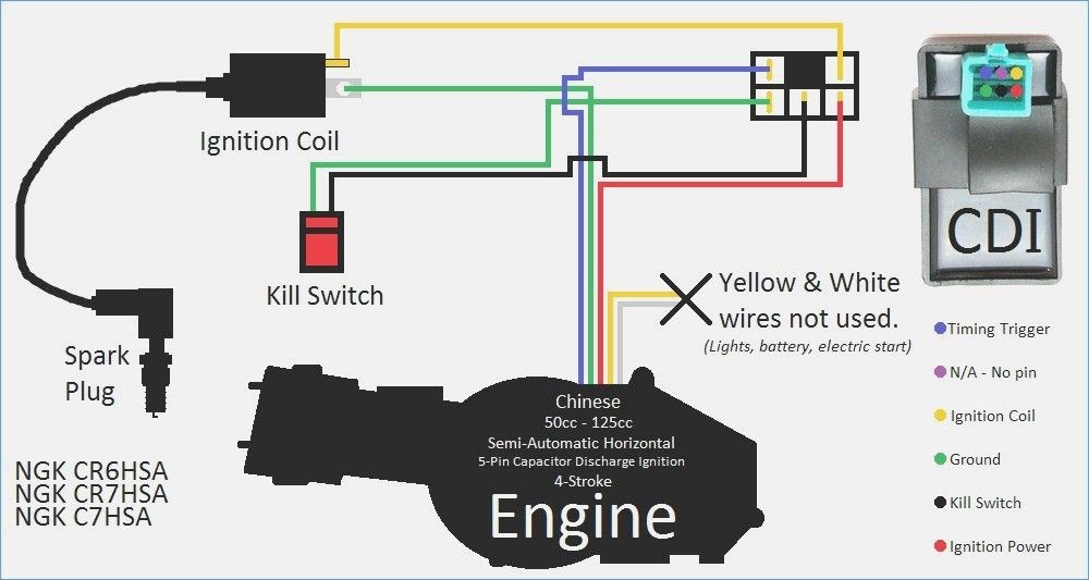
The stator coil, flywheel, pick-up coil, and ignition coil are critical components of a GY6 stator wiring diagram. The stator coil is a stationary set of coils that generates alternating current (AC) electricity when the flywheel rotates around it. The flywheel is a heavy metal disc that provides inertia to the engine and helps to smooth out the power delivery. The pick-up coil is a small coil of wire that is located near the flywheel and generates a pulse of electricity each time a metal tab on the flywheel passes by. This pulse of electricity is used to trigger the ignition coil, which generates a high-voltage spark to ignite the air-fuel mixture in the engine’s cylinder.
The GY6 stator wiring diagram shows how these components are connected together and how they work together to generate electricity and power the engine. If any of these components fail, the engine will not run properly. For example, if the stator coil fails, the engine will not generate any electricity and the spark plug will not fire. If the flywheel fails, the engine will not have enough inertia to run smoothly and will likely stall. If the pick-up coil fails, the ignition coil will not receive the signal to generate a spark and the engine will not start. If the ignition coil fails, the spark plug will not receive the high-voltage spark and the engine will not run.
Understanding the connection between these components and the GY6 stator wiring diagram is essential for troubleshooting and repairing a scooter or moped engine. By knowing how these components work together, you can quickly identify and fix any problems that may arise.
Connections
The wires, connectors, and terminals in a GY6 stator wiring diagram play a critical role in the proper functioning of the electrical system. These components provide the physical pathways for the flow of electricity between the stator coil, flywheel, pick-up coil, ignition coil, and other electrical components. Without secure and reliable connections, the electrical system would not be able to generate and distribute electricity, resulting in a non-functioning engine.
The wires in a GY6 stator wiring diagram are typically made of copper, which is an excellent conductor of electricity. The connectors are typically made of metal or plastic, and they provide a secure and reliable connection between the wires and the other electrical components. The terminals are typically made of metal, and they provide a point of connection for the wires to the electrical components. The terminals are often crimped or soldered to the wires to ensure a secure connection.
Understanding the connections between the wires, connectors, and terminals in a GY6 stator wiring diagram is essential for troubleshooting and repairing electrical problems. For example, if a wire becomes loose or disconnected, the electrical current will not be able to flow properly and the engine will not run properly. If a connector becomes damaged or corroded, the electrical current will not be able to flow properly and the engine will not run properly. If a terminal becomes loose or corroded, the electrical current will not be able to flow properly and the engine will not run properly.
By understanding the connections between the wires, connectors, and terminals in a GY6 stator wiring diagram, you can quickly identify and fix any problems that may arise. This will help to keep your scooter or moped running smoothly and safely.
Testing
When it comes to troubleshooting and repairing a GY6 scooter or moped’s electrical system, understanding the GY6 stator wiring diagram is not enough. Knowing how to test the stator coil, flywheel, pick-up coil, ignition coil, and other electrical components using an ohmmeter or multimeter is also crucial. These tools allow you to measure the resistance, voltage, and current in different parts of the electrical system, which can help you identify faulty components and diagnose problems.
-
Resistance Testing:
Resistance testing involves using an ohmmeter to measure the resistance of the stator coil, flywheel, pick-up coil, and ignition coil. The resistance of a component should be within a specific range specified by the manufacturer. If the resistance is too high or too low, it could indicate a problem with the component.
-
Voltage Testing:
Voltage testing involves using a voltmeter to measure the voltage output of the stator coil and ignition coil. The voltage output should be within a specific range specified by the manufacturer. If the voltage output is too low or too high, it could indicate a problem with the component.
-
Continuity Testing:
Continuity testing involves using an ohmmeter to check if there is a complete circuit between two points in the electrical system. This test can be used to identify broken wires, loose connections, and other problems that could prevent the electrical system from functioning properly.
-
Diode Testing:
Diode testing involves using an ohmmeter or multimeter to check the functionality of diodes in the electrical system. Diodes are one-way electrical valves that allow current to flow in only one direction. If a diode is faulty, it can prevent the electrical system from functioning properly.
By understanding how to use an ohmmeter or multimeter to test the electrical components in a GY6 stator wiring diagram, you can quickly and easily identify and diagnose problems with the electrical system. This will help you to keep your scooter or moped running smoothly and safely.
Troubleshooting
Troubleshooting electrical problems, weak spark, and poor charging is a critical aspect of understanding a GY6 stator wiring diagram. By comprehending the relationship between these issues and the wiring diagram, individuals can effectively diagnose and resolve electrical faults within their scooter or moped.
A GY6 stator wiring diagram provides a visual representation of the electrical connections between the stator coil, flywheel, pick-up coil, ignition coil, and other electrical components. This diagram serves as a roadmap for tracing electrical circuits and identifying potential problem areas. When troubleshooting electrical problems, such as a weak spark or poor charging, the wiring diagram becomes an essential tool for isolating the source of the issue.
For instance, if a scooter experiences a weak spark, the wiring diagram can guide the mechanic in checking the connections between the stator coil and the ignition coil. A loose or corroded connection can disrupt the flow of electricity, resulting in a weak spark. Similarly, if the scooter exhibits poor charging, the wiring diagram can help trace the circuit from the stator coil to the voltage regulator and battery. A faulty voltage regulator or a break in the wiring can hinder the proper charging of the battery.
Understanding the GY6 stator wiring diagram empowers individuals with the knowledge to diagnose and repair electrical problems, weak spark, and poor charging issues. By utilizing the wiring diagram as a troubleshooting tool, mechanics and enthusiasts can efficiently identify faulty components, repair connections, and restore the proper functioning of the electrical system. This understanding not only ensures the smooth operation of the scooter or moped but also promotes safety by preventing electrical hazards and maintaining optimal performance.
Maintenance
Maintaining the electrical system of a scooter or moped is important for ensuring its reliability and performance. Regular cleaning, inspection, and replacement of components are essential aspects of maintenance that directly impact the GY6 stator wiring diagram and the overall functionality of the electrical system.
Cleaning the electrical components removes dirt, debris, and corrosion that can interfere with electrical connections and cause problems. For example, a dirty stator coil can lead to poor charging or a weak spark. Inspecting the electrical components for damage or wear is also crucial. A damaged wire or a loose connection can disrupt the flow of electricity and cause electrical problems. Replacing faulty components is necessary to restore the proper functioning of the electrical system. A faulty ignition coil, for instance, can prevent the engine from starting or running smoothly.
By understanding the GY6 stator wiring diagram, individuals can identify the location of electrical components and perform maintenance tasks effectively. The wiring diagram provides a visual representation of the electrical system, making it easier to trace circuits and locate problem areas. Regular maintenance helps to prevent electrical problems, ensures optimal performance, and prolongs the lifespan of the scooter or moped’s electrical system.
Upgrading
Modifying a scooter or moped’s electrical system to incorporate a higher output stator and custom lighting requires a thorough understanding of the GY6 stator wiring diagram. This upgrade can enhance the electrical system’s capabilities and provide additional functionality, but it also necessitates careful consideration of the wiring diagram to ensure proper installation and operation.
-
Higher Output Stator:
Installing a higher output stator can provide more electrical power to the scooter or moped’s electrical system. This can be beneficial for powering additional accessories, such as high-power lighting or heated grips, or for improving the charging capacity of the battery. The wiring diagram is essential for determining the compatibility of the new stator with the existing electrical system and for ensuring that it is properly connected to the voltage regulator and battery.
-
Custom Lighting:
Custom lighting, such as LED headlights or taillights, can enhance the visibility and style of a scooter or moped. The wiring diagram is crucial for determining the appropriate wiring connections for the custom lighting and for ensuring that it is compatible with the electrical system. Modifying the wiring diagram may be necessary to accommodate the custom lighting, and the diagram will also help to identify any additional components, such as relays or resistors, that may be required.
-
Electrical Load:
Upgrading to a higher output stator and custom lighting will increase the electrical load on the system. The wiring diagram is essential for assessing the capacity of the existing wiring and components to handle the increased load. Upgrading the wiring or other components may be necessary to ensure that the electrical system can safely and reliably power the new components.
-
Compatibility:
When upgrading the stator or lighting, it is crucial to consider compatibility with the existing electrical system. The wiring diagram will provide information about the voltage and current requirements of the electrical system, which will help to determine the compatibility of the new components. Installing incompatible components can damage the electrical system or lead to other problems.
By understanding the GY6 stator wiring diagram and carefully considering the electrical load and compatibility, individuals can successfully upgrade their scooter or moped’s electrical system with a higher output stator and custom lighting. This can enhance the functionality, visibility, and style of the vehicle while ensuring the safety and reliability of the electrical system.
Performance
In the realm of GY6 scooter and moped engines, the stator wiring diagram plays a pivotal role in optimizing engine performance and fuel efficiency. By understanding the intricate connections between the stator coil, flywheel, pick-up coil, and ignition coil, enthusiasts and mechanics can fine-tune the electrical system to maximize power output and minimize fuel consumption. Here are some key aspects to consider:
-
Ignition timing:
The GY6 stator wiring diagram provides insights into the timing of the ignition spark. Adjusting the timing can optimize the combustion process, leading to improved engine performance and fuel efficiency.
-
Stator coil resistance:
The resistance of the stator coil directly affects the voltage and current output of the electrical system. By modifying the coil’s resistance, it is possible to fine-tune the power output and fuel consumption.
-
Flywheel weight:
The weight of the flywheel influences the engine’s inertia and smoothness of operation. A heavier flywheel can improve low-end torque and fuel efficiency, while a lighter flywheel can enhance high-RPM performance.
-
Pick-up coil gap:
The gap between the pick-up coil and the flywheel affects the timing and strength of the ignition spark. Adjusting the gap can optimize engine performance and reduce fuel consumption.
By carefully considering these aspects and making informed adjustments based on the GY6 stator wiring diagram, it is possible to enhance the overall performance and fuel efficiency of a scooter or moped engine. This can lead to a more responsive and enjoyable riding experience while also reducing operating costs.
Safety
The GY6 stator wiring diagram plays a critical role in ensuring the safe and proper installation of the electrical system in a scooter or moped. Electrical hazards can arise from faulty wiring, improper connections, or incorrect component selection, and the wiring diagram provides a visual representation of the electrical system that helps to prevent these hazards.
A properly installed electrical system is essential for the safe operation of a scooter or moped. Electrical hazards can cause fires, electric shock, or damage to the electrical components. The GY6 stator wiring diagram provides a step-by-step guide for installing the electrical system, ensuring that all connections are made correctly and that the system is properly grounded. This helps to prevent electrical hazards and ensures that the electrical system operates safely and efficiently.
For example, the wiring diagram specifies the correct gauge of wire to use for each connection, which is important for preventing overheating and electrical fires. It also shows the location of the grounding points, which are essential for protecting the electrical system from damage in the event of a short circuit. By following the wiring diagram carefully, users can ensure that the electrical system is installed safely and correctly.
Understanding the GY6 stator wiring diagram is also important for troubleshooting electrical problems. If a problem occurs, the wiring diagram can be used to trace the circuit and identify the faulty component. This can help to prevent further damage to the electrical system and ensure that the scooter or moped is repaired safely and correctly.
Availability
The availability of both OEM (Original Equipment Manufacturer) and aftermarket options for the GY6 stator wiring diagram is a critical factor for scooter and moped owners. OEM parts are designed and manufactured by the original equipment manufacturer, while aftermarket parts are manufactured by third-party companies. Both OEM and aftermarket parts can be used to replace or upgrade the stator wiring diagram on a scooter or moped.
OEM parts are typically more expensive than aftermarket parts, but they are also generally of higher quality. OEM parts are designed to meet the exact specifications of the original equipment manufacturer, and they are often made with higher-quality materials and workmanship. Aftermarket parts, on the other hand, are often made with less expensive materials and workmanship. This can lead to performance issues and a shorter lifespan for aftermarket parts.
However, aftermarket parts can offer some advantages over OEM parts. Aftermarket parts are often more affordable than OEM parts, and they can be more readily available. Aftermarket parts can also offer performance upgrades or other features that are not available from OEM parts. For example, some aftermarket stator wiring diagrams offer higher-output stators that can provide more power to the electrical system.
Ultimately, the decision of whether to use OEM or aftermarket parts for the GY6 stator wiring diagram depends on the individual owner’s needs and budget. If the owner is looking for the highest quality and performance, then OEM parts are the best option. If the owner is looking for a more affordable option, then aftermarket parts can be a good choice.


Related Posts


