Gy6 150cc Ignition Wiring Diagram is a technical representation that illustrates the electrical connections of the ignition system in a 150cc GY6 engine. It provides a comprehensive roadmap for the proper wiring of components, ensuring optimal engine performance.
The ignition wiring diagram is of paramount importance as it governs the proper functioning of the ignition system, responsible for initiating combustion within the engine cylinders. It ensures proper timing and synchronization of ignition events, leading to efficient engine operation, improved fuel economy, and reduced emissions.
Over the years, ignition wiring diagrams have evolved with technological advancements. Today, they incorporate sophisticated computer-aided design tools, resulting in more precise and reliable diagrams. This has contributed significantly to the improved performance and reliability of modern engines.
The Gy6 150cc Ignition Wiring Diagram plays a pivotal role in ensuring efficient engine operation, serving as a blueprint for the proper wiring of ignition system components. Understanding its key aspects is crucial for comprehending its function and significance:
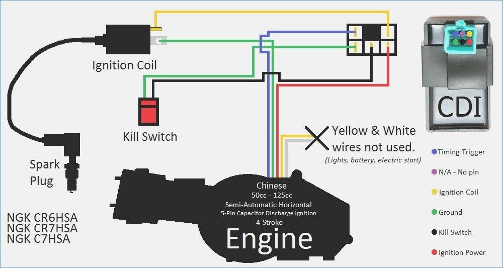
- Components: The diagram identifies the various components of the ignition system, including the ignition coil, spark plugs, ignition switch, and wiring harness.
- Connections: It outlines the electrical connections between these components, specifying the correct wire colors and connectors.
- Timing: The diagram ensures proper timing of ignition events, coordinating the spark delivery with the engine’s combustion cycle.
- Synchronization: It facilitates the synchronization of multiple ignition coils in multi-cylinder engines, ensuring optimal engine performance.
- Troubleshooting: The diagram aids in troubleshooting ignition system malfunctions, helping identify faulty components and connections.
- Performance optimization: By ensuring proper wiring and timing, the diagram contributes to improved engine performance, fuel efficiency, and reduced emissions.
- Safety: Correct ignition wiring is essential for preventing electrical hazards and ensuring safe engine operation.
- Compatibility: The diagram is specific to the Gy6 150cc engine, ensuring compatibility with its unique electrical system.
These key aspects collectively contribute to the effective functioning of the Gy6 150cc ignition system, underscoring the importance of adhering to the wiring diagram during installation and maintenance.
Components
The identification of components in the “Gy6 150cc Ignition Wiring Diagram” is a critical aspect that establishes the foundation for understanding the ignition system’s functionality. Each component plays a specific role in the ignition process, and their proper connection is essential for the engine to operate efficiently.
The ignition coil generates the high voltage required to create a spark at the spark plugs. The spark plugs ignite the air-fuel mixture within the engine’s cylinders, initiating combustion. The ignition switch controls the flow of electricity to the ignition coil, allowing the spark plugs to generate sparks only when the engine is running. The wiring harness connects all these components, providing a pathway for electrical signals and power.
By identifying and understanding the function of each component, technicians can effectively troubleshoot and repair ignition system issues. For instance, if the engine is not starting, a faulty ignition coil or spark plugs could be the cause. By referring to the wiring diagram, technicians can trace the electrical connections and identify the specific component that requires attention.
In summary, the identification of components within the “Gy6 150cc Ignition Wiring Diagram” is crucial for understanding the ignition system’s functionality, troubleshooting issues, and ensuring optimal engine performance.
Connections
The electrical connections outlined in the “Gy6 150cc Ignition Wiring Diagram” serve as the backbone of the ignition system, ensuring the proper flow of electricity between its various components. These connections establish a critical cause-and-effect relationship within the system, directly influencing its functionality and performance.
Each component in the ignition system relies on precise electrical connections to fulfill its specific role. For instance, the ignition coil requires a continuous supply of electricity from the battery to generate the high voltage necessary for spark generation. Similarly, the spark plugs depend on properly connected wires to receive this high voltage and create the sparks that ignite the air-fuel mixture within the engine’s cylinders. Without these connections, the ignition system would fail to function, resulting in engine starting problems or misfires.
The “Gy6 150cc Ignition Wiring Diagram” provides a detailed roadmap for establishing these electrical connections, specifying the correct wire colors and connectors for each component. By adhering to this diagram during installation and maintenance, technicians can ensure that the ignition system operates optimally. Incorrect connections can lead to a range of issues, including electrical shorts, component damage, and poor engine performance.
In summary, the electrical connections outlined in the “Gy6 150cc Ignition Wiring Diagram” are critical for the proper functioning of the ignition system. Understanding and following these connections are essential for technicians to troubleshoot and repair ignition system issues effectively, ensuring optimal engine performance and reliability.
Timing
Within the intricate network of components that comprise the “Gy6 150cc Ignition Wiring Diagram,” timing plays a crucial role in orchestrating the precise sequence of events that lead to efficient engine operation. The diagram meticulously outlines the timing parameters, ensuring that the ignition system delivers sparks at the optimal moment during the engine’s combustion cycle.
- Ignition Timing: The diagram specifies the precise moment when the spark plugs should generate sparks. This timing is critical as it directly influences the efficiency of fuel combustion and engine power output. Optimal ignition timing ensures that the air-fuel mixture ignites at the most advantageous point in the compression stroke, maximizing energy conversion and minimizing emissions.
- Synchronization: In multi-cylinder engines, the ignition system must coordinate the spark delivery to multiple cylinders in a synchronized manner. The wiring diagram outlines the connections and timing sequence to ensure that each cylinder receives a spark at the appropriate time, maintaining smooth engine operation and preventing misfires.
- Sensor Inputs: The diagram incorporates inputs from various sensors, such as the crankshaft position sensor and camshaft position sensor, to determine the engine’s operating conditions. These inputs dynamically adjust the ignition timing based on factors like engine speed and load, optimizing performance across different operating scenarios.
- Advance and Retard: The diagram may include provisions for adjusting ignition timing under specific circumstances. For instance, during acceleration, the ignition timing may be advanced to improve power delivery, while during deceleration, it may be retarded to reduce emissions.
In summary, the “Gy6 150cc Ignition Wiring Diagram” ensures proper timing of ignition events by specifying the optimal spark timing, synchronizing spark delivery in multi-cylinder engines, incorporating sensor inputs for dynamic adjustments, and providing options for ignition timing advance and retard. By adhering to these timing parameters, the ignition system contributes significantly to engine efficiency, power output, and overall performance.
Synchronization
Within the comprehensive framework of the “Gy6 150cc Ignition Wiring Diagram,” synchronization plays a pivotal role in coordinating the intricate dance of multiple ignition coils in multi-cylinder engines. This aspect of the diagram ensures that each cylinder receives a spark at the precise moment, enabling smooth and efficient engine operation.
- Timing Precision: In multi-cylinder engines, the ignition timing for each cylinder must be precisely aligned to match the piston’s position and the combustion cycle. The wiring diagram meticulously outlines the connections and timing sequence to achieve this synchronization, preventing misfires and ensuring optimal combustion efficiency.
- Coil Coordination: The diagram specifies the connections between the ignition coils and the spark plugs in each cylinder, ensuring that the coils deliver high voltage sparks in a synchronized manner. This coordination is crucial for maintaining consistent ignition timing across all cylinders, resulting in balanced engine performance.
- Sensor Inputs: The wiring diagram incorporates inputs from sensors, such as the crankshaft position sensor, to determine the engine’s operating conditions and adjust the ignition timing accordingly. This dynamic synchronization optimizes engine performance under varying loads and speeds, enhancing fuel efficiency and reducing emissions.
- Sequential Firing Order: For multi-cylinder engines with an odd number of cylinders, the wiring diagram establishes a specific firing order to maintain smooth engine operation. The diagram outlines the sequence in which the ignition coils fire, ensuring that the combustion pulses are evenly distributed, minimizing vibrations and maximizing power output.
In conclusion, the synchronization aspect of the “Gy6 150cc Ignition Wiring Diagram” is a critical factor in achieving optimal engine performance in multi-cylinder configurations. By precisely coordinating the timing and firing sequence of multiple ignition coils, the diagram ensures efficient combustion, smooth engine operation, and enhanced power delivery.
Troubleshooting
The “Gy6 150cc Ignition Wiring Diagram” serves as a valuable diagnostic tool for troubleshooting ignition system malfunctions, enabling technicians to pinpoint faulty components and connections with greater efficiency. The diagram provides a comprehensive overview of the ignition system’s electrical architecture, allowing technicians to trace the flow of electricity and identify potential points of failure.
When faced with an ignition system issue, technicians can refer to the wiring diagram to systematically check each component and connection. They can use a multimeter to measure voltage and resistance values, comparing them to the specifications provided in the diagram. This helps isolate the faulty component or connection, allowing for targeted repairs.
For example, if an engine is experiencing misfires, the diagram can guide the technician in checking the spark plug wires for cracks or loose connections. The technician can then use a spark tester to verify if the spark plugs are generating sparks. If no spark is present, the diagram can help identify the source of the problem, such as a faulty ignition coil or a break in the wiring harness.
The ability to troubleshoot ignition system malfunctions using the “Gy6 150cc Ignition Wiring Diagram” is a crucial skill for technicians. It enables them to diagnose and repair ignition system issues quickly and accurately, minimizing vehicle downtime and ensuring optimal engine performance.
Performance optimization
Within the context of the “Gy6 150cc Ignition Wiring Diagram,” performance optimization emerges as a crucial aspect that directly influences the engine’s overall functionality and efficiency. By meticulously outlining the proper wiring and timing configurations, the diagram plays a pivotal role in achieving optimal engine performance, maximizing fuel economy, and minimizing harmful emissions.
- Precise Ignition Timing: The diagram ensures accurate ignition timing, optimizing the moment of spark delivery in relation to the piston’s position within the cylinder. This precise timing enhances combustion efficiency, leading to increased power output and improved fuel utilization.
- Optimized Spark Energy: By ensuring proper wiring connections, the diagram facilitates the delivery of sufficient electrical energy to the spark plugs. This optimized spark energy results in more robust and consistent ignition, contributing to cleaner combustion and reduced emissions.
- Reduced Electrical Resistance: The diagram specifies the correct wire gauges and connectors, minimizing electrical resistance within the ignition system. This reduced resistance allows for efficient current flow, ensuring reliable spark generation and preventing energy loss.
- Minimized Timing Fluctuations: The diagram incorporates provisions for stabilizing ignition timing under varying operating conditions. This minimizes timing fluctuations, maintaining optimal combustion efficiency across different engine loads and speeds, resulting in improved fuel economy and reduced emissions.
In conclusion, the performance optimization aspect of the “Gy6 150cc Ignition Wiring Diagram” underscores the critical role of proper wiring and timing in achieving optimal engine performance. By adhering to the diagram’s specifications, technicians can ensure precise ignition timing, optimized spark energy, reduced electrical resistance, and minimized timing fluctuations. These factors collectively contribute to enhanced engine power, improved fuel efficiency, and reduced emissions, maximizing the overall performance and efficiency of the Gy6 150cc engine.
Safety
In the context of the “Gy6 150cc Ignition Wiring Diagram,” safety emerges as a paramount consideration that underscores the critical importance of adhering to proper wiring practices. Incorrect ignition wiring can lead to a range of electrical hazards, posing significant risks to both the engine and the vehicle’s occupants.
- Electrical Shorts: Improper wiring can create electrical shorts, causing a sudden and uncontrolled flow of current. This can result in damage to electrical components, overheating, and even fires.
- Voltage Spikes: Incorrect wiring can lead to voltage spikes, which are sudden increases in electrical voltage. These spikes can damage sensitive electronic components, such as the engine control unit (ECU), potentially causing engine malfunctions or even catastrophic failures.
- Ground Faults: Wiring faults can create ground faults, where electrical current takes an unintended path to the ground. This can lead to electrical shocks, component damage, and reduced ignition system performance.
- Arcing: Loose or damaged connections can create arcing, which is the formation of an electrical spark or arc. Arcing can ignite flammable materials, causing fires or explosions.
By providing a comprehensive roadmap for proper ignition wiring, the “Gy6 150cc Ignition Wiring Diagram” serves as a vital safety document. It ensures that technicians and enthusiasts alike have the necessary information to wire the ignition system correctly, minimizing the risks of electrical hazards and ensuring safe and reliable engine operation.
Compatibility
The “Gy6 150cc Ignition Wiring Diagram” is specifically tailored to the unique electrical system of the Gy6 150cc engine, ensuring compatibility and optimal functionality. This specificity stems from the fact that different engines have distinct electrical configurations, including variations in component specifications, wiring arrangements, and sensor inputs. A wiring diagram designed for one engine may not be compatible with another due to these differences.
For instance, the Gy6 150cc engine employs a specific type of ignition coil with a unique resistance value and inductance. The wiring diagram provides the exact specifications for this ignition coil, ensuring that the correct component is used. Additionally, the diagram outlines the specific wiring connections between the ignition coil, spark plugs, and other electrical components, ensuring that the electrical signals are transmitted correctly.
Understanding the compatibility aspect of the “Gy6 150cc Ignition Wiring Diagram” is crucial for technicians and enthusiasts alike. Using the correct wiring diagram for the specific engine model ensures that the ignition system operates as intended, preventing potential issues such as misfires, poor engine performance, or even electrical damage. Adhering to the diagram’s specifications guarantees compatibility with the unique electrical system of the Gy6 150cc engine, resulting in reliable and efficient engine operation.


Related Posts


