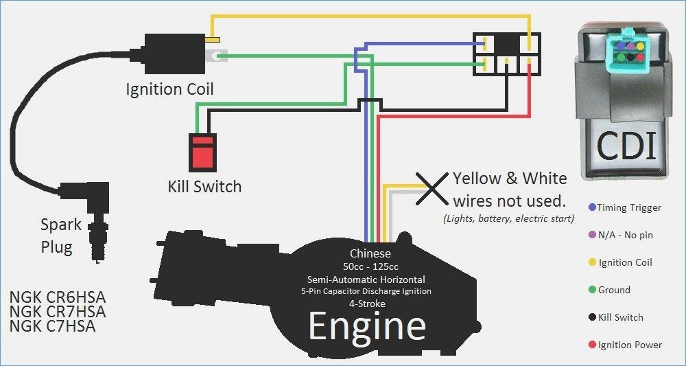
A Gy6 150cc CDI Wiring Diagram is a schematic representation of the electrical connections within a GY6 150cc scooter’s Capacitor Discharge Ignition (CDI) system. This diagram provides a visual guide to the wiring harness, showing the connections between the CDI unit, ignition coil, spark plug, battery, and other electrical components. For example, a typical GY6 150cc CDI Wiring Diagram would illustrate the red wire from the battery connecting to the positive terminal of the CDI unit, the black wire from the battery connecting to the negative terminal of the CDI unit, and the blue wire from the CDI unit connecting to the ignition coil.
Gy6 150cc CDI Wiring Diagrams are essential for troubleshooting ignition problems and performing electrical repairs. By following the diagram, technicians can trace the flow of electricity through the CDI system and identify any faulty connections or components. Additionally, CDI Wiring Diagrams can help prevent electrical fires by ensuring that all connections are made correctly.
A key historical development in CDI technology was the introduction of digital CDI units in the late 1980s. Digital CDI units are more accurate and reliable than analog CDI units, and they have become the standard in modern scooters. This transition to digital technology has greatly improved the performance and reliability of GY6 150cc scooters.
This article will delve deeper into the details of Gy6 150cc CDI Wiring Diagrams, including the various components, connections, and troubleshooting techniques. By understanding the principles behind these diagrams, readers will be better equipped to maintain and repair their own GY6 150cc scooters.
A Gy6 150cc CDI Wiring Diagram is a crucial component for understanding and maintaining the electrical system of a GY6 150cc scooter. It provides a visual representation of the connections between the CDI unit, ignition coil, spark plug, battery, and other electrical components. By understanding the key aspects of Gy6 150cc CDI Wiring Diagrams, technicians and scooter owners can troubleshoot ignition problems, perform electrical repairs, and ensure the proper functioning of their vehicles.
- Components: CDI unit, ignition coil, spark plug, battery, wires, connectors
- Connections: Electrical pathways between components
- Troubleshooting: Identifying and resolving ignition problems
- Repair: Replacing or fixing faulty components and connections
- Maintenance: Inspecting and cleaning electrical components
- Performance: Optimizing ignition timing for better engine performance
- Safety: Preventing electrical fires and ensuring safe operation
- Compatibility: Matching CDI Wiring Diagrams to specific GY6 150cc scooter models
- Customization: Modifying CDI Wiring Diagrams for performance enhancements
- Documentation: Referencing CDI Wiring Diagrams for future maintenance and repairs
These aspects are interconnected and essential for the proper functioning of a GY6 150cc scooter’s electrical system. By understanding the components, connections, and troubleshooting techniques, technicians can quickly identify and resolve ignition problems. Regular maintenance and inspection of electrical components, based on the CDI Wiring Diagram, can prevent costly repairs and ensure the safety and reliability of the scooter. Additionally, CDI Wiring Diagrams can be used for performance enhancements and customization, allowing scooter owners to optimize the ignition timing for improved engine performance.
Components
Within the intricate network of a GY6 150cc CDI Wiring Diagram, a multitude of components play vital roles in orchestrating the ignition process and ensuring the smooth operation of the scooter. These components, including the CDI unit, ignition coil, spark plug, battery, wires, and connectors, form a cohesive system that translates electrical energy into the spark that ignites the air-fuel mixture within the engine.
- CDI Unit: The heart of the ignition system, the CDI unit receives signals from the crankshaft position sensor and calculates the optimal timing for spark delivery. It then triggers the ignition coil to generate the high-voltage spark.
- Ignition Coil: Acting as a transformer, the ignition coil amplifies the voltage from the CDI unit and creates the high-voltage spark necessary to ignite the air-fuel mixture.
- Spark Plug: The final link in the ignition chain, the spark plug conducts the high-voltage spark from the ignition coil to the combustion chamber, creating the spark that ignites the air-fuel mixture.
- Battery: The battery provides the electrical power to the CDI unit and other electrical components of the scooter, ensuring a consistent and reliable source of energy for the ignition system.
- Wires: The electrical connections between the various components are established through a network of wires, which must be properly insulated and connected to ensure efficient current flow.
- Connectors: Connectors provide secure and reliable electrical connections between wires and components, allowing for easy disassembly and maintenance of the wiring harness.
These components, meticulously interconnected through the CDI Wiring Diagram, work in harmony to deliver the precise and timely spark required for optimal engine performance. By understanding the roles and relationships of these components, technicians and scooter owners can effectively troubleshoot ignition problems, perform maintenance, and ensure the longevity and reliability of their GY6 150cc scooters.
Connections
Within the intricate network of a GY6 150cc CDI Wiring Diagram, the electrical connections between components serve as the vital arteries that allow electrons to flow, orchestrating the complex interplay of electrical signals and power distribution necessary for the proper functioning of the scooter. These connections, meticulously planned and executed, form the backbone of the CDI system, ensuring that each component receives the electrical energy it needs to perform its designated task.
The CDI Wiring Diagram serves as the blueprint for these electrical pathways, detailing the precise connections between the CDI unit, ignition coil, spark plug, battery, and other electrical components. Without these connections, the CDI system would be nothing more than a collection of isolated components, unable to communicate or function as a cohesive unit. It is through these connections that electrical signals from the CDI unit can reach the ignition coil, triggering the generation of the high-voltage spark that ignites the air-fuel mixture within the engine. Similarly, the battery’s electrical power can flow through the wires and connectors to the CDI unit, providing the energy it needs to operate.
Real-life examples of these connections abound within the GY6 150cc CDI Wiring Diagram. The red wire, for instance, carries the positive voltage from the battery to the CDI unit, providing the power necessary for its operation. The black wire, on the other hand, serves as the ground connection, completing the electrical circuit and allowing current to flow. The blue wire, originating from the CDI unit, carries the high-voltage spark to the ignition coil, where it is amplified and sent to the spark plug for ignition.
Understanding the connections between components within the GY6 150cc CDI Wiring Diagram is of paramount importance for troubleshooting ignition problems and performing electrical repairs. By tracing the flow of electricity through the diagram, technicians can quickly identify any broken or loose connections, faulty components, or shorts that may be preventing the CDI system from functioning properly. This understanding also enables technicians to make modifications to the wiring harness, such as installing additional accessories or optimizing the ignition timing for improved engine performance.
In summary, the connections between components play a critical role in the GY6 150cc CDI Wiring Diagram, providing the electrical pathways necessary for the proper functioning of the ignition system. By understanding the importance of these connections and their relationship to the overall CDI system, technicians and scooter owners can effectively diagnose and resolve electrical problems, ensuring the reliable and efficient operation of their GY6 150cc scooters.
Troubleshooting
In the intricate realm of GY6 150cc scooters, the CDI Wiring Diagram serves as a guiding light for technicians and scooter owners alike, providing a roadmap to understanding and resolving ignition problems. Troubleshooting these issues requires a systematic approach, encompassing various facets that delve into the heart of the electrical system.
- Component Inspection: A thorough examination of the CDI unit, ignition coil, spark plug, and electrical connections can reveal loose wires, damaged components, or signs of corrosion. Visual inspection is a crucial step in identifying potential ignition problems.
- Electrical Testing: Utilizing a multimeter or other diagnostic tools, technicians can measure voltage and resistance at various points within the CDI Wiring Diagram. This helps identify electrical faults, open circuits, or short circuits, pinpointing the source of the ignition problem.
- Signal Analysis: Advanced troubleshooting techniques involve analyzing electrical signals using an oscilloscope. By observing the waveforms and comparing them to known good signals, technicians can detect timing issues, faulty sensors, or problems within the CDI unit itself.
- Diagnostic Codes: Modern GY6 150cc scooters may incorporate diagnostic systems that store error codes related to ignition problems. Retrieving and interpreting these codes can provide valuable insights, guiding technicians towards the root cause of the issue.
Troubleshooting ignition problems using the GY6 150cc CDI Wiring Diagram is a multi-faceted process that requires a combination of knowledge, experience, and diagnostic tools. By methodically examining components, testing electrical circuits, analyzing signals, and utilizing diagnostic codes, technicians can effectively identify and resolve ignition problems, ensuring the smooth and reliable operation of GY6 150cc scooters.
Repair
The GY6 150cc CDI Wiring Diagram serves as a valuable tool when performing repairs on faulty components and connections within the ignition system. By understanding the layout and functionality of the electrical components as depicted in the diagram, technicians can efficiently identify and resolve ignition problems. The diagram provides a visual representation of the electrical connections between the CDI unit, ignition coil, spark plug, battery, and other electrical components, allowing technicians to trace the flow of electricity and pinpoint the source of any malfunctions.
Real-life examples of repairs guided by the GY6 150cc CDI Wiring Diagram include replacing a faulty CDI unit, repairing a damaged ignition coil, or resolving loose connections within the wiring harness. The diagram helps technicians identify the specific component or connection that is causing the ignition problem, enabling them to make targeted repairs and restore the proper functioning of the ignition system. By following the diagram, technicians can ensure that all electrical connections are secure and that the components are receiving the correct voltage and signals.
The practical applications of understanding the GY6 150cc CDI Wiring Diagram extend beyond troubleshooting and repairs. Technicians can use the diagram to optimize the ignition timing for improved engine performance, modify the wiring harness for custom installations, and diagnose more complex electrical problems. The diagram serves as a reference point for maintenance and upgrades, allowing technicians to make informed decisions and ensure the longevity and reliability of the scooter’s electrical system.
In summary, the GY6 150cc CDI Wiring Diagram is an essential tool for repairing faulty components and connections within the ignition system. It provides a visual representation of the electrical connections, enabling technicians to quickly identify and resolve ignition problems. The diagram also serves as a valuable resource for maintenance, upgrades, and performance optimization, ensuring the smooth and reliable operation of GY6 150cc scooters.
Maintenance
Within the intricate network of the GY6 150cc CDI Wiring Diagram, regular maintenance is crucial to ensure the longevity and reliability of the scooter’s ignition system. Inspecting and cleaning electrical components proactively identifies potential issues and prevents minor problems from escalating into costly repairs.
- Spark Plug Inspection: Regularly removing and inspecting the spark plug can reveal signs of wear, fouling, or damage. Cleaning the spark plug electrodes and gap ensures optimal spark delivery and engine performance.
- Ignition Coil Inspection: Checking the ignition coil for cracks, corrosion, or loose connections is essential. A faulty ignition coil can disrupt the flow of high-voltage spark, leading to ignition problems.
- Electrical Connections: Inspecting all electrical connections within the CDI Wiring Diagram for signs of corrosion, loose wires, or damaged insulation is crucial. Secure connections ensure proper current flow and prevent electrical faults.
- Ground Connections: Particular attention should be paid to ground connections, as poor grounding can lead to electrical problems and affect the performance of the ignition system.
Regular maintenance and cleaning of electrical components, guided by the GY6 150cc CDI Wiring Diagram, help maintain optimal ignition timing, prevent electrical fires, and extend the lifespan of the scooter’s electrical system. By incorporating these practices into their maintenance routine, scooter owners can ensure the smooth and reliable operation of their vehicles.
Performance
In the realm of GY6 150cc scooters, optimizing ignition timing plays a crucial role in enhancing engine performance and overall riding experience. The GY6 150cc CDI Wiring Diagram provides a comprehensive blueprint for understanding and adjusting ignition timing, allowing technicians and scooter enthusiasts to fine-tune the ignition system for maximum efficiency and power.
Ignition timing refers to the precise moment when the spark plug delivers the spark to ignite the air-fuel mixture within the engine’s combustion chamber. By adjusting the ignition timing, technicians can optimize the timing of the spark relative to the piston’s position, ensuring that the air-fuel mixture is ignited at the ideal moment for maximum combustion efficiency. Advancing the ignition timing can result in increased power output, while retarding the ignition timing can improve fuel economy and reduce emissions.
The GY6 150cc CDI Wiring Diagram empowers technicians with the knowledge to identify and adjust the ignition timing parameters within the CDI unit. By manipulating the settings within the diagram, technicians can fine-tune the timing to suit specific engine modifications or performance requirements. Real-life examples of performance optimization through ignition timing adjustments include improving acceleration, enhancing top speed, and increasing fuel efficiency.
Understanding the relationship between ignition timing and engine performance, as outlined in the GY6 150cc CDI Wiring Diagram, enables technicians and scooter owners to make informed decisions regarding ignition system modifications. This understanding empowers them to optimize the ignition timing for their specific riding style, engine configuration, and performance goals. By carefully adjusting the ignition timing within the parameters of the CDI Wiring Diagram, scooter enthusiasts can unlock the full potential of their GY6 150cc engines, achieving optimal performance and riding satisfaction.
Safety
Within the intricate network of electrical components and connections depicted in the GY6 150cc CDI Wiring Diagram, safety plays a paramount role in preventing electrical fires and ensuring the safe operation of the scooter. Electrical fires, if left unchecked, can cause extensive damage to the scooter and pose a significant risk to the rider and surroundings. The CDI Wiring Diagram serves as a vital tool in understanding and implementing safety measures to mitigate these risks.
One of the primary causes of electrical fires in GY6 150cc scooters is faulty electrical connections. Loose or damaged wires, improper insulation, and poor grounding can create electrical arcs and generate excessive heat, potentially leading to a fire. The GY6 150cc CDI Wiring Diagram provides a clear visual representation of the electrical connections within the ignition system, allowing technicians to identify and address any potential issues proactively. By following the diagram and ensuring that all connections are secure, properly insulated, and grounded, the risk of electrical fires can be significantly reduced.
Another important aspect of electrical safety is the prevention of electrical overloads. Overloads occur when an electrical circuit is forced to carry more current than it is designed to handle, causing excessive heat buildup and potential damage to components. The CDI Wiring Diagram helps technicians identify the current-carrying capacity of each wire and component, enabling them to select appropriate components and ensure that the electrical system is not overloaded. By understanding the electrical load limits and adhering to the specifications outlined in the diagram, technicians can prevent electrical overloads and the associated fire risks.
In summary, the GY6 150cc CDI Wiring Diagram is a crucial tool for promoting electrical safety and preventing electrical fires in GY6 150cc scooters. It provides a comprehensive overview of the electrical connections and components, empowering technicians to identify and address potential hazards proactively. By following the diagram and implementing proper maintenance and inspection procedures, scooter owners can ensure the safe and reliable operation of their vehicles.
Compatibility
Within the realm of GY6 150cc CDI Wiring Diagrams, compatibility plays a pivotal role in ensuring the proper functioning and safe operation of the scooter’s ignition system. Matching the CDI Wiring Diagram to the specific model of GY6 150cc scooter is crucial to avoid electrical malfunctions, performance issues, and potential safety hazards.
- Specific Engine Configurations: GY6 150cc scooters come with varying engine configurations, such as air-cooled or liquid-cooled, and different valve arrangements, like 2-valve or 4-valve engines. Each engine configuration requires a specific CDI Wiring Diagram that aligns with its unique electrical requirements and ignition timing parameters.
- Electrical Component Compatibility: CDI Wiring Diagrams are tailored to match the specific electrical components installed in each GY6 150cc scooter model. These components include the CDI unit, ignition coil, spark plug, and other electrical components. Using a CDI Wiring Diagram designed for a different scooter model can result in mismatched connections and potential electrical issues.
- Compliance with Regulations: Different regions and countries have specific regulations regarding the electrical systems of vehicles, including GY6 150cc scooters. CDI Wiring Diagrams must comply with these regulations to ensure that the scooter meets the required safety and emission standards.
- Optimization for Performance: CDI Wiring Diagrams are optimized for the specific performance characteristics of each GY6 150cc scooter model. Factors such as ignition timing and spark duration are carefully calibrated to maximize engine performance, fuel efficiency, and emissions control.
Matching CDI Wiring Diagrams to specific GY6 150cc scooter models is essential for ensuring compatibility, preventing electrical problems, and optimizing performance. Using the correct CDI Wiring Diagram for a particular scooter model is crucial for its safe and reliable operation, allowing riders to enjoy a smooth and trouble-free riding experience.
Customization
In the realm of GY6 150cc scooters, enthusiasts often seek to enhance their vehicles’ performance by modifying the CDI Wiring Diagram. This practice involves altering the electrical connections and settings within the CDI unit to optimize ignition timing, spark duration, and other parameters that influence engine behavior. By understanding the relationship between customization and the GY6 150cc CDI Wiring Diagram, scooter owners can unlock the potential for improved acceleration, increased top speed, and enhanced overall performance.
The CDI Wiring Diagram serves as the blueprint for the scooter’s ignition system, providing a visual representation of the electrical connections between the CDI unit, ignition coil, spark plug, and other components. By modifying the diagram, enthusiasts can adjust the timing of the spark relative to the piston’s position, altering the combustion characteristics of the engine. For example, advancing the ignition timing can result in increased power output, while retarding the timing can improve fuel economy and reduce emissions.
Real-life examples of CDI Wiring Diagram modifications for performance enhancements include installing high-performance CDI units, modifying ignition coils for increased spark energy, and adjusting the spark plug gap for optimal combustion. These modifications require careful consideration of the scooter’s specific engine configuration and performance goals. By understanding the principles behind the CDI Wiring Diagram, enthusiasts can make informed decisions regarding customization, ensuring that their modifications are compatible with their scooter’s electrical system and do not compromise safety or reliability.
The practical applications of understanding the connection between customization and the GY6 150cc CDI Wiring Diagram extend beyond performance enhancements. It empowers enthusiasts to troubleshoot ignition problems, diagnose engine malfunctions, and optimize the scooter’s electrical system for specific riding styles and environmental conditions. By mastering the CDI Wiring Diagram, scooter owners gain a deeper understanding of their vehicles and the ability to customize them for a truly personalized riding experience.
Documentation
Within the realm of GY6 150cc CDI Wiring Diagrams, documentation plays a vital role in ensuring the longevity and reliability of the scooter’s electrical system. Referencing CDI Wiring Diagrams for future maintenance and repairs is a critical aspect of proper scooter care, providing a valuable resource for troubleshooting, diagnosing problems, and performing repairs.
The CDI Wiring Diagram serves as a comprehensive blueprint for the scooter’s ignition system, detailing the electrical connections between the CDI unit, ignition coil, spark plug, and other components. By referencing the diagram during maintenance and repairs, technicians and scooter owners can ensure that all electrical connections are secure, properly insulated, and compliant with the manufacturer’s specifications. This helps prevent electrical faults, short circuits, and other issues that could compromise the scooter’s performance or safety.
Real-life examples of referencing CDI Wiring Diagrams for future maintenance and repairs include troubleshooting ignition problems, diagnosing electrical faults, and performing component replacements. For instance, if a scooter experiences intermittent starting issues, referencing the CDI Wiring Diagram can help identify loose connections or faulty components within the ignition system. By following the diagram, technicians can systematically check each connection and component, ensuring that the ignition system is functioning corretamente. Similarly, when replacing a faulty CDI unit or ignition coil, referencing the CDI Wiring Diagram ensures that the new component is correctly installed and connected, preventing any potential electrical issues.
The practical applications of understanding the connection between documentation and CDI Wiring Diagrams extend beyond troubleshooting and repairs. Referencing CDI Wiring Diagrams during maintenance allows scooter owners to perform routine inspections, identify potential issues early on, and prevent minor problems from escalating into costly repairs. By having a thorough understanding of the electrical system, scooter owners can also make informed decisions regarding modifications or upgrades, ensuring that any changes are compatible with the scooter’s electrical architecture and do not compromise its safety or reliability.


Related Posts


