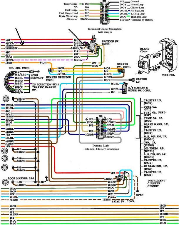
A “Gm Instrument Cluster Wiring Diagram” is a detailed schematic outlining the electrical connections and components within a vehicle’s instrument cluster. It serves as a roadmap for troubleshooting, repairs, and modifications. For instance, the wiring diagram for a 2007 Chevrolet Silverado’s instrument cluster would show the connections between the speedometer, tachometer, fuel gauge, and other gauges.
Understanding the wiring diagram is crucial for automotive technicians, enthusiasts, and DIYers. It enables them to pinpoint electrical problems, replace faulty components, and customize instrument cluster functionality. Historically, the advent of electronic instrument clusters in the 1980s introduced new complexity and the need for precise wiring diagrams.
The article will delve into the intricacies of “Gm Instrument Cluster Wiring Diagrams,” exploring their essential elements, troubleshooting techniques, and advanced applications. By delving into these diagrams, readers will gain a comprehensive understanding of instrument cluster operation and enhance their troubleshooting abilities.
In exploring “Gm Instrument Cluster Wiring Diagrams,” examining specific aspects is vital for comprehending their significance and nuances. These core elements encompass a range of dimensions, shaping the overall understanding of instrument cluster wiring diagrams in General Motors vehicles.
- Components: Displays, gauges, sensors, modules
- Connections: Wires, terminals, connectors, harnesses
- Circuitry: Electrical pathways, signal flow
- Diagnostics: Troubleshooting techniques, fault identification
- Customization: Modifications, upgrades, personalization
- Compatibility: Vehicle models, trim levels, options
- Accuracy: Precision of the diagram, up-to-date information
- Accessibility: Availability of diagrams, online sources
- Interpretation: Understanding symbols, conventions
- Safety: Precautions, electrical hazards
These aspects are interconnected, contributing to the effective utilization and comprehension of instrument cluster wiring diagrams. Accurate interpretation enables technicians to diagnose faults, customize functionality, and ensure the proper operation of instrument clusters. Understanding the circuitry and components involved enhances troubleshooting abilities, while considering compatibility ensures diagrams match specific vehicle configurations. Accessibility and safety guidelines promote efficient and responsible handling of electrical systems. By delving into these key aspects, we gain a comprehensive grasp of the intricacies of “Gm Instrument Cluster Wiring Diagrams.”
Components
Within the context of “Gm Instrument Cluster Wiring Diagrams,” the componentsdisplays, gauges, sensors, and modulesplay a critical role. The wiring diagram outlines the electrical connections and interactions between these components, enabling them to function as a cohesive unit and provide vital information to the driver.
For instance, the speedometer, a crucial gauge, relies on input from a speed sensor to accurately display vehicle speed. The wiring diagram specifies the type of sensor used, its location, and the electrical pathway between the sensor and the speedometer. Similarly, fuel level, engine temperature, and other gauges depend on specific sensors to gather data and transmit it to the appropriate display or module.
Understanding the relationship between components and the wiring diagram is essential for troubleshooting and repair. By tracing the electrical connections and identifying the specific components involved, technicians can pinpoint faults and determine whether a faulty sensor, gauge, or wiring issue is causing a malfunction. Additionally, the wiring diagram guides the installation of aftermarket components, such as upgraded gauges or performance modules, ensuring compatibility and proper functionality.
In summary, the componentsdisplays, gauges, sensors, and modulesare fundamental elements of “Gm Instrument Cluster Wiring Diagrams.” Comprehending their interconnectedness and the role of the wiring diagram in defining these connections is crucial for effective troubleshooting, customization, and overall understanding of instrument cluster operation.
Connections
The intricate web of “Connections: Wires, terminals, connectors, harnesses” forms the backbone of “Gm Instrument Cluster Wiring Diagrams,” creating a network that enables data and power transmission throughout the instrument cluster and beyond. These connections play a pivotal role in ensuring the proper functioning of all instrument cluster components, from gauges and displays to sensors and modules.
Each component within the instrument cluster relies on specific connections to perform its intended function. Wires, the fundamental carriers of electrical signals, transmit data and power between components. Terminals provide secure contact points for wires to connect to components, ensuring reliable signal transmission. Connectors, often multi-pin, facilitate connections between multiple wires and components, simplifying installation and maintenance. Harnesses, bundles of organized wires, protect individual wires from damage and organize the complex network of connections within the instrument cluster.
Understanding these connections is crucial for troubleshooting electrical faults and customizing instrument cluster functionality. By tracing the connections outlined in the wiring diagram, technicians can identify the source of electrical issues, whether it’s a loose terminal, faulty wire, or damaged connector. Additionally, when installing aftermarket components or modifying existing ones, a thorough understanding of the connections ensures compatibility and proper operation.
In summary, “Connections: Wires, terminals, connectors, harnesses” are indispensable components of “Gm Instrument Cluster Wiring Diagrams.” Their precise arrangement and reliable performance are essential for the accurate and efficient operation of instrument clusters. Comprehending these connections empowers technicians and enthusiasts to diagnose faults, customize functionality, and gain a deeper understanding of the inner workings of automotive electrical systems.
Circuitry
Within the realm of “Gm Instrument Cluster Wiring Diagrams,” “Circuitry: Electrical pathways, signal flow” holds a position of paramount importance. The intricate network of electrical pathways and the precise flow of signals through them are the lifeblood of the instrument cluster, enabling the seamless transmission of data and power throughout its various components.
The wiring diagram serves as a comprehensive roadmap, outlining the electrical pathways and signal flow within the instrument cluster. Understanding this circuitry is vital for troubleshooting electrical faults and customizing instrument cluster functionality. By tracing the flow of signals through the diagram, technicians can pinpoint the source of electrical issues, whether it’s a break in a circuit, a faulty component, or a wiring error.
Real-life examples abound, demonstrating the practical applications of understanding circuitry in “Gm Instrument Cluster Wiring Diagrams.” For instance, diagnosing a malfunctioning speedometer requires tracing the electrical pathway from the speed sensor to the speedometer gauge, identifying any disruptions in signal flow along the way. Similarly, when installing an aftermarket tachometer, the wiring diagram guides the connection of the tachometer to the appropriate signal source, ensuring accurate and reliable readings.
In essence, “Circuitry: Electrical pathways, signal flow” is the underlying foundation upon which “Gm Instrument Cluster Wiring Diagrams” are built. Comprehending this circuitry empowers technicians and enthusiasts alike to diagnose faults, customize functionality, and gain a profound understanding of the inner workings of automotive electrical systems.
Diagnostics
Within the realm of “Gm Instrument Cluster Wiring Diagrams,” “Diagnostics: Troubleshooting techniques, fault identification” stands as an indispensable pillar. The intricate connections and precise signal flow within the instrument cluster demand a systematic approach to troubleshooting faults and identifying their root causes. The wiring diagram serves as a guiding light, empowering technicians and enthusiasts alike to navigate the electrical intricacies of the instrument cluster.
When faced with an instrument cluster malfunction, the diagnostic process begins by analyzing the symptoms and understanding the affected components. The wiring diagram provides a roadmap, outlining the electrical pathways and signal flow, allowing technicians to trace potential faults. By systematically checking connections, testing components, and analyzing signal patterns, they can pinpoint the precise location and cause of the issue.
For instance, a faulty speedometer may stem from a malfunctioning speed sensor, a break in the signal wire, or a problem with the speedometer gauge itself. The wiring diagram guides the technician through the process of isolating the fault, enabling them to determine whether the issue lies within the sensor, the wiring, or the gauge. Real-life examples like these showcase the critical role of diagnostics in troubleshooting instrument cluster problems.
In summary, “Diagnostics: Troubleshooting techniques, fault identification” is an integral component of “Gm Instrument Cluster Wiring Diagrams.” Understanding the relationship between the two empowers technicians to diagnose faults accurately, repair instrument clusters effectively, and ensure the smooth operation of automotive electrical systems. It is a skill that requires patience, attention to detail, and a thorough understanding of electrical principles.
Customization
Within the realm of “Gm Instrument Cluster Wiring Diagrams,” “Customization: Modifications, upgrades, personalization” emerges as a critical aspect, empowering enthusiasts and professionals alike to tailor their vehicles’ instrument clusters to their specific needs, preferences, and performance aspirations. The “Gm Instrument Cluster Wiring Diagram” serves as the blueprint for these modifications, enabling informed decision-making and ensuring compatibility and functionality.
The cause-and-effect relationship between “Customization: Modifications, upgrades, personalization” and “Gm Instrument Cluster Wiring Diagram” is evident in the intricate connections between the instrument cluster’s components and the electrical pathways outlined in the diagram. Modifications such as gauge upgrades, custom lighting, and performance enhancements require a thorough understanding of the wiring diagram to ensure proper integration and avoid electrical issues.
Real-life examples abound, showcasing the practical applications of customization within “Gm Instrument Cluster Wiring Diagrams.” For instance, installing an aftermarket tachometer necessitates referencing the wiring diagram to identify the appropriate signal source and ensure accurate readings. Similarly, upgrading instrument cluster lighting to LEDs requires careful attention to the wiring diagram to determine compatibility and prevent overloading.
In summary, understanding the relationship between “Customization: Modifications, upgrades, personalization” and “Gm Instrument Cluster Wiring Diagram” is essential for successful modifications and enhancements. The wiring diagram provides the foundation for informed decision-making, ensuring compatibility, functionality, and a personalized driving experience. Whether seeking to enhance aesthetics, improve functionality, or optimize performance, enthusiasts and professionals alike rely on the “Gm Instrument Cluster Wiring Diagram” as their guiding light in the realm of instrument cluster customization.
Compatibility
Within the realm of “Gm Instrument Cluster Wiring Diagrams,” “Compatibility: Vehicle models, trim levels, options” emerges as a cornerstone consideration, influencing the successful implementation and functionality of instrument cluster modifications and upgrades. The wiring diagram serves as a compatibility guide, ensuring that components and features are appropriately matched to specific vehicle configurations, trim levels, and optional equipment.
- Vehicle Models: Each GM vehicle model may have unique instrument cluster configurations, requiring specific wiring diagrams tailored to the model’s electrical architecture and dashboard design. Compatibility ensures that the wiring diagram aligns with the vehicle’s make, model, and year.
- Trim Levels: Different trim levels within a vehicle model may feature variations in instrument cluster features and options. The wiring diagram must correspond with the specific trim level to ensure compatibility with additional gauges, displays, or advanced driver assistance systems.
- Options: Optional equipment, such as performance packages or technology upgrades, can introduce additional electrical components and features that require specific wiring configurations. The compatibility of the wiring diagram with the installed options ensures seamless integration and proper functioning.
- Real-Life Example: Consider upgrading the instrument cluster in a 2018 Chevrolet Silverado. The wiring diagram for a base model Silverado will differ from that of a higher trim level with an upgraded infotainment system and driver assistance features. Using the correct wiring diagram ensures compatibility and avoids potential electrical issues or malfunctioning components.
In conclusion, understanding “Compatibility: Vehicle models, trim levels, options” in relation to “Gm Instrument Cluster Wiring Diagrams” is crucial for successful modifications and upgrades. The wiring diagram serves as a compatibility roadmap, guiding users in selecting the correct diagram for their specific vehicle configuration and ensuring seamless integration of new components and features. This compatibility consideration underscores the importance of precision and attention to detail when working with electrical systems, contributing to the overall reliability and performance of the instrument cluster and the vehicle as a whole.
Accuracy
In the realm of “Gm Instrument Cluster Wiring Diagrams,” “Accuracy: Precision of the diagram, up-to-date information” stands as a cornerstone principle, directly influencing the reliability and effectiveness of instrument cluster modifications and upgrades. The wiring diagram serves as a roadmap for electrical connections and component interactions, and its accuracy is paramount for ensuring the proper functioning of the instrument cluster and the vehicle as a whole.
Accuracy encompasses two key aspects: precision of the diagram and up-to-date information. Precision refers to the meticulous attention to detail in representing the electrical connections, ensuring that each component is correctly depicted and its interactions are accurately portrayed. Up-to-date information, on the other hand, signifies that the wiring diagram reflects the latest design changes and incorporates any modifications or revisions made to the vehicle’s electrical system. This ensures that the diagram aligns with the actual configuration of the vehicle, accommodating any updates or variations.
Real-life examples abound, showcasing the practical significance of accuracy in “Gm Instrument Cluster Wiring Diagrams.” Consider a scenario where an enthusiast attempts to install an aftermarket tachometer using an outdated wiring diagram. The diagram may not accurately reflect the current electrical configuration, leading to incorrect connections and potential damage to the tachometer or other components. Conversely, a precise and up-to-date wiring diagram empowers the enthusiast to confidently make the necessary connections, ensuring the tachometer functions as intended.
In summary, “Accuracy: Precision of the diagram, up-to-date information” is a critical component of “Gm Instrument Cluster Wiring Diagrams,” influencing the success and safety of electrical modifications and upgrades. Precision ensures reliable connections, while up-to-date information guarantees compatibility with the vehicle’s current electrical configuration. Understanding the importance of accuracy empowers enthusiasts and professionals alike to navigate the complexities of instrument cluster wiring, make informed decisions, and achieve optimal performance from their vehicles.
Accessibility
In the realm of “Gm Instrument Cluster Wiring Diagrams,” “Accessibility: Availability of diagrams, online sources” plays a pivotal role, fostering a symbiotic relationship between the availability of information and the effective utilization of wiring diagrams. Accessibility directly influences the ease with which technicians, enthusiasts, and DIYers can obtain, comprehend, and apply these diagrams, ultimately impacting the quality and efficiency of instrument cluster repairs, modifications, and upgrades.
The availability of wiring diagrams in various formats, including online sources, has revolutionized access to this critical information. Websites, forums, and online databases provide a wealth of wiring diagrams, catering to a wide range of GM vehicle models and years. This accessibility empowers individuals to troubleshoot electrical issues, customize instrument clusters, and enhance their vehicles’ performance without the need for costly dealership visits or specialized tools.
Real-life examples abound, showcasing the practical applications of wiring diagram accessibility. Consider a scenario where a technician encounters a malfunctioning speedometer in a 2015 Chevrolet Silverado. By accessing the wiring diagram online, the technician can quickly identify the potential causes, such as a faulty speed sensor or a break in the signal wire. Armed with this information, the technician can efficiently diagnose and resolve the issue, saving time and resources.
Moreover, the accessibility of wiring diagrams fosters a collaborative environment within the automotive community. Online forums and discussion boards allow enthusiasts to share their knowledge, experiences, and insights related to instrument cluster wiring. This exchange of information contributes to a collective understanding of electrical systems, enabling individuals to learn from others’ successes and troubleshoot complex issues more effectively.
In summary, “Accessibility: Availability of diagrams, online sources” is a critical component of “Gm Instrument Cluster Wiring Diagrams,” providing a direct link between information and application. The widespread availability of wiring diagrams empowers individuals to maintain, modify, and enhance their vehicles, fostering a culture of self-reliance and technical proficiency. Understanding this connection is essential for anyone seeking to navigate the intricacies of automotive electrical systems and achieve optimal performance from their vehicles.
Interpretation
In the realm of “Gm Instrument Cluster Wiring Diagrams,” “Interpretation: Understanding symbols, conventions” emerges as a cornerstone skill, enabling individuals to decipher the complex language of electrical schematics. It involves comprehending the standardized symbols and conventions used to represent electrical components, their connections, and the flow of signals throughout the instrument cluster.
-
Symbol Recognition
Wiring diagrams employ a standardized set of symbols to represent various electrical components, such as resistors, transistors, and diodes. Understanding these symbols is crucial for identifying and locating specific components within the circuit.
-
Circuit Notation
Wiring diagrams utilize a specific notation to indicate the connections between components. Lines represent wires, while dots and junctions denote connection points. Interpreting this notation accurately is essential for tracing signal paths and troubleshooting electrical issues.
-
Color Coding
In many wiring diagrams, wires are color-coded to indicate their function or purpose. Understanding these color codes simplifies the process of identifying and tracing wires, expediting the diagnosis and repair of electrical faults.
-
Connector Identification
Wiring diagrams also include symbols to represent electrical connectors. These symbols provide information about the type of connector, the number of pins it has, and its location within the vehicle. Accurate interpretation of connector symbols ensures proper mating and connection of electrical components.
Mastering “Interpretation: Understanding symbols, conventions” empowers individuals to effectively navigate the complexities of “Gm Instrument Cluster Wiring Diagrams.” It enables them to identify and locate components, trace signal paths, troubleshoot electrical issues, and make informed decisions regarding instrument cluster modifications and repairs. This understanding forms the foundation for successful electrical work, ensuring the proper functioning and reliability of the instrument cluster and the vehicle as a whole.
Safety
In the realm of “Gm Instrument Cluster Wiring Diagrams,” “Safety: Precautions, electrical hazards” stands as a critical aspect, demanding utmost attention to ensure the well-being of individuals working with electrical systems. Understanding these precautions and hazards is paramount for preventing electrical accidents, protecting components, and maintaining the integrity of the instrument cluster and the vehicle as a whole.
-
Electrical Shock Hazard
Working with electrical circuits poses the risk of electrical shock, which can cause serious injury or even death. Proper safety measures, such as using insulated tools, wearing protective gear, and ensuring proper grounding, are essential to minimize this hazard.
-
Short Circuit Risk
Accidental contact between wires or components can create a short circuit, leading to excessive current flow and potentially causing fires or damage to electrical components. Careful attention to wire insulation and proper connections is crucial for preventing short circuits.
-
Fire Hazard
Electrical faults or excessive current draw can result in fires, posing a significant safety risk. Understanding the electrical load capacity of components and using appropriate fuses or circuit breakers is essential for preventing fires.
-
Electrostatic Discharge (ESD)
Electrostatic discharge can damage sensitive electronic components within the instrument cluster. Proper grounding techniques and the use of anti-static materials are necessary to minimize the risk of ESD.
Observing these safety precautions and being aware of the potential electrical hazards associated with “Gm Instrument Cluster Wiring Diagrams” is crucial for ensuring a safe working environment, preventing accidents, and maintaining the reliability and functionality of the instrument cluster. Neglecting these precautions can have severe consequences, emphasizing the importance of safety as a top priority when working with electrical systems.


Related Posts


