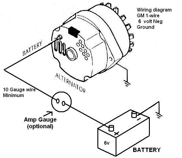
A Gm 1 Wire Alternator Wiring Diagram is a schematic representation of the electrical connections required to install and operate a GM 1-wire alternator. These alternators are commonly found in automotive applications and provide a straightforward wiring configuration, requiring only one wire connection to function. For instance, a typical 1-wire alternator wiring diagram involves connecting the alternator’s output terminal directly to the vehicle’s battery positive terminal, allowing it to charge the battery and power electrical systems.
The benefits of using a 1-wire alternator wiring diagram include its simplicity, ease of installation, and ability to self-regulate the charging voltage. Historically, the development of 1-wire alternators was a significant advancement, as it eliminated the need for complex wiring harnesses and external voltage regulators. The single-wire design simplified alternator installations, making them more accessible to DIY enthusiasts and automotive professionals.
In this article, we will delve deeper into the intricacies of Gm 1 Wire Alternator Wiring Diagrams, exploring their components, wiring configurations, and troubleshooting techniques. Our aim is to provide a comprehensive guide that empowers readers to understand and implement these diagrams effectively, ensuring optimal charging system performance.
Understanding the essential aspects of Gm 1 Wire Alternator Wiring Diagrams is crucial for proper installation, operation, and troubleshooting of automotive charging systems. These diagrams provide a visual representation of the electrical connections required to connect a 1-wire alternator to the vehicle’s electrical system.
- Components: Alternator, battery, wiring
- Connections: Single wire from alternator to battery positive terminal
- Voltage Regulation: Self-regulating alternator maintains consistent charging voltage
- Simplicity: Easy to install and maintain, suitable for DIY enthusiasts
- Efficiency: Single-wire design minimizes power loss
- Reliability: Durable and dependable alternator performance
- Troubleshooting: Simple diagnostics based on voltage and continuity checks
- Compatibility: Compatible with various vehicle makes and models
- Safety: Proper wiring ensures safe operation and prevents electrical hazards
These aspects are interconnected and play vital roles in the functionality of Gm 1 Wire Alternator Wiring Diagrams. For instance, the self-regulating alternator maintains the charging voltage within a safe range, protecting the battery and electrical components from overcharging or undercharging. The single-wire design simplifies the installation process, making it accessible to individuals with limited electrical experience. Proper troubleshooting techniques, based on voltage and continuity checks, enable quick identification and resolution of any issues that may arise.
Components
Within the context of a Gm 1 Wire Alternator Wiring Diagram, the componentsalternator, battery, and wiringplay critical roles in the system’s functionality. The alternator serves as the heart of the charging system, generating electrical power to recharge the battery and supply electricity to the vehicle’s electrical components. The battery stores the generated electrical energy, providing a reserve of power when the alternator is not operating. The wiring, including the single wire connection from the alternator to the battery, forms the electrical pathway for current flow, ensuring that the charging system operates efficiently.
The relationship between these components is interdependent. The alternator relies on the battery to provide an initial excitation current, which triggers the alternator’s magnetic field and initiates the generation of electricity. In turn, the alternator maintains the battery’s charge, preventing it from discharging and ensuring a consistent power supply to the vehicle. The wiring, by connecting these components, completes the circuit, allowing the flow of electrical current and the proper functioning of the charging system.
Understanding the connection between the components in a Gm 1 Wire Alternator Wiring Diagram is essential for troubleshooting and maintenance purposes. For instance, if the alternator fails to charge the battery, it could indicate a problem with the alternator itself, the wiring connections, or even the battery. By analyzing the relationship between these components and their respective functions, technicians can systematically diagnose and resolve issues within the charging system.
Connections
In the context of a Gm 1 Wire Alternator Wiring Diagram, the single wire connection from the alternator to the battery positive terminal plays a pivotal role in the system’s functionality. This direct connection establishes the electrical pathway for the charging current to flow from the alternator, through the wiring, and into the battery for storage and distribution throughout the vehicle’s electrical system.
The significance of this single wire connection lies in its simplicity and effectiveness. Unlike conventional alternator wiring diagrams that require multiple wires for excitation, voltage regulation, and grounding, the 1-wire design simplifies the installation and maintenance process. This single wire connection carries both the excitation current and the charging current, eliminating the need for complex wiring harnesses and external voltage regulators.
In real-life applications, the single wire connection in a Gm 1 Wire Alternator Wiring Diagram is commonly implemented using a heavy-gauge wire, such as 8 or 10 AWG, to handle the high current flow. The wire is typically connected to the alternator’s output terminal and the battery’s positive terminal using ring terminals or spade connectors, ensuring a secure and reliable connection.
Understanding the critical role of the single wire connection in a Gm 1 Wire Alternator Wiring Diagram is essential for troubleshooting and maintenance purposes. If the connection is loose, damaged, or corroded, it can cause charging problems, such as insufficient battery charging or alternator overcharging. By recognizing the importance of this connection and its impact on the charging system, technicians can effectively diagnose and resolve issues to ensure optimal performance.
Voltage Regulation
Within the context of a Gm 1 Wire Alternator Wiring Diagram, the self-regulating alternator plays a critical role in maintaining a consistent charging voltage for the vehicle’s electrical system. This voltage regulation ensures that the battery receives an appropriate charging current to meet its needs and prevents overcharging or undercharging, which can damage the battery and other electrical components.
The self-regulating alternator achieves voltage regulation through an internal voltage regulator. This regulator monitors the voltage output of the alternator and adjusts the excitation current accordingly. As the electrical load on the vehicle increases, the voltage regulator increases the excitation current, leading to a higher charging voltage to meet the increased demand. Conversely, when the electrical load decreases, the voltage regulator reduces the excitation current, resulting in a lower charging voltage.
Real-life examples of the importance of voltage regulation in a Gm 1 Wire Alternator Wiring Diagram can be seen in various scenarios. For instance, when starting the vehicle, the electrical load is high due to the engagement of the starter motor and other systems. The self-regulating alternator responds by increasing the charging voltage to ensure that the battery receives sufficient current to start the engine and power the electrical accessories.
Understanding the connection between voltage regulation and Gm 1 Wire Alternator Wiring Diagrams is crucial for automotive technicians and enthusiasts alike. It enables them to diagnose and troubleshoot charging system issues effectively. For example, if the battery is not receiving an adequate charging voltage, it could indicate a problem with the voltage regulator or other components in the charging system.
Simplicity
Within the realm of Gm 1 Wire Alternator Wiring Diagrams, the concept of simplicity holds immense relevance, as it underscores the ease of installation and maintenance, rendering it suitable even for DIY enthusiasts. This characteristic stems from several key factors, each contributing to an overall user-friendly experience.
- Minimal Components: Unlike conventional alternator wiring diagrams that require a plethora of wires, voltage regulators, and other components, the 1-wire alternator system simplifies the setup by minimizing the number of necessary parts. This reduces the complexity of the installation process.
- Straightforward Wiring: The single-wire design eliminates the need for complex wiring harnesses and intricate connections. The straightforward wiring scheme makes it easier for individuals to understand and implement, reducing the likelihood of errors during installation.
- Self-Regulating Alternator: The self-regulating alternator eliminates the need for external voltage regulators, further simplifying the overall system. This reduces the number of components that require maintenance and potential troubleshooting.
- DIY-Friendly Maintenance: With its reduced complexity, the Gm 1 Wire Alternator Wiring Diagram empowers DIY enthusiasts to perform maintenance tasks. Basic electrical knowledge and tools are sufficient to handle tasks such as wire inspection, connection tightening, and alternator replacement.
In summary, the simplicity of Gm 1 Wire Alternator Wiring Diagrams manifests in its minimal components, straightforward wiring, self-regulating alternator, and DIY-friendly nature. This user-centric design makes it an accessible and practical solution for both professional technicians and automotive enthusiasts.
Efficiency
Within the realm of Gm 1 Wire Alternator Wiring Diagrams, the concept of efficiency takes center stage. The single-wire design inherent to these diagrams plays a crucial role in minimizing power loss, a factor of paramount importance in automotive electrical systems.
- Reduced Resistance: The single-wire configuration eliminates multiple connections, reducing the overall resistance in the circuit. Lower resistance minimizes voltage drop, ensuring efficient power transfer from the alternator to the battery.
- Optimized Current Flow: The direct connection between the alternator and the battery allows for unobstructed current flow. This streamlined path reduces energy dissipation and enhances the alternator’s ability to charge the battery effectively.
- Lower Heat Generation: Reduced resistance and optimized current flow result in less heat generation within the wiring. This translates to improved system reliability and extended component lifespan.
- Fuel Economy: By minimizing power loss, the single-wire design contributes to improved fuel economy. Efficient charging of the battery reduces the load on the alternator, freeing up engine power that would otherwise be diverted to power generation.
In conclusion, the efficiency of Gm 1 Wire Alternator Wiring Diagrams stems from the single-wire design’s ability to reduce resistance, optimize current flow, minimize heat generation, and enhance fuel economy. These factors collectively contribute to a more efficient and reliable charging system, ensuring optimal performance and longevity of the vehicle’s electrical components.
Reliability
In the realm of Gm 1 Wire Alternator Wiring Diagrams, the aspect of reliability holds immense significance, directly linked to the durable and dependable performance of the alternator. This unwavering performance stems from several key factors, each contributing to the longevity and efficiency of the charging system.
The single-wire design plays a pivotal role in enhancing reliability. By eliminating multiple connections and complex wiring harnesses, the risk of loose connections, corrosion, and other electrical faults is significantly reduced. This simplified design ensures a more robust and stable charging system, minimizing the likelihood of alternator failures.
Moreover, the self-regulating alternator, a cornerstone of the 1-wire design, contributes to reliability. It eliminates the need for external voltage regulators, which are prone to failure due to environmental factors or voltage spikes. The internal voltage regulation mechanism ensures consistent charging voltage, protecting the battery from overcharging or undercharging, both of which can lead to premature battery failure.
In practical applications, the reliability of Gm 1 Wire Alternator Wiring Diagrams translates to peace of mind for vehicle owners. With a durable and dependable alternator, drivers can embark on long journeys or navigate challenging driving conditions without the worry of electrical system failures. This reliability also reduces maintenance costs and extends the lifespan of the charging system, contributing to overall vehicle longevity.
In summary, the connection between reliability and Gm 1 Wire Alternator Wiring Diagrams is inextricably linked. The durable and dependable performance of the alternator, enabled by the single-wire design and self-regulating alternator, ensures a robust and stable charging system. This reliability translates to reduced maintenance costs, extended component lifespan, and peace of mind for vehicle owners, solidifying the 1-wire alternator wiring diagram as a reliable solution for automotive electrical systems.
Troubleshooting
Within the context of Gm 1 Wire Alternator Wiring Diagrams, troubleshooting plays a critical role in maintaining a functional charging system. Simple diagnostics based on voltage and continuity checks empower individuals to pinpoint issues and restore proper alternator operation.
One key aspect of troubleshooting Gm 1 Wire Alternator Wiring Diagrams is understanding the relationship between voltage and continuity. Voltage checks measure the electrical potential at various points in the circuit, while continuity checks assess the integrity of the wiring and connections. By combining these checks, technicians can isolate problems and determine whether the issue originates from the alternator, wiring, or battery.
Real-life examples showcase the practical applications of these troubleshooting techniques. For instance, if an alternator fails to charge the battery, a voltage check at the alternator output terminal can indicate a faulty alternator or a problem with the wiring. Continuity checks along the wiring harness can identify breaks or loose connections that disrupt current flow.
Understanding the connection between troubleshooting and Gm 1 Wire Alternator Wiring Diagrams enables technicians to perform efficient diagnostics. By utilizing simple voltage and continuity checks, they can quickly identify and resolve issues, ensuring a reliable charging system. This understanding empowers individuals to maintain their vehicles and avoid costly repairs.
Compatibility
Within the realm of Gm 1 Wire Alternator Wiring Diagrams, the aspect of compatibility plays a pivotal role, as it determines the applicability of the diagram across a wide range of vehicle makes and models.
- Universal Design: Gm 1 Wire Alternator Wiring Diagrams adhere to universal electrical principles, making them compatible with various alternator makes and models. This versatility simplifies the selection and installation process, allowing technicians to use a single diagram for multiple vehicles.
- Adaptable Wiring: The single-wire design enables easy adaptation to different vehicle electrical systems. By adjusting wire gauge and length, the diagram can be tailored to meet specific vehicle requirements, ensuring a proper fit and reliable charging performance.
- OEM Compatibility: Many Gm 1 Wire Alternator Wiring Diagrams are designed to be compatible with original equipment (OEM) alternators. This compatibility ensures seamless integration with existing vehicle systems, preserving factory-installed features and maintaining optimal charging efficiency.
- Aftermarket Options: The compatibility extends to aftermarket alternators, providing vehicle owners with a wider range of choices. Whether upgrading to a higher-output alternator or replacing a faulty one, the single-wire design allows for easy integration of aftermarket components.
In summary, the compatibility of Gm 1 Wire Alternator Wiring Diagrams offers numerous advantages. Universal design, adaptable wiring, OEM compatibility, and aftermarket options empower technicians and vehicle owners with a versatile solution that simplifies alternator installations, ensures reliable charging performance, and caters to a diverse range of vehicle makes and models.
Safety
Within the context of Gm 1 Wire Alternator Wiring Diagrams, safety is of paramount importance. Proper wiring practices are essential to ensure safe operation and prevent electrical hazards that could compromise the vehicle’s electrical system and pose risks to both the vehicle and its occupants.
Electrical hazards can arise from various factors, including loose connections, damaged wiring, or incorrect installation. These hazards can manifest in the form of electrical fires, shorts, or power surges, which can cause extensive damage to electrical components and even lead to personal injury. Gm 1 Wire Alternator Wiring Diagrams play a critical role in mitigating these risks by providing a clear and concise roadmap for proper wiring.
Real-life examples underscore the importance of safety in Gm 1 Wire Alternator Wiring Diagrams. For instance, consider a scenario where an alternator is improperly wired, resulting in a loose connection. This loose connection could generate excessive heat, potentially igniting surrounding components and causing an electrical fire. By adhering to the guidelines outlined in the wiring diagram, technicians can ensure that all connections are secure and properly insulated, eliminating the risk of such hazards.
The practical applications of understanding the connection between safety and Gm 1 Wire Alternator Wiring Diagrams extend beyond preventing electrical hazards. Proper wiring also contributes to optimal alternator performance and longevity. By following the recommended wiring practices, technicians can minimize voltage drop and ensure efficient power transfer, maximizing the alternator’s output and extending its lifespan.
In summary, safety is an integral aspect of Gm 1 Wire Alternator Wiring Diagrams. Proper wiring practices outlined in these diagrams are essential to prevent electrical hazards, ensuring the safe operation of the vehicle’s electrical system. Understanding and adhering to these guidelines empower technicians to perform accurate and reliable alternator installations, safeguarding against potential risks and maximizing the performance and longevity of the charging system.


![[DIAGRAM] Wiring Diagram For 1 Wire Gm Alternator](https://i0.wp.com/capestarter.com/ESW/Files/2wire12volt.jpg?w=665&ssl=1)


Related Posts


