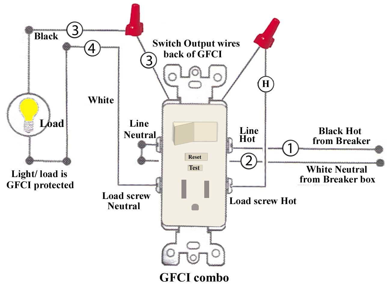
A GFCI wiring diagram with a switch is a schematic drawing that shows the proper electrical connections for a ground fault circuit interrupter (GFCI) outlet or breaker with an integrated switch. GFCIs are safety devices that protect users from electrical shocks by tripping the circuit when an imbalance is detected between the current flowing through the hot and neutral wires.
GFCIs are required by code in many locations, such as bathrooms, kitchens, and outdoor areas, where there is a risk of electrical shock due to moisture or water. Wiring a GFCI with a switch can be more complex than wiring a standard outlet or switch, but it is important to follow the manufacturer’s instructions carefully to ensure proper operation and safety.
This article will provide a detailed guide to wiring a GFCI outlet with a switch, including wiring diagrams and step-by-step instructions. We will also discuss the benefits and limitations of GFCIs and provide troubleshooting tips.
Ground fault circuit interrupters (GFCIs) are an essential safety device in any electrical system. They protect users from electrical shocks by tripping the circuit when an imbalance is detected between the current flowing through the hot and neutral wires. GFCIs are required by code in many locations, such as bathrooms, kitchens, and outdoor areas, where there is a risk of electrical shock due to moisture or water.
- Protection: GFCIs provide protection from electrical shocks.
- Required by code: GFCIs are required in many locations by electrical codes.
- Wiring: GFCIs can be wired with or without a switch.
- Receptacles: GFCI receptacles are available in a variety of configurations.
- Breakers: GFCI breakers can be used to protect an entire circuit.
- Testing: GFCIs should be tested regularly to ensure proper operation.
- Troubleshooting: GFCIs can be tripped by a variety of factors.
- Safety: GFCIs are an important safety device that can help to prevent electrical shocks.
- Convenience: GFCIs with switches can be used to control power to a receptacle.
GFCIs are a relatively simple device, but they can be a lifesaver in the event of an electrical fault. By understanding the basics of GFCI wiring diagrams with switches, you can help to ensure the safety of your home and family.
Protection
Electrical shocks can be dangerous and even life-threatening. GFCIs are an important safety device that can help to protect you from electrical shocks. They are required by code in many locations, such as bathrooms, kitchens, and outdoor areas, where there is a risk of electrical shock due to moisture or water.
- Grounding: GFCIs work by comparing the current flowing through the hot and neutral wires. If there is an imbalance, it means that some of the current is leaking to ground. This can be caused by a faulty appliance, a damaged cord, or even a wet surface. When a GFCI detects an imbalance, it trips the circuit, cutting off the power and preventing an electrical shock.
- Testing: GFCIs should be tested regularly to ensure that they are working properly. This can be done by pressing the “test” button on the GFCI. The GFCI should trip, and the power should be cut off.
- Maintenance: GFCIs can last for many years, but they may need to be replaced if they are damaged or if they start to trip frequently. It is important to have a qualified electrician inspect and replace GFCIs as needed.
- Safety: GFCIs are an important safety device that can help to protect you from electrical shocks. By understanding how GFCIs work and how to test and maintain them, you can help to ensure your safety and the safety of your family.
GFCIs are a relatively simple device, but they can be a lifesaver in the event of an electrical fault. By understanding the basics of GFCI wiring diagrams with switches, you can help to ensure the safety of your home and family.
Required by code
In the context of GFCI wiring diagrams with switches, it is important to understand the code requirements for GFCI installation. Electrical codes are in place to ensure the safety of electrical installations and to minimize the risk of electrical shocks and fires. GFCIs are required in many locations by electrical codes, and it is important to be aware of these requirements when designing and installing electrical systems.
- Bathrooms: GFCIs are required in all bathrooms, regardless of the presence of a bathtub or shower. This is because bathrooms are often damp or wet, which can increase the risk of electrical shock.
- Kitchens: GFCIs are required in all kitchens, within 6 feet of the sink. This is because kitchens are often wet or damp, and there is a risk of electrical shock from appliances such as toasters and blenders.
- Outdoor areas: GFCIs are required in all outdoor areas, such as patios, decks, and balconies. This is because outdoor areas are often exposed to moisture and water, which can increase the risk of electrical shock.
- Garages and workshops: GFCIs are required in all garages and workshops. This is because garages and workshops are often damp or wet, and there is a risk of electrical shock from tools and equipment.
It is important to note that these are just a few of the locations where GFCIs are required by electrical codes. There may be other locations where GFCIs are required, depending on the specific code requirements in your area. It is always best to consult with a qualified electrician to ensure that your electrical system is up to code and that all required GFCIs are installed.
Wiring
The ability to wire GFCIs with or without a switch is a critical component of GFCI wiring diagrams with switches. This is because it allows for a variety of different configurations, depending on the specific needs of the application. For example, in some cases it may be desirable to have a GFCI outlet that is controlled by a switch, while in other cases it may be preferable to have a GFCI outlet that is always on.
When a GFCI is wired with a switch, the switch controls the power to the GFCI outlet. This means that the GFCI outlet will only be powered when the switch is turned on. This can be useful in situations where it is desirable to be able to turn off the power to the GFCI outlet, such as when servicing or replacing the GFCI outlet. It can also be useful in situations where it is desirable to be able to control the power to the GFCI outlet from a remote location, such as from a light switch or timer.
When a GFCI is wired without a switch, the GFCI outlet is always powered. This means that the GFCI outlet will be protected from electrical shocks even when the switch is turned off. This can be useful in situations where it is important to have the GFCI outlet protected from electrical shocks at all times, such as in bathrooms or kitchens.
Understanding the relationship between “Wiring: GFCIs can be wired with or without a switch.” and “Gfci Wiring Diagram With Switch” is important for designing and installing electrical systems. By understanding the different wiring configurations that are available, it is possible to choose the best configuration for the specific needs of the application.
Receptacles
One important aspect of GFCI wiring diagrams with switches is the variety of configurations available for GFCI receptacles. GFCI receptacles are available in a variety of configurations, including:
- Standard GFCI receptacles: These are the most common type of GFCI receptacle, and they provide protection from electrical shocks for a single outlet.
- Combination GFCI/AFCI receptacles: These receptacles provide protection from both electrical shocks and arc faults. Arc faults are a type of electrical fault that can occur when there is a loose connection in an electrical circuit, and they can be a fire hazard.
- Weather-resistant GFCI receptacles: These receptacles are designed to be used in outdoor locations, and they are resistant to moisture and weather damage.
- Tamper-resistant GFCI receptacles: These receptacles have a special design that makes it difficult for children to insert objects into the slots, which can help to prevent electrical shocks.
The type of GFCI receptacle that is used will depend on the specific needs of the application. For example, a standard GFCI receptacle may be sufficient for a bathroom outlet, while a weather-resistant GFCI receptacle may be required for an outdoor outlet.
When choosing a GFCI receptacle, it is important to consider the following factors:
- The location of the outlet: The location of the outlet will determine the type of GFCI receptacle that is required. For example, a weather-resistant GFCI receptacle is required for outdoor outlets.
- The type of appliances that will be plugged into the outlet: The type of appliances that will be plugged into the outlet will determine the amperage rating of the GFCI receptacle that is required.
- The presence of children: If there are children in the home, it is important to choose a GFCI receptacle that is tamper-resistant.
By understanding the different configurations of GFCI receptacles that are available, it is possible to choose the right receptacle for the specific needs of the application.
Breakers
In the context of “Gfci Wiring Diagram With Switch”, understanding the role of GFCI breakers in protecting an entire circuit is crucial. GFCI breakers offer a comprehensive approach to electrical safety, and their integration with switch wiring diagrams enhances the overall protection strategy.
- Circuit-wide Protection: GFCI breakers provide protection to all outlets and appliances connected to the circuit they are installed on. Unlike GFCI receptacles, which protect individual outlets, GFCI breakers extend protection to the entire circuit, ensuring a broader safeguard.
- Cost-effective Solution: Installing a single GFCI breaker can be more cost-effective compared to installing multiple GFCI receptacles throughout a circuit. It simplifies the protection scheme and reduces the number of devices requiring maintenance.
- Enhanced Convenience: GFCI breakers offer the convenience of centralized protection. If a fault occurs anywhere in the circuit, the GFCI breaker trips, eliminating the need to locate and reset individual GFCI receptacles.
- Code Compliance: In many jurisdictions, electrical codes require GFCI protection for specific areas such as bathrooms, kitchens, and outdoor locations. GFCI breakers provide a compliant solution, meeting code requirements and ensuring safety.
By incorporating GFCI breakers into “Gfci Wiring Diagram With Switch”, the protection against electrical hazards is extended to the entire circuit, providing a comprehensive and cost-effective approach to electrical safety. This integration enhances the reliability and safety of electrical systems, safeguarding against potential electrical shocks and ensuring peace of mind.
Testing
Within the context of “Gfci Wiring Diagram With Switch”, testing GFCIs regularly is a crucial aspect for maintaining electrical safety and ensuring the proper functioning of the circuit. Regular testing helps identify any potential issues or deterioration in the GFCI’s performance, allowing for timely corrective actions to prevent electrical hazards.
- Frequency of Testing: GFCIs should be tested monthly or as per the manufacturer’s recommendations. Consistent testing ensures ongoing protection and reduces the risk of electrical shocks.
- Test Button: Most GFCIs have a built-in test button that simulates a ground fault condition. Pressing the test button should trip the GFCI, indicating proper operation. If the GFCI fails to trip, it should be replaced.
- Reset Button: After testing, the GFCI needs to be reset to restore power. If the GFCI trips frequently without any apparent fault, it may indicate a problem with the GFCI or the circuit wiring, requiring further investigation.
- Visual Inspection: Regularly inspect the GFCI for any signs of damage, such as cracks, discoloration, or loose connections. A damaged GFCI should be replaced immediately to maintain electrical safety.
By incorporating regular testing into the “Gfci Wiring Diagram With Switch”, homeowners and electricians can proactively ensure the reliability and safety of the electrical system. Proper testing practices contribute to the prevention of electrical accidents, safeguarding occupants and property.
Troubleshooting
Within the context of “Gfci Wiring Diagram With Switch”, understanding the factors that can trip GFCIs is crucial for effective troubleshooting and maintaining electrical safety. GFCIs are designed to trip when they detect an imbalance in the current flowing through the hot and neutral wires, indicating a potential electrical fault or hazard.
Common causes of GFCI trips include:
- Ground faults: This occurs when current leaks from the hot wire to the ground wire or any other unintended path, creating an imbalance that trips the GFCI.
- Overloads: When the total current draw on a circuit exceeds the capacity of the GFCI, it trips to prevent overheating and potential fire hazards.
- Damaged GFCI: A faulty GFCI may trip even without any actual electrical fault, requiring replacement.
- Loose connections: Poor connections in the wiring or at the GFCI terminals can lead to intermittent tripping.
Troubleshooting GFCIs involves identifying the underlying cause of the trip and taking appropriate corrective actions. This may include checking for ground faults using a multimeter, addressing overloads by reducing the load on the circuit, replacing a faulty GFCI, or tightening loose connections. Correctly interpreting the GFCI’s behavior and understanding the potential causes of tripping are essential for effective troubleshooting.
By incorporating troubleshooting techniques into “Gfci Wiring Diagram With Switch”, electricians and homeowners can diagnose and resolve GFCI issues promptly, ensuring the safety and proper functioning of the electrical system.
Safety
GFCIs (Ground Fault Circuit Interrupters) play a critical role in electrical safety, and their integration into “Gfci Wiring Diagram With Switch” is essential for ensuring the protection of individuals from electrical hazards. GFCIs are designed to detect imbalances in the current flowing through the hot and neutral wires, which can indicate a potential electrical fault or leakage. When such an imbalance is detected, the GFCI swiftly trips, interrupting the circuit and preventing the flow of electricity, thereby safeguarding against electrical shocks.
The connection between “Safety: GFCIs are an important safety device that can help to prevent electrical shocks.” and “Gfci Wiring Diagram With Switch” is evident in the fact that GFCIs form an integral part of the wiring diagram. The diagram outlines the proper installation and connection of GFCIs within an electrical system, ensuring that they are positioned at strategic points to provide maximum protection. Electricians and homeowners rely on these diagrams to correctly wire GFCIs, ensuring their effectiveness in preventing electrical accidents.
A practical example of the importance of “Safety: GFCIs are an important safety device that can help to prevent electrical shocks.” within “Gfci Wiring Diagram With Switch” can be seen in bathrooms and kitchens, where the risk of electrical shock is higher due to the presence of water and electrical appliances. GFCIs are required by electrical codes in these areas to protect against potential hazards arising from faulty appliances or accidental contact with water. By incorporating GFCIs into the wiring diagram, electricians ensure that these spaces are equipped with the necessary safety measures to prevent electrical shocks.
Understanding the connection between “Safety: GFCIs are an important safety device that can help to prevent electrical shocks.” and “Gfci Wiring Diagram With Switch” enables individuals to appreciate the critical role of GFCIs in safeguarding against electrical hazards. This understanding empowers them to make informed decisions regarding electrical safety measures in their homes and workplaces, contributing to a safer electrical environment for all.
Convenience
The integration of switches into GFCI (Ground Fault Circuit Interrupter) wiring diagrams offers a unique advantage in terms of convenience and control over electrical circuits. GFCIs are essential safety devices that protect against electrical shocks by detecting imbalances in current flow, but incorporating switches into their design adds an extra layer of functionality and flexibility to electrical systems.
A GFCI with a switch allows users to conveniently control the power supply to a particular receptacle or group of receptacles. This feature is particularly useful in situations where appliances or devices need to be turned off or isolated for maintenance, repairs, or energy conservation. For example, in a bathroom, a GFCI with a switch can be installed to control the power to a hair dryer or other appliances, allowing users to easily turn them off when not in use.
The wiring diagram for a GFCI with a switch is slightly more complex than a standard GFCI, but it provides the added functionality of switch control. The switch is typically wired in series with the GFCI, allowing it to interrupt the power supply when turned off. This arrangement ensures that the GFCI’s protective function remains active even when the switch is turned off, providing continuous protection against electrical hazards.
Understanding the connection between “Convenience: GFCIs with switches can be used to control power to a receptacle.” and “Gfci Wiring Diagram With Switch” is crucial for electricians and homeowners alike. It enables them to design and install electrical systems that are both safe and convenient, meeting the specific needs of different applications. By incorporating GFCIs with switches into their wiring diagrams, they can provide users with the ability to easily control power to receptacles, enhancing safety and convenience in various settings.


Related Posts


