A Gas Club Car Ignition Switch Wiring Diagram is a visual representation of the electrical connections between the ignition switch and other components in a gas-powered Club Car golf cart. It serves as a guide for troubleshooting electrical problems and ensuring the proper functioning of the ignition system.
By providing a clear layout of the wiring connections, the diagram enables technicians and users to trace circuits, identify faulty components, and restore electrical functionality. Its importance lies in ensuring a safe and reliable ignition system, preventing potential hazards and ensuring the efficient operation of the golf cart.
Historically, ignition switch wiring diagrams have evolved alongside the development of electrical systems in vehicles. Early designs used simple diagrams with basic connections, while modern ones incorporate more complex circuitry to accommodate additional features and safety mechanisms.
Understanding the key aspects of a Gas Club Car Ignition Switch Wiring Diagram is essential for diagnosing and resolving ignition-related issues. These diagrams provide a comprehensive overview of the electrical connections within the ignition system, enabling technicians and users to identify faulty components, trace circuits, and ensure the proper functioning of the gas-powered Club Car golf cart.
- Electrical Connections: Diagrams depict the precise wiring connections between the ignition switch, battery, starter solenoid, and other electrical components.
- Circuit Tracing: They allow technicians to trace the flow of electrical current through the ignition system, aiding in the identification of open or short circuits.
- Component Identification: Diagrams clearly label each component within the ignition system, making it easy to locate and replace faulty parts.
- Troubleshooting: Diagrams serve as a valuable tool for troubleshooting ignition problems, providing a visual representation of the system for quick and accurate diagnosis.
- Safety: Ensuring proper electrical connections and component functionality enhances the overall safety of the golf cart’s operation.
- Maintenance: Diagrams facilitate regular maintenance tasks, such as spark plug replacement or battery inspection, by providing a clear understanding of the ignition system layout.
- Customization: For those looking to customize their golf carts, diagrams enable modifications to the ignition system, such as installing additional accessories or upgrading components.
- Performance Optimization: By optimizing electrical connections and ensuring proper ignition timing, diagrams contribute to improved engine performance and efficiency.
- Historical Significance: Ignition switch wiring diagrams have evolved alongside the development of electrical systems in vehicles, reflecting advancements in technology and safety features.
These key aspects highlight the importance of Gas Club Car Ignition Switch Wiring Diagrams in maintaining, diagnosing, and optimizing the ignition system. They provide a visual framework for understanding the electrical connections, tracing circuits, identifying faulty components, and troubleshooting issues. By utilizing these diagrams, technicians and users can ensure the safe and reliable operation of their gas-powered Club Car golf carts.
Electrical Connections
Within the context of Gas Club Car Ignition Switch Wiring Diagrams, understanding the electrical connections is paramount. These diagrams provide a visual representation of the intricate network of wires that connect the ignition switch to other crucial components, ensuring the smooth operation of the golf cart.
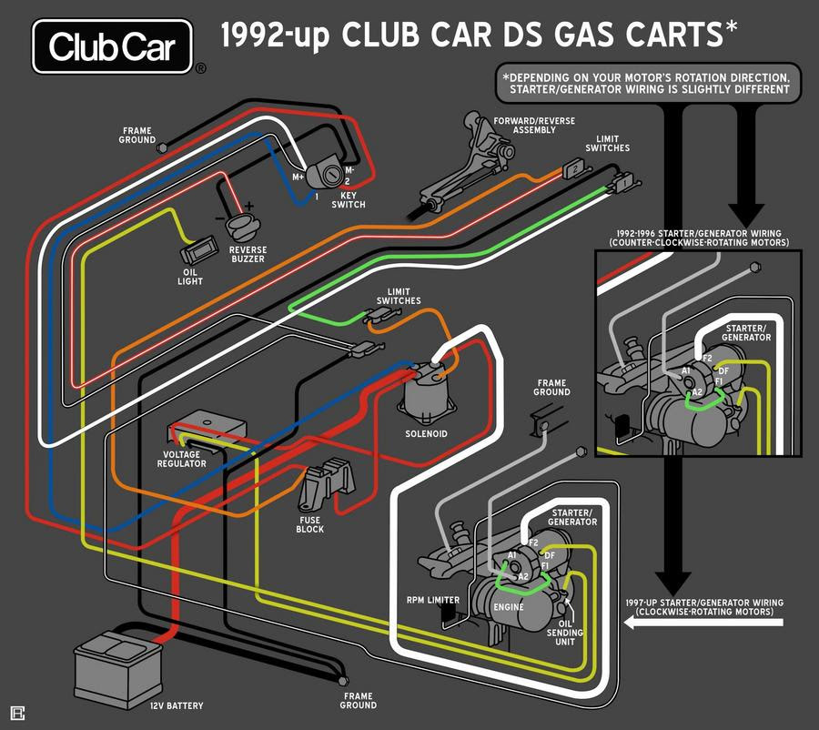
- Battery Connection: The battery is the powerhouse of the ignition system, providing the electrical energy required to start the engine. The wiring diagram clearly shows the connection between the ignition switch and the battery, ensuring that power is supplied when the key is turned.
- Starter Solenoid Connection: The starter solenoid is responsible for engaging the starter motor, which cranks the engine. The wiring diagram illustrates the connection between the ignition switch and the starter solenoid, enabling the flow of current to activate the starter motor.
- Ignition Coil Connection: The ignition coil generates the high-voltage spark required to ignite the air-fuel mixture in the engine’s cylinders. The wiring diagram depicts the connection between the ignition switch and the ignition coil, ensuring that the coil receives power when the key is turned to the “start” position.
- Accessory Connections: Modern gas-powered Club Car golf carts often come equipped with various accessories, such as headlights, taillights, and radios. The wiring diagram details the connections between the ignition switch and these accessories, allowing them to be powered on or off as needed.
Understanding the electrical connections within a Gas Club Car Ignition Switch Wiring Diagram is essential for troubleshooting electrical problems, performing maintenance tasks, and ensuring the safe and reliable operation of the golf cart. By providing a clear visual representation of the wiring, these diagrams empower technicians and users to maintain and optimize the ignition system, contributing to the overall performance and longevity of the golf cart.
Circuit Tracing
Within the context of Gas Club Car Ignition Switch Wiring Diagrams, circuit tracing plays a crucial role in troubleshooting and diagnosing electrical problems. These diagrams provide a visual representation of the electrical connections, enabling technicians to follow the flow of electrical current through the ignition system and identify potential issues.
- Identifying Open Circuits: Open circuits occur when the electrical pathway is broken, preventing the flow of current. Wiring diagrams assist in locating open circuits by guiding technicians to check the continuity of wires and connections, ensuring a complete circuit.
- Locating Short Circuits: Short circuits arise when two wires or components come into unintended contact, creating a low-resistance path for current to flow. Wiring diagrams help technicians trace the circuit and identify the points of contact, allowing them to isolate and repair the short circuit.
- Testing Components: Wiring diagrams facilitate the testing of individual components within the ignition system. By following the circuit connections, technicians can isolate components and perform tests to determine their functionality, pinpointing faulty parts that need replacement.
- Troubleshooting Ignition Issues: Electrical problems in the ignition system can manifest as starting difficulties, engine misfires, or complete failure to start. Wiring diagrams empower technicians to trace the circuit and identify the exact source of the issue, enabling targeted repairs and restoring the ignition system’s functionality.
Circuit tracing, guided by Gas Club Car Ignition Switch Wiring Diagrams, is a fundamental skill for diagnosing and resolving electrical problems in gas-powered Club Car golf carts. By understanding the electrical connections and tracing the flow of current, technicians can accurately identify open or short circuits, test components, and troubleshoot ignition issues, ensuring the safe and reliable operation of these vehicles.
Component Identification
Within the context of Gas Club Car Ignition Switch Wiring Diagrams, component identification plays a critical role in maintaining and repairing the ignition system. These diagrams serve as a roadmap, clearly labeling each component, enabling technicians and users to accurately locate and replace faulty parts, ensuring the smooth operation of the gas-powered Club Car golf cart.
- Precise Labeling: Ignition switch wiring diagrams employ clear and concise labeling, assigning each component a unique identifier or name. This precise labeling eliminates confusion and allows technicians to easily identify even complex components within the ignition system.
- Real-Life Examples: Diagrams depict actual components used in the ignition system, providing a realistic representation of their location and appearance. This real-life representation aids in visual recognition, making it easier for technicians to identify and locate components during troubleshooting or replacement tasks.
- Simplified Troubleshooting: By clearly labeling components, wiring diagrams simplify the troubleshooting process. Technicians can quickly trace circuits, identify potential problem areas, and pinpoint faulty components, reducing diagnostic time and minimizing downtime.
- Effective Repairs: Accurate component identification ensures that technicians replace the correct faulty parts, avoiding unnecessary replacements and minimizing repair costs. This precise identification also helps prevent further damage to the ignition system, ensuring the longevity and reliability of the golf cart.
The component identification aspect of Gas Club Car Ignition Switch Wiring Diagrams is essential for maintaining and repairing the ignition system. By clearly labeling each component, these diagrams empower technicians and users to accurately locate and replace faulty parts, ensuring the safe and reliable operation of gas-powered Club Car golf carts.
Troubleshooting
Within the context of Gas Club Car Ignition Switch Wiring Diagrams, the troubleshooting aspect plays a pivotal role in maintaining the ignition system’s functionality. These diagrams provide a clear visual representation of the system, enabling technicians and users to identify and resolve ignition problems quickly and accurately.
- Electrical Component Inspection: Wiring diagrams facilitate the inspection of electrical components, allowing technicians to visually check for loose connections, damaged wires, or faulty components. This visual inspection aids in identifying potential issues before they lead to major problems.
- Circuit Analysis: Diagrams enable technicians to analyze the flow of electrical current through the ignition system. By tracing the circuit connections, they can identify potential breaks or interruptions in the circuit, pinpointing the exact location of the fault.
- Diagnostic Tests: Wiring diagrams guide technicians in performing diagnostic tests on individual components of the ignition system. By following the circuit connections, they can isolate components and conduct tests to determine their functionality, identifying faulty parts that need replacement.
- Repair Verification: After replacing faulty components, wiring diagrams assist in verifying the success of the repair. Technicians can trace the circuit connections to ensure that the replaced component is functioning correctly and that the ignition system is operating as intended.
The troubleshooting aspect of Gas Club Car Ignition Switch Wiring Diagrams is essential for maintaining the reliability and performance of gas-powered Club Car golf carts. By providing a visual representation of the ignition system, these diagrams empower technicians and users to identify and resolve ignition problems quickly and accurately, minimizing downtime and ensuring the safe and reliable operation of the golf cart.
Safety
A Gas Club Car Ignition Switch Wiring Diagram plays a crucial role in ensuring the proper electrical connections and component functionality of the golf cart’s ignition system. This, in turn, directly enhances the overall safety of the golf cart’s operation.
The ignition system is responsible for initiating the combustion process in the engine, which powers the golf cart. Proper electrical connections and functional components are essential for the ignition system to operate correctly and safely. Any issues within the ignition system can lead to various problems, including difficulty starting the golf cart, engine misfires, or even complete failure to start, potentially leaving the user stranded or in dangerous situations.
For instance, loose or damaged electrical connections can cause intermittent electrical faults, leading to unexpected behavior or even electrical fires. Similarly, faulty components, such as a malfunctioning ignition coil or starter solenoid, can disrupt the ignition process, resulting in engine problems or preventing the golf cart from starting altogether.
A Gas Club Car Ignition Switch Wiring Diagram provides a clear visual representation of the electrical connections and components within the ignition system. It enables technicians and users to inspect the system, identify potential issues, and perform repairs or replacements as needed. By ensuring proper electrical connections and component functionality, the wiring diagram helps prevent electrical faults, reduces the risk of fires, and contributes to the overall safe and reliable operation of the gas-powered Club Car golf cart.
Maintenance
Within the context of Gas Club Car Ignition Switch Wiring Diagrams, the maintenance aspect plays a significant role in ensuring the longevity and reliability of the golf cart’s ignition system. These diagrams provide a clear visual representation of the ignition system layout, enabling users to perform regular maintenance tasks efficiently and accurately.
- Component Identification: Wiring diagrams clearly label and depict each component within the ignition system, including spark plugs and the battery. This identification helps users locate and inspect components for signs of wear or damage, facilitating timely replacements and preventive maintenance.
- Circuit Tracing: Diagrams provide a visual representation of the electrical connections between components, allowing users to trace circuits and identify potential issues. This enables proactive maintenance, such as checking for loose connections or corrosion, which can lead to electrical problems if left unattended.
- Step-by-Step Guidance: Some wiring diagrams include step-by-step instructions for performing specific maintenance tasks, such as spark plug replacement or battery inspection. This guidance simplifies complex procedures, making them accessible to users with varying levels of technical expertise.
- Troubleshooting Minor Issues: By understanding the ignition system layout, users can troubleshoot minor electrical issues on their own. Wiring diagrams help identify potential problem areas, enabling users to perform basic repairs or adjustments, reducing downtime and maintenance costs.
Overall, Gas Club Car Ignition Switch Wiring Diagrams are valuable tools for maintaining the ignition system of gas-powered Club Car golf carts. They provide a clear understanding of the system layout, facilitate regular maintenance tasks, and empower users to troubleshoot and resolve minor issues, contributing to the longevity, reliability, and safe operation of the golf cart.
Customization
“Gas Club Car Ignition Switch Wiring Diagrams” play a significant role in the customization of gas-powered Club Car golf carts. These diagrams provide a comprehensive overview of the ignition system, empowering users to modify and upgrade components to enhance performance or add additional features.
- Accessory Installation: Wiring diagrams enable the installation of various accessories, such as headlights, taillights, radios, and charging ports. By following the circuit connections, users can integrate these accessories into the ignition system, ensuring proper power supply and functionality.
- Ignition System Upgrades: Diagrams facilitate upgrades to the ignition system itself. Users can install performance ignition coils, upgraded spark plugs, and high-output alternators to improve engine performance, increase fuel efficiency, and enhance the overall driving experience.
- Safety Enhancements: Customization extends to safety features as well. Wiring diagrams guide users in installing additional safety switches, alarms, and lighting systems, enhancing the visibility and security of the golf cart.
- Customization Options: The level of customization is limited only by the user’s imagination and technical expertise. Wiring diagrams empower users to explore various customization options, such as custom lighting configurations, unique sound systems, and even integrating GPS tracking devices.
By providing a clear understanding of the ignition system layout and electrical connections, “Gas Club Car Ignition Switch Wiring Diagrams” empower users to customize their golf carts, enhance their functionality, and create unique and personalized vehicles.
Performance Optimization
Within the context of Gas Club Car Ignition Switch Wiring Diagrams, performance optimization plays a crucial role in enhancing the overall operation of the golf cart’s engine. These diagrams provide a visual representation of the electrical connections and component functionality, enabling users to identify areas for optimization and improve engine performance.
Proper electrical connections are essential for ensuring a stable and efficient flow of electrical current within the ignition system. Loose or damaged connections can lead to voltage drops, ignition timing issues, and reduced engine performance. Wiring diagrams help users inspect and maintain proper connections, minimizing electrical resistance and ensuring optimal current flow.
Ignition timing is another critical factor affecting engine performance. By adjusting the timing of the ignition spark, users can optimize the combustion process, resulting in improved engine efficiency and power output. Wiring diagrams provide insights into the ignition timing circuit, enabling users to make informed adjustments and achieve the desired performance characteristics.
Real-life examples of performance optimization using Gas Club Car Ignition Switch Wiring Diagrams include:
- Upgrading the ignition coil: Installing a high-performance ignition coil can increase spark energy, leading to improved combustion and engine power.
- Replacing spark plugs: Using high-quality spark plugs with the correct heat range ensures optimal ignition and prevents engine misfires.
- Adjusting ignition timing: Fine-tuning the ignition timing can optimize the combustion process, resulting in increased engine responsiveness and fuel efficiency.
By understanding the electrical connections and component functionality depicted in Gas Club Car Ignition Switch Wiring Diagrams, users can identify opportunities for performance optimization and enhance the overall driving experience of their golf carts.
Historical Significance
The evolution of Gas Club Car Ignition Switch Wiring Diagrams mirrors the broader development of electrical systems in vehicles, showcasing advancements in technology and safety features. These diagrams have undergone significant changes over time, reflecting the increasing complexity and sophistication of golf cart electrical systems. Exploring the historical significance of ignition switch wiring diagrams provides valuable insights into the technological journey of gas-powered Club Car golf carts.
- Early Ignition Systems: Early gas-powered Club Car golf carts utilized simple ignition systems with basic electrical connections. Wiring diagrams for these systems were straightforward, depicting the essential components and their connections. As technology advanced, ignition systems became more complex, incorporating additional features and safety mechanisms.
- Introduction of Safety Features: Safety became a paramount concern as golf carts evolved. Ignition switch wiring diagrams played a crucial role in integrating safety features, such as neutral safety switches and emergency stop circuits. These features prevented the golf cart from starting if it was not in neutral or if the emergency stop button was activated, enhancing overall safety.
- Advanced Ignition Components: The introduction of advanced ignition components, such as electronic ignition modules and distributors, necessitated more detailed wiring diagrams. These diagrams provided clear instructions on the installation and wiring of these components, ensuring optimal performance and reliability.
- Modern Digital Systems: Modern gas-powered Club Car golf carts employ advanced digital ignition systems that utilize microprocessors and sensors. Ignition switch wiring diagrams for these systems are highly detailed and often include diagnostic information. They guide technicians in troubleshooting and repairing complex electrical issues, ensuring the smooth operation of the golf cart.
Understanding the historical significance of Gas Club Car Ignition Switch Wiring Diagrams underscores their importance in maintaining and repairing the ignition system. These diagrams have evolved alongside the development of electrical systems, incorporating advancements in technology and safety features. By providing a visual representation of the electrical connections and components, they empower technicians and users to diagnose, troubleshoot, and maintain the ignition system effectively, contributing to the overall safety and reliability of gas-powered Club Car golf carts.


Related Posts


