A G Body Wiring Diagram serves as a comprehensive guide to the electrical connections within General Motors vehicles belonging to the G-Body platform. It illustrates the pathways for the flow of electricity, outlining the connections between electrical components, sensors, and actuators.
The wiring diagram enables technicians and enthusiasts to diagnose and troubleshoot electrical faults effectively. It provides detailed information on wire colors, terminal locations, and connector configurations, aiding in the tracing of circuits and the identification of potential issues.
This detailed documentation has played a crucial role in the repair and maintenance of G-Body vehicles, ensuring their optimal performance and longevity. Notably, the advent of computerized diagnostics systems has complemented the use of wiring diagrams, providing additional insights into electrical issues.
G Body Wiring Diagram, as a technical schematic, involves crucial aspects that provide a comprehensive understanding of the electrical system in G-Body vehicles. These aspects encompass:
- Circuit Identification: Identifying individual electrical circuits within the vehicle.
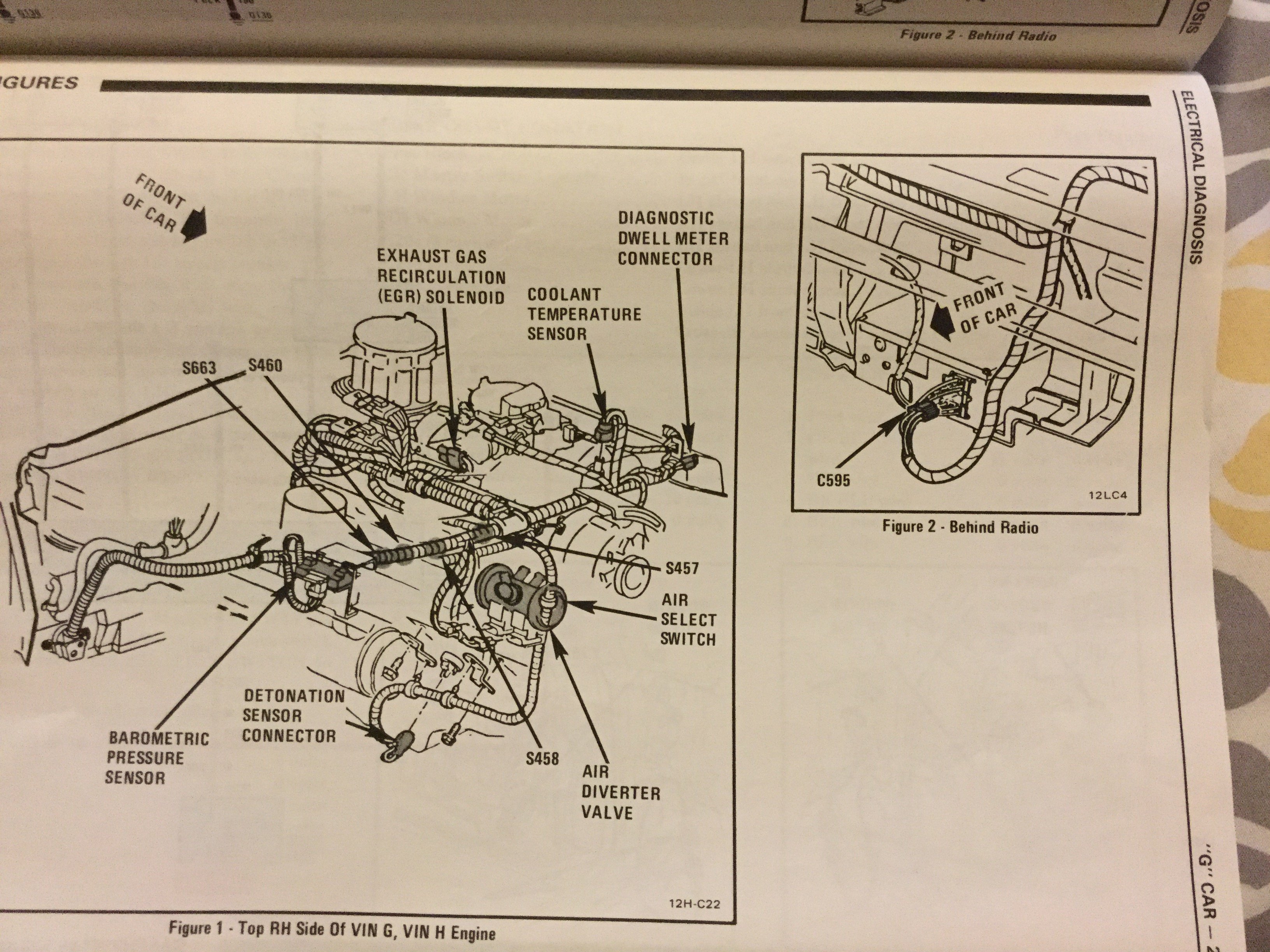
- Component Location: Determining the exact placement of electrical components, such as sensors, actuators, and modules.
- Connector Pinouts: Specifying the connections and functions of each pin within electrical connectors.
- Color-Coded Wiring: Understanding the color-coding system used for electrical wires, aiding in circuit tracing.
- Grounding Points: Identifying grounding locations for electrical circuits, essential for proper circuit operation.
- Power Distribution: Tracing the flow of electrical power from the battery to various components.
- Signal Pathways: Understanding the routes taken by electrical signals between components.
- Troubleshooting Guide: Providing a framework for diagnosing and resolving electrical faults.
These aspects are interconnected, forming a comprehensive blueprint of the vehicle’s electrical system. They empower technicians and enthusiasts to effectively maintain, repair, and modify G-Body vehicles, ensuring optimal performance and safety.
Circuit Identification
In the context of “G Body Wiring Diagram”, circuit identification plays a pivotal role in understanding the electrical system of G-Body vehicles. By identifying individual electrical circuits, technicians and enthusiasts can trace the flow of electricity, pinpoint faults, and perform repairs or modifications effectively.
- Component Identification: Circuit identification enables the recognition of individual electrical components, such as sensors, actuators, and modules, within the vehicle’s electrical system.
- Circuit Tracing: By tracing the paths of individual circuits, technicians can pinpoint the source of electrical faults and ensure proper signal transmission between components.
- Power Distribution Analysis: Circuit identification helps analyze the distribution of electrical power throughout the vehicle, ensuring that components receive the appropriate voltage and amperage.
- Grounding Verification: Identifying proper grounding points is crucial for ensuring the correct operation of electrical circuits and preventing electrical faults or malfunctions.
These facets of circuit identification are essential for the maintenance, repair, and modification of G-Body vehicles. They empower technicians and enthusiasts to work with the electrical system confidently, ensuring the optimal performance and safety of these vehicles.
Component Location
Within the context of “G Body Wiring Diagram,” component location plays a crucial role in understanding and troubleshooting the electrical system of G-Body vehicles. Identifying the precise placement of electrical components enables technicians and enthusiasts to:
- Physical Access: Locate components for inspection, maintenance, repair, or replacement, ensuring efficient and accurate work.
- Wiring Harness Routing: Determine the path of wiring harnesses to components, aiding in harness repair or modification.
- Signal Tracing: Trace electrical signals from sensors to actuators or modules, pinpointing faults and verifying proper signal transmission.
- Grounding Verification: Identify grounding points for electrical components, ensuring proper circuit operation and preventing electrical issues.
Understanding component location simplifies the process of diagnosing and resolving electrical problems in G-Body vehicles. It empowers technicians and enthusiasts to work with confidence, ensuring the optimal performance and safety of these vehicles.
Connector Pinouts
Within the context of “G Body Wiring Diagram”, connector pinouts play a pivotal role in understanding and troubleshooting the electrical system of G-Body vehicles. Identifying the connections and functions of each pin within electrical connectors enables technicians and enthusiasts to:
- Pin Identification: Recognize individual pins within electrical connectors, allowing for accurate wire connections and signal tracing.
- Signal Routing: Determine the pathways of electrical signals through connectors, ensuring proper signal transmission between components.
- Power Distribution Analysis: Analyze the distribution of electrical power through connectors, ensuring that components receive the appropriate voltage and amperage.
- Grounding Verification: Identify grounding points within connectors, ensuring proper circuit operation and preventing electrical faults or malfunctions.
Understanding connector pinouts simplifies the process of diagnosing and resolving electrical problems in G-Body vehicles. It empowers technicians and enthusiasts to work with confidence, ensuring the optimal performance and safety of these vehicles.
Color-Coded Wiring
Within the context of “G Body Wiring Diagram”, color-coded wiring plays a crucial role in simplifying circuit tracing and troubleshooting electrical systems. The color-coding system used for electrical wires provides a standardized method for identifying wire functions and tracing signal paths, enabling technicians and enthusiasts to work efficiently and accurately.
- Wire Identification: The color-coding system enables the quick identification of individual wires within a harness, reducing the time spent tracing and testing wires.
- Circuit Tracing: By following the color-coded wires, technicians can trace electrical circuits from one component to another, pinpointing faults and ensuring proper signal transmission.
- Power Distribution Analysis: The color-coding system helps identify power wires, ground wires, and signal wires, aiding in the analysis of power distribution throughout the vehicle’s electrical system.
- Grounding Verification: Color-coded wires are used to identify grounding points, ensuring proper circuit operation and preventing electrical faults or malfunctions.
The color-coded wiring system is a valuable tool for understanding and troubleshooting the electrical system of G-Body vehicles. It simplifies the process of circuit tracing, component identification, and fault diagnosis, empowering technicians and enthusiasts to maintain and repair these vehicles with confidence.
Grounding Points
Within the context of “G Body Wiring Diagram”, grounding points play a crucial role in ensuring the proper operation of electrical circuits. A grounding point provides a low-resistance path for electrical current to return to the vehicle’s electrical system, completing the circuit and allowing electrical components to function correctly. Identifying and understanding grounding points is essential for troubleshooting and repairing electrical faults in G-Body vehicles.
The “G Body Wiring Diagram” serves as a roadmap for the vehicle’s electrical system, detailing the connections between electrical components, sensors, and actuators. It also includes information on grounding points, indicating their locations and the circuits they serve. By referring to the wiring diagram, technicians can quickly identify and access grounding points for inspection, testing, or repair.
In practice, grounding points can become loose, corroded, or damaged over time, leading to electrical faults and malfunctions. Understanding the location of grounding points allows technicians to inspect and clean them as part of routine maintenance, preventing potential issues. Additionally, when troubleshooting electrical problems, identifying and verifying grounding points helps isolate the source of the fault, enabling efficient and accurate repairs.
In summary, grounding points are critical components of the electrical system in G-Body vehicles, and the “G Body Wiring Diagram” provides essential information for locating and understanding these points. By utilizing the wiring diagram and understanding the importance of grounding points, technicians and enthusiasts can effectively maintain, troubleshoot, and repair the electrical systems of these vehicles, ensuring their optimal performance and safety.
Power Distribution
In the context of “G Body Wiring Diagram”, understanding power distribution is crucial as it provides a roadmap for the flow of electrical power throughout the vehicle. The wiring diagram outlines the pathways of electrical current from the battery to various components, detailing the connections and voltage requirements of each component. This information is essential for troubleshooting electrical faults, ensuring proper circuit operation, and preventing electrical system malfunctions.
The “G Body Wiring Diagram” serves as a comprehensive guide to the electrical system, providing insights into the power distribution network. By tracing the flow of electrical power through the wiring diagram, technicians can identify potential power supply issues, voltage drops, and grounding problems. This enables them to diagnose and resolve electrical faults effectively, ensuring the optimal performance of G-Body vehicles.
In practice, power distribution analysis is critical for maintaining the electrical health of G-Body vehicles. Regular inspection and testing of power distribution circuits, such as battery terminals, wiring harnesses, and grounding points, help prevent electrical problems and ensure the reliable operation of vehicle systems. By understanding power distribution and utilizing the “G Body Wiring Diagram”, technicians can proactively identify and address potential power supply issues, minimizing downtime and enhancing vehicle safety.
Signal Pathways
In the context of “G Body Wiring Diagram”, understanding signal pathways is essential for troubleshooting and maintaining the electrical system. Signal pathways define the routes taken by electrical signals as they travel between various components within the vehicle.
-
Component Communication
Signal pathways allow different electrical components, such as sensors, actuators, and modules, to communicate with each other, enabling the exchange of information and control signals.
-
Signal Integrity
The integrity of signal pathways is crucial for ensuring that electrical signals are transmitted accurately and reliably. Factors such as wire quality, connector integrity, and proper grounding play vital roles in maintaining signal integrity.
-
Fault Diagnosis
Analyzing signal pathways is vital for diagnosing electrical faults. By tracing signal routes and measuring signal values, technicians can pinpoint the source of electrical problems and identify faulty components.
-
Circuit Modifications
Understanding signal pathways is essential when modifying electrical circuits. It allows technicians to identify appropriate points for tapping into existing circuits or adding new components while maintaining the integrity of the signal transmission.
In summary, understanding signal pathways is a fundamental aspect of “G Body Wiring Diagram”. It provides insights into the communication and control mechanisms within the vehicle’s electrical system, aiding in troubleshooting, maintenance, and modification tasks.
Troubleshooting Guide
In the context of “G Body Wiring Diagram”, the Troubleshooting Guide serves as an invaluable tool for diagnosing and resolving electrical faults effectively. It provides step-by-step guidance, error codes, and diagnostic procedures to help technicians pinpoint the source of electrical problems and implement appropriate repair strategies.
The Troubleshooting Guide is tightly integrated with the “G Body Wiring Diagram,” utilizing the wiring diagram as a reference for tracing circuits, identifying components, and understanding signal pathways. By combining the information from both resources, technicians can systematically troubleshoot electrical faults, saving time and ensuring accurate repairs.
For example, suppose a G-Body vehicle experiences an issue with the instrument cluster. The Troubleshooting Guide would provide a series of diagnostic steps, such as checking for loose connections, testing voltage levels, and examining signal continuity. Using the “G Body Wiring Diagram” alongside the Troubleshooting Guide, the technician can trace the relevant electrical circuits, identify the specific components involved, and perform the necessary tests to pinpoint the fault.
The practical applications of this understanding extend beyond troubleshooting. It also aids in preventive maintenance and system upgrades. By comprehending the electrical system through the Troubleshooting Guide and “G Body Wiring Diagram,” technicians can proactively identify potential issues, perform regular inspections, and make informed decisions about electrical modifications or upgrades.
In summary, the Troubleshooting Guide within the “G Body Wiring Diagram” provides a systematic approach to diagnosing and resolving electrical faults. Its integration with the wiring diagram empowers technicians to trace circuits, identify components, and perform effective repairs. This understanding is essential for maintaining the optimal performance and safety of G-Body vehicles.


Related Posts


