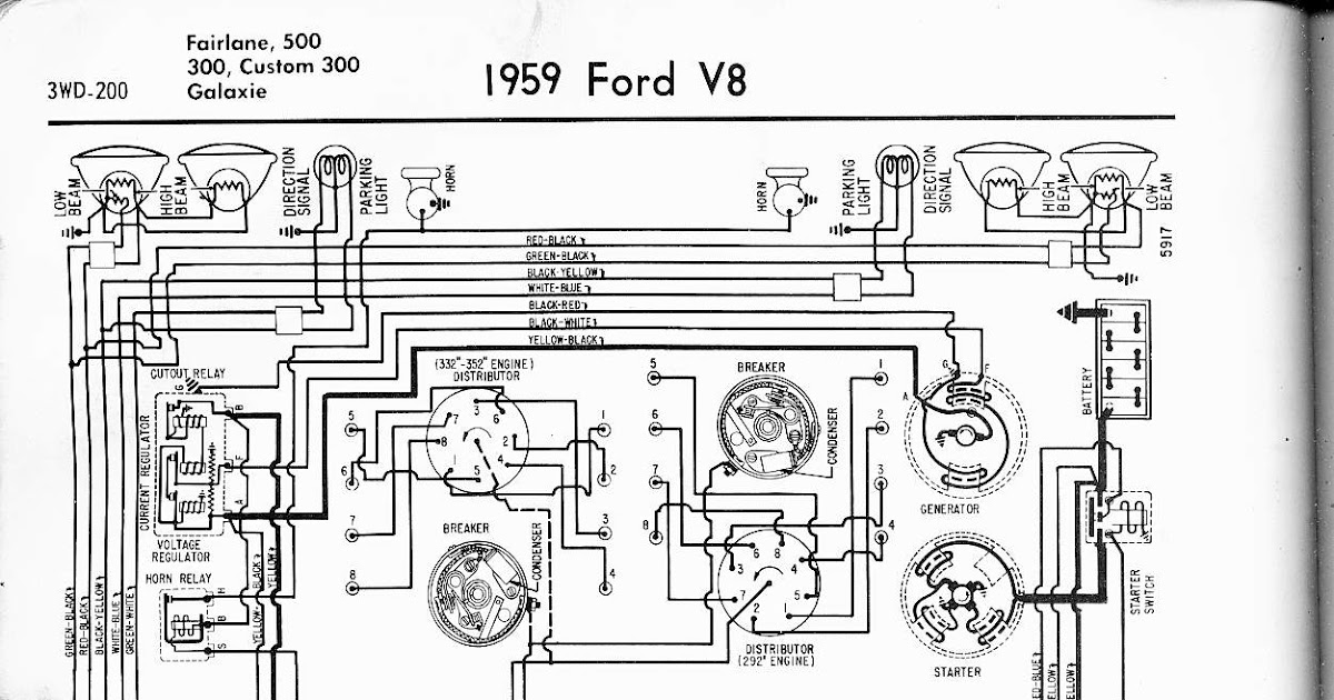
A Ford Steering Column Wiring Diagram outlines the electrical connections, wire colors, and component locations within the steering column of a Ford vehicle. It serves as a guide for troubleshooting electrical issues, repairing damaged wiring, and installing new components within the steering column assembly.
The diagram is crucial for ensuring proper electrical functioning of essential steering column components such as the ignition switch, turn signal lever, and cruise control module. It facilitates the identification and repair of electrical faults, improving the safety and reliability of the vehicle’s steering system.
A key historical development in Ford steering column wiring diagrams is the introduction of multi-function switches. These switches combine multiple functions, such as turn signals and wipers, onto a single stalk, simplifying the wiring and reducing the number of connections required.
Understanding the essential aspects of a Ford Steering Column Wiring Diagram is crucial for electrical troubleshooting, repair, and component installation within the steering column assembly. These aspects encompass various dimensions related to the diagram’s function, content, and historical context.
- Function: The diagram serves as a guide for troubleshooting electrical issues, repairing wiring, and installing components within the steering column, ensuring proper functioning of essential components.
- Content: It outlines the electrical connections, wire colors, and component locations within the steering column assembly.
- Accuracy: The diagram must be precise and up-to-date to ensure reliable electrical troubleshooting and repair.
- Clarity: The diagram should be easy to understand and interpret, even for individuals without extensive electrical knowledge.
- Comprehensiveness: It should cover all electrical connections and components within the steering column assembly.
- Availability: The diagram should be readily accessible to mechanics, technicians, and vehicle owners.
- Historical Context: The diagram reflects the evolution of steering column electrical systems in Ford vehicles, including the introduction of multi-function switches.
- Safety: Proper use of the diagram helps ensure the safety and reliability of the vehicle’s steering system.
- Troubleshooting: The diagram facilitates the identification and repair of electrical faults, reducing downtime and improving vehicle performance.
- Customization: The diagram can be customized to accommodate specific vehicle configurations and modifications.
In summary, these key aspects highlight the importance of a Ford Steering Column Wiring Diagram in maintaining the electrical integrity and functionality of the steering column assembly. It serves as a valuable tool for troubleshooting, repair, and customization, contributing to the overall safety and reliability of the vehicle.
Function
The function of a Ford Steering Column Wiring Diagram is directly tied to its purpose as a guide for troubleshooting electrical issues, repairing wiring, and installing components within the steering column. The diagram provides a visual representation of the electrical connections and component locations, enabling technicians and mechanics to diagnose and resolve electrical faults effectively. Without a clear and accurate diagram, troubleshooting and repair tasks would be significantly more challenging, leading to potential safety hazards and vehicle malfunctions.
Real-life examples of the function of a Ford Steering Column Wiring Diagram include:
- Identifying a faulty turn signal switch by tracing the electrical connections and checking for continuity.
- Repairing a damaged wire in the ignition switch circuit, ensuring proper starting of the vehicle.
- Installing a new cruise control module and connecting it to the steering column wiring harness.
Understanding the function of a Ford Steering Column Wiring Diagram is crucial for ensuring the proper functioning of essential steering column components. By providing a comprehensive overview of the electrical system, the diagram empowers technicians to perform accurate troubleshooting and repairs, contributing to the overall safety and reliability of the vehicle.
Content
The “Content” aspect of a Ford Steering Column Wiring Diagram refers to the detailed information it provides about the electrical system within the steering column assembly. This includes a comprehensive outline of the electrical connections, wire colors, and component locations.
- Electrical Connections: The diagram shows how the various electrical components within the steering column, such as the ignition switch, turn signal switch, and cruise control module, are interconnected. This information is crucial for troubleshooting electrical faults and ensuring proper functioning of the steering column.
- Wire Colors: The diagram specifies the color coding of the wires used in the steering column wiring harness. This helps in identifying and tracing specific wires, making it easier to diagnose and repair electrical issues.
- Component Locations: The diagram provides a visual representation of the physical location of each component within the steering column assembly. This information is essential for accessing and replacing components during repairs or modifications.
- Real-Life Example: To illustrate the practical significance of the “Content” aspect, consider a scenario where the turn signal switch malfunctions. By referring to the wiring diagram, a technician can identify the electrical connections, wire colors, and component location related to the turn signal switch. This information enables the technician to quickly diagnose the fault and perform the necessary repairs.
In summary, the “Content” aspect of a Ford Steering Column Wiring Diagram provides a comprehensive overview of the electrical system within the steering column assembly. It outlines the electrical connections, wire colors, and component locations, enabling technicians and mechanics to effectively troubleshoot, repair, and modify the steering column electrical system, ensuring the safety and reliability of the vehicle.
Accuracy
Accuracy is a critical component of a Ford Steering Column Wiring Diagram. Precise and up-to-date diagrams are essential for effective electrical troubleshooting and repair, as they provide technicians with the correct information to diagnose and resolve electrical faults. Inaccurate or outdated diagrams can lead to misdiagnosis, incorrect repairs, and potential safety hazards.
A real-life example of the importance of accuracy in a Ford Steering Column Wiring Diagram is a scenario where a technician is troubleshooting a faulty turn signal switch. An inaccurate diagram could provide incorrect wire colors or component locations, misleading the technician and potentially leading to an incorrect repair. An up-to-date diagram, on the other hand, ensures that the technician has the most current information, increasing the likelihood of a successful repair.
The practical significance of understanding the connection between accuracy and Ford Steering Column Wiring Diagrams lies in the ability to perform reliable electrical troubleshooting and repairs. Accurate diagrams empower technicians to:
- Correctly identify faulty components
- Trace and repair electrical faults
- Install new components with confidence
- Ensure the proper functioning of the steering column electrical system
In summary, the accuracy of Ford Steering Column Wiring Diagrams is paramount for reliable electrical troubleshooting and repair. Precise and up-to-date diagrams provide technicians with the correct information to diagnose and resolve electrical faults effectively, ensuring the safety and reliability of the vehicle.
Clarity
In the context of Ford Steering Column Wiring Diagrams, clarity is of utmost importance to ensure effective troubleshooting, repair, and modification of the steering column electrical system. The diagram should be designed with simplicity and ease of comprehension in mind, allowing individuals with varying levels of electrical knowledge to use it effectively.
A clear and understandable diagram empowers technicians, mechanics, and even vehicle owners to:
- Quickly identify electrical faults
- Diagnose and resolve issues efficiently
- Perform repairs with confidence
- Modify or customize the steering column electrical system as needed
Real-life examples of clarity in Ford Steering Column Wiring Diagrams include:
- Using color-coded wires and clear labeling to simplify wire identification
- Providing detailed annotations and descriptions to explain the function of each component
- Organizing the diagram in a logical and intuitive manner
Understanding the connection between clarity and Ford Steering Column Wiring Diagrams is essential for several reasons:
- Reduced troubleshooting time: Clear diagrams enable technicians to identify and resolve electrical faults more quickly and efficiently.
- Increased accuracy of repairs: Clarity minimizes the risk of misdiagnosis and incorrect repairs, ensuring the proper functioning of the steering column electrical system.
- Improved safety: Accurate and understandable diagrams contribute to the overall safety of the vehicle by reducing the likelihood of electrical malfunctions.
- Simplified modifications: Clear diagrams facilitate the modification or customization of the steering column electrical system, allowing for upgrades or personalized configurations.
In summary, clarity is a critical component of Ford Steering Column Wiring Diagrams, enabling effective troubleshooting, repair, and modification of the steering column electrical system. Clear and understandable diagrams empower individuals with varying levels of electrical knowledge to maintain and customize their vehicles safely and efficiently.
Comprehensiveness
Comprehensiveness is a critical component of Ford Steering Column Wiring Diagrams, ensuring they provide a complete and accurate representation of the steering column electrical system. Diagrams that cover all electrical connections and components empower technicians and individuals to effectively troubleshoot, repair, and modify the steering column electrical system with confidence.
A real-life example of the importance of comprehensiveness in Ford Steering Column Wiring Diagrams is a scenario where a technician encounters an intermittent electrical fault in the steering column. A comprehensive diagram enables the technician to trace all electrical connections and identify all components within the steering column assembly. This thorough approach increases the likelihood of identifying the root cause of the fault and performing a successful repair.
The practical significance of understanding the connection between comprehensiveness and Ford Steering Column Wiring Diagrams lies in the ability to:
- Identify and resolve electrical faults accurately and efficiently
- Ensure the proper functioning of all steering column components
- Perform modifications or upgrades to the steering column electrical system with confidence
In summary, comprehensiveness is a key aspect of Ford Steering Column Wiring Diagrams, enabling effective troubleshooting, repair, and modification of the steering column electrical system. Comprehensive diagrams provide a complete and accurate representation of all electrical connections and components, empowering individuals to maintain and customize their vehicles safely and reliably.
Availability
Within the context of Ford Steering Column Wiring Diagrams, “Availability” plays a pivotal role in ensuring the effective utilization of these diagrams for troubleshooting, repair, and modification of the steering column electrical system. When the diagram is readily accessible to mechanics, technicians, and even vehicle owners, it empowers them to maintain and customize their vehicles safely and efficiently.
- Online Accessibility: Ford Steering Column Wiring Diagrams are often available online through the manufacturer’s website, automotive forums, and online databases. This accessibility allows individuals to access the diagrams from any location with an internet connection, facilitating remote troubleshooting and repairs.
- Service Manuals: Ford Steering Column Wiring Diagrams are typically included in the vehicle’s service manual. These manuals are readily available for purchase from dealerships or online retailers, providing a comprehensive reference for vehicle maintenance and repairs.
- Vehicle Documentation: Some Ford vehicles come with the steering column wiring diagram included in the owner’s manual or glovebox documentation. This provides convenient access to the diagram, especially during roadside repairs or troubleshooting situations.
- Third-Party Sources: Ford Steering Column Wiring Diagrams may also be available through third-party publishers and automotive repair information providers. These sources offer diagrams for a wide range of Ford vehicles and model years, catering to a broader audience.
The availability of Ford Steering Column Wiring Diagrams has several practical implications. Firstly, it reduces downtime for vehicle repairs by providing instant access to the necessary information. Secondly, it empowers individuals to perform basic electrical troubleshooting and repairs, saving on labor costs and increasing self-reliance. Thirdly, it facilitates modifications and upgrades to the steering column electrical system, allowing for personalized configurations and enhanced functionality.
In summary, the availability of Ford Steering Column Wiring Diagrams to mechanics, technicians, and vehicle owners is crucial for efficient troubleshooting, repair, modification, and maintenance of the steering column electrical system. By providing convenient access to these diagrams through various sources, Ford ensures that individuals have the necessary information to keep their vehicles operating safely and reliably.
Historical Context
The historical context of Ford Steering Column Wiring Diagrams is closely intertwined with the evolution of steering column electrical systems in Ford vehicles. As technology advanced and the demand for more functionality increased, the electrical systems within the steering column underwent significant changes.
One of the most notable developments was the introduction of multi-function switches. These switches combine multiple functions, such as turn signals, wipers, and cruise control, onto a single stalk. This integration reduced the number of separate switches and simplified the wiring, making the steering column more compact and user-friendly.
The Ford Steering Column Wiring Diagram reflects these historical developments by providing detailed information on the electrical connections, wire colors, and component locations for each model year and vehicle configuration. By understanding the historical context, technicians and enthusiasts can gain valuable insights into the design and functionality of the steering column electrical system.
For example, a technician troubleshooting a faulty turn signal switch on a classic Ford Mustang can refer to the wiring diagram to identify the specific wire colors and connections associated with the turn signal circuit. Similarly, an enthusiast looking to install a custom steering wheel with integrated audio controls can use the diagram to determine the necessary wiring modifications.
In summary, the historical context of Ford Steering Column Wiring Diagrams is crucial for understanding the evolution of steering column electrical systems and for performing accurate troubleshooting, repairs, and modifications. By providing a comprehensive overview of the electrical system’s development, the diagram empowers individuals to maintain and customize their vehicles safely and efficiently.
Safety
Within the context of Ford Steering Column Wiring Diagrams, “Safety” plays a pivotal role in ensuring the proper functioning of the vehicle’s steering system. These diagrams provide crucial information for troubleshooting, repair, and modification of the electrical system within the steering column, which directly impacts the safety and reliability of the vehicle.
- Accurate Wiring: Proper use of the diagram ensures accurate wiring connections, eliminating potential electrical faults that could lead to system malfunctions or even accidents.
- Component Compatibility: The diagram specifies the correct electrical components and their compatibility with the steering column assembly. Using incorrect components can compromise the integrity of the electrical system and affect steering performance.
- Circuit Protection: Wiring diagrams indicate the location and specifications of fuses and circuit breakers within the steering column. Proper use of the diagram ensures that these protective devices are correctly installed and functioning, preventing electrical overloads and potential fires.
- Grounding: The diagram provides information on proper grounding points for the steering column electrical system. Correct grounding ensures that electrical current flows safely and prevents interference with other electronic systems in the vehicle.
Understanding and adhering to the safety guidelines outlined in Ford Steering Column Wiring Diagrams is paramount. Accurate wiring, compatible components, proper circuit protection, and correct grounding work together to ensure the safety and reliability of the vehicle’s steering system. By following these guidelines, technicians and individuals can maintain and modify their vehicles with confidence, knowing that the steering column electrical system is functioning optimally.
Troubleshooting
Within the context of Ford Steering Column Wiring Diagrams, “Troubleshooting” plays a central role in maintaining the safety and reliability of the vehicle’s steering system. These diagrams provide essential information for identifying and repairing electrical faults within the steering column, directly contributing to the overall performance and functionality of the vehicle.
Ford Steering Column Wiring Diagrams serve as comprehensive guides for troubleshooting electrical issues, allowing technicians and individuals to quickly and accurately diagnose and resolve problems. By providing detailed information on electrical connections, wire colors, and component locations, the diagrams empower users to trace and identify faulty components, perform repairs, and restore the steering column electrical system to optimal working condition.
Real-life examples of troubleshooting using Ford Steering Column Wiring Diagrams include:
- Identifying a blown fuse or faulty wire causing intermittent turn signal operation
- Diagnosing a malfunctioning cruise control system by tracing electrical connections
- Resolving an issue with the horn or airbag system by locating and repairing damaged wiring
The practical significance of understanding the connection between troubleshooting and Ford Steering Column Wiring Diagrams lies in the ability to effectively maintain and repair the vehicle’s steering system. Accurate troubleshooting minimizes downtime, improves vehicle performance, and ensures the safety and reliability of the steering system. By utilizing these diagrams, individuals can confidently troubleshoot and resolve electrical faults, reducing the need for costly repairs or professional assistance.
In summary, the ability to troubleshoot electrical faults using Ford Steering Column Wiring Diagrams is a critical component of maintaining vehicle safety and performance. These diagrams empower users to identify and repair electrical issues, reducing downtime and improving vehicle functionality. Understanding this connection is essential for ensuring the reliability and longevity of the vehicle’s steering system.
Customization
Within the realm of Ford Steering Column Wiring Diagrams, “Customization” plays a significant role in adapting the diagram to specific vehicle requirements and modifications. The ability to customize the diagram empowers individuals to tailor the electrical system to their unique needs, enhancing functionality and optimizing performance.
- Component Selection: The diagram allows for the customization of electrical components based on vehicle configuration. This includes selecting compatible switches, sensors, and actuators to match the specific features and options installed on the vehicle.
- Wiring Modifications: The diagram serves as a guide for modifying the wiring harness to accommodate changes in component placement or the addition of new electrical accessories. By following the diagram, individuals can ensure proper wire routing and connections, maintaining electrical integrity.
- Real-Life Example: Upgrading the audio system in a Ford F-150 requires modifications to the steering column wiring to integrate the new head unit and speakers. The wiring diagram provides the necessary information to identify the correct wires and make the appropriate connections.
- Implications: Customization of the Ford Steering Column Wiring Diagram enables personalized configurations, improved functionality, and the seamless integration of aftermarket components, ultimately enhancing the driving experience.
In summary, the “Customization” aspect of Ford Steering Column Wiring Diagrams empowers individuals to adapt the electrical system to their specific vehicle configurations and modifications. By providing a detailed representation of the electrical connections, wire colors, and component locations, the diagram serves as a valuable tool for customizing the steering column electrical system, ensuring optimal performance and functionality.


![[DIAGRAM] 1954 Ford Steering Column Wiring Diagrams](https://lh5.googleusercontent.com/proxy/OADr81q-aa7iEqb299Ntpks2ELcXoIuh8IUxdPN7KI9RrjXgIqHTN7cPGCuqaTK46gGEX3ruMtTIQKNlxnQ4x1ZN37CRZAkaWG1RpW6VGgEFnuUu1AMPKTUnhI_uanv7Vx52PyNRaQ6TUcia9wrM3A94Y83QhmecQLqkB1kNJwjKPUiMP90QiFhv3CC0uWVI_YEQlHB_7qrlPz3IH-rhBqCTlvit5zrZA3E7lPDR0dQSRikCKTg=s0-d)

![[DIAGRAM] 1966 Ford F100 Steering Column Wiring Diagram](https://i0.wp.com/img402.imageshack.us/img402/2078/shiftlinkage001.jpg?w=665&ssl=1)

Related Posts


