A Float Switch Wiring Diagram is a schematic representation of the electrical connections and components in a float switch system. It provides a visual guide for understanding and installing the system correctly.
The core function of a float switch wiring diagram is to enable proper operation and safety of the float switch system. By indicating the connections between the float switch, power source, and any other electrical devices, the diagram ensures that the system functions as intended and avoids electrical hazards.
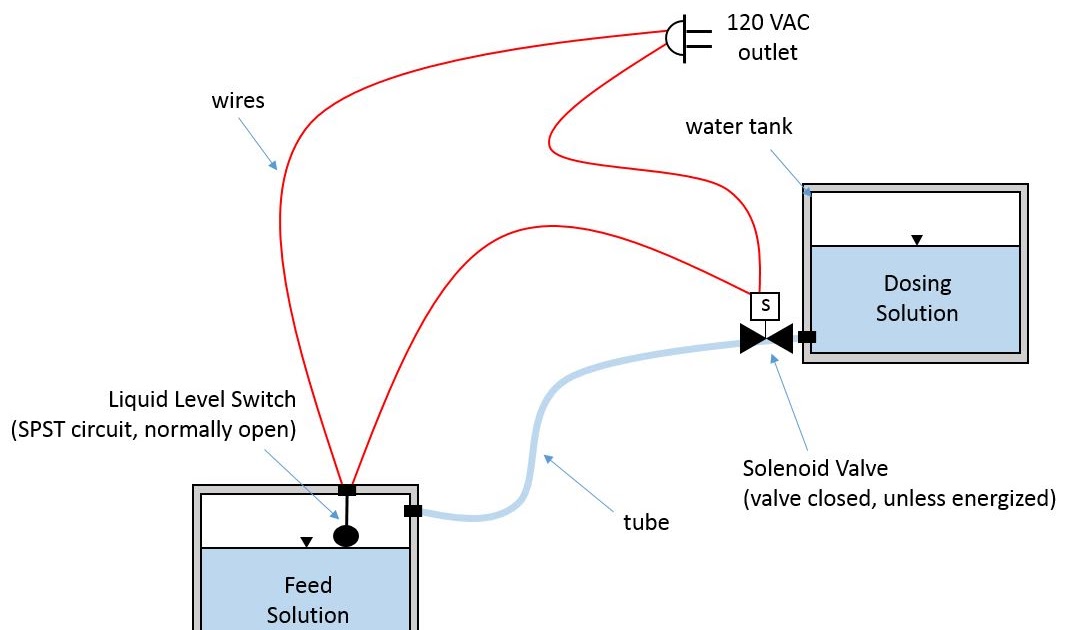
A typical example of a float switch wiring diagram is in a sump pump or tank application. Here, the diagram shows how the float switch connects to the pump, power source, and any additional control components. This information is crucial for proper installation and ensures that the pump will activate and drain excess water when the liquid level reaches a specific point.
Float switch wiring diagrams are highly relevant for maintaining the safety and functionality of various liquid level monitoring systems. They simplify the installation process, minimize the risk of electrical errors, and provide a valuable reference for troubleshooting and maintenance.
A key historical development in float switch wiring diagrams was the standardization of symbols and conventions. This made diagrams easier to understand and interpret, ensuring consistency across different manufacturers and systems.
As we delve into this technical article, we will explore the key elements of a float switch wiring diagram, best practices for installation and maintenance, and practical tips for troubleshooting common issues.
Float Switch Wiring Diagrams are integral to the safe and efficient operation of float switch systems. Understanding their essential aspects is crucial for proper installation, maintenance, and troubleshooting.
- Components: Identifying the components in the diagram, such as the float switch, power source, and any other electrical devices.
- Connections: Understanding how the components are connected, including wire types, terminals, and polarity.
- Safety Features: Noting any safety features incorporated into the diagram, such as grounding and circuit protection.
- Control Logic: Analyzing the control logic implemented in the diagram, such as pump activation levels and time delays.
- Power Requirements: Determining the power requirements of the system, including voltage, current, and power factor.
- Wire Sizing: Calculating the appropriate wire size based on the current carrying capacity and voltage drop considerations.
- Conduit and Fittings: Specifying the type and size of conduit and fittings used to protect and route the wiring.
- Environmental Considerations: Taking into account environmental factors such as temperature, humidity, and exposure to chemicals or moisture.
These key aspects provide a comprehensive understanding of Float Switch Wiring Diagrams. They ensure the proper operation of the system, minimize electrical hazards, and facilitate efficient maintenance and troubleshooting. By considering these aspects, engineers and technicians can design, install, and maintain float switch systems that meet specific application requirements and safety standards.
Components: Identifying the components in the diagram, such as the float switch, power source, and any other electrical devices.
In the context of Float Switch Wiring Diagrams, identifying the components and their interconnections is paramount for understanding system functionality and ensuring proper installation and maintenance. Various components play crucial roles in the operation of a float switch system, each with its specific purpose and characteristics.
- Float Switch: The heart of the system, the float switch monitors liquid levels and triggers actions based on pre-defined setpoints. It consists of a float that moves with the liquid level, actuating internal mechanisms to open or close electrical contacts.
- Power Source: Typically mains electricity or a battery, the power source provides the electrical energy required to operate the float switch and connected devices. Its voltage and current ratings must match the system requirements.
- Control Panel: In complex systems, a control panel houses additional electrical components such as relays, timers, and programmable logic controllers. It provides centralized control and monitoring capabilities.
- Pumps and Valves: Float switches are often used to control pumps or valves that manage liquid flow. These devices are connected to the float switch’s electrical output, allowing them to be automatically activated or deactivated based on liquid level changes.
Understanding the function and proper wiring of these components is essential for the safe and effective operation of Float Switch Wiring Diagrams. Correct identification and connection ensure that the system responds appropriately to liquid level changes, triggering desired actions and preventing potential hazards.
Connections: Understanding how the components are connected, including wire types, terminals, and polarity.
In the context of Float Switch Wiring Diagrams, understanding the connections between components is paramount for ensuring proper system operation and safety. These connections involve the selection of appropriate wire types, terminals, and consideration of polarity, all of which play critical roles in the effective functioning of the system.
Wire Types: The type of wire used in a Float Switch Wiring Diagram is crucial for ensuring proper current carrying capacity and minimizing voltage drop. Factors such as wire gauge, insulation material, and flexibility must be considered based on the specific requirements of the system. Correct wire selection prevents overheating, voltage loss, and potential electrical hazards.
Terminals: Terminals provide secure and reliable connections between wires and components. Proper selection of terminals ensures a good electrical connection, preventing loose connections, arcing, and potential equipment damage. Factors to consider include terminal size, type (e.g., screw terminals, crimp terminals), and material compatibility.
Polarity: In certain applications, such as when connecting a float switch to a DC power source, polarity must be observed. Incorrect polarity can damage components or prevent the system from functioning properly. Float Switch Wiring Diagrams clearly indicate the polarity of connections, ensuring that positive and negative terminals are connected accordingly.
Real-life examples of the importance of connections in Float Switch Wiring Diagrams abound. In industrial settings, improper connections can lead to equipment failures, production downtime, and safety hazards. In residential applications, faulty connections can cause electrical fires or damage to appliances.
Understanding the principles of connections in Float Switch Wiring Diagrams is essential for safe and effective system operation. By selecting the appropriate wire types, terminals, and observing polarity, engineers and technicians can ensure that float switch systems function as intended, providing reliable liquid level monitoring and control.
Safety Features: Noting any safety features incorporated into the diagram, such as grounding and circuit protection.
In the context of Float Switch Wiring Diagrams, safety features play a critical role in ensuring the protection of personnel and equipment. These features are incorporated into the diagram to minimize electrical hazards, prevent damage, and maintain system integrity.
Grounding is a fundamental safety feature that provides a low-resistance path for electrical current to flow to the ground. In Float Switch Wiring Diagrams, grounding is typically achieved by connecting the system’s electrical components to a grounding electrode, such as a metal rod driven into the earth. This ensures that any fault currents are safely dissipated into the ground, preventing dangerous voltage buildup on the system.
Circuit protection devices, such as fuses and circuit breakers, are another essential safety feature. These devices are designed to interrupt the flow of electrical current in the event of an overload or short circuit. By doing so, they protect electrical components from damage and prevent electrical fires.
Real-life examples of the importance of safety features in Float Switch Wiring Diagrams are numerous. In industrial settings, grounding and circuit protection have prevented serious electrical accidents, protecting both workers and equipment. In residential applications, these safety features have prevented electrical fires and damage to appliances, ensuring the safety of occupants.
Understanding the principles of safety features in Float Switch Wiring Diagrams is essential for ensuring safe and reliable system operation. By incorporating these features into their designs, engineers and technicians can minimize electrical hazards and create systems that meet industry standards and regulations.
Control Logic: Analyzing the control logic implemented in the diagram, such as pump activation levels and time delays.
Control logic is a fundamental aspect of Float Switch Wiring Diagrams, determining how the system responds to changes in liquid level and initiates appropriate actions. Analyzing the control logic is crucial for understanding system functionality and ensuring proper operation.
- Pump Activation Levels: Float switches can be configured with specific activation levels, determining the liquid level at which the connected pump turns on and off. These levels are set based on application requirements and considerations such as tank capacity and desired liquid level range.
- Time Delays: Time delays are often incorporated into the control logic to prevent rapid cycling of the pump or valve. This is achieved by introducing a delay between the activation of the float switch and the operation of the connected device. Time delays help minimize wear and tear on equipment and prevent system instability.
- Interlocks: Interlocks are used to prevent conflicting operations within the system. For example, in a sump pump application, an interlock can be implemented to prevent the pump from operating if the discharge line is blocked.
- Alarm and Notification: Control logic can include provisions for alarm and notification systems. These features alert operators to abnormal conditions, such as high or low liquid levels, or system malfunctions.
Understanding the principles of control logic in Float Switch Wiring Diagrams is essential for designing and maintaining effective liquid level monitoring and control systems. By carefully analyzing and implementing control logic, engineers and technicians can ensure that the system operates safely, reliably, and efficiently.
Power Requirements: Determining the power requirements of the system, including voltage, current, and power factor.
In the context of Float Switch Wiring Diagrams, understanding the power requirements of the system is essential for ensuring compatibility and safe operation. The power requirements, including voltage, current, and power factor, determine the electrical characteristics of the system and influence the selection of components and wiring.
The voltage and current requirements of the float switch and any connected devices must match the power source’s capabilities. Incorrect voltage or current can damage components or lead to system malfunctions. Power factor, which represents the phase difference between voltage and current, also affects the system’s efficiency and power consumption.
Real-life examples highlight the importance of considering power requirements in Float Switch Wiring Diagrams. In industrial settings, mismatched power requirements can lead to equipment failures and downtime. In residential applications, incorrect power supply can damage appliances or pose safety hazards.
Understanding the principles of power requirements in Float Switch Wiring Diagrams enables engineers and technicians to design and maintain systems that operate safely and efficiently. By carefully considering the power requirements and selecting appropriate components, they can ensure that the system meets the intended application’s needs.
Wire Sizing: Calculating the appropriate wire size based on the current carrying capacity and voltage drop considerations.
In the context of Float Switch Wiring Diagrams, wire sizing plays a critical role in ensuring the safe and efficient operation of the system. The appropriate wire size must be carefully calculated based on the current carrying capacity and voltage drop considerations to avoid potential hazards and ensure system reliability.
Current carrying capacity refers to the maximum amount of current that a wire can safely carry without overheating or causing insulation damage. Exceeding the current carrying capacity can lead to fires or equipment malfunctions. Voltage drop, on the other hand, is the reduction in voltage that occurs over the length of a wire due to its resistance. Excessive voltage drop can result in reduced system performance or even equipment damage.
Real-life examples underscore the importance of proper wire sizing in Float Switch Wiring Diagrams. In industrial settings, undersized wires can lead to equipment failures and production downtime. In residential applications, incorrect wire sizing can pose safety hazards or damage appliances.
Understanding the principles of wire sizing enables engineers and technicians to design and maintain Float Switch Wiring Diagrams that meet the specific requirements of the application. By selecting the appropriate wire size based on the current carrying capacity and voltage drop considerations, they can ensure that the system operates safely, reliably, and efficiently.
Conduit and Fittings: Specifying the type and size of conduit and fittings used to protect and route the wiring.
Within the context of Float Switch Wiring Diagrams, the selection of appropriate conduit and fittings is crucial for ensuring the protection, routing, and organization of electrical wiring. Conduit, a protective casing, and fittings, such as connectors and bends, provide mechanical protection and maintain the integrity of the electrical system.
- Conduit Type: The type of conduit used depends on the application environment and requirements. Common types include PVC (polyvinyl chloride) for general-purpose installations, metal conduit for added protection in harsh environments, and flexible conduit for ease of installation in tight spaces.
- Conduit Size: The size of the conduit is determined by the number and size of wires it needs to accommodate. Overcrowding wires in a conduit can lead to overheating and insulation damage. Proper sizing ensures adequate space for wire movement and heat dissipation.
- Fittings: Fittings play a vital role in connecting, changing direction, and terminating conduit runs. Common fittings include elbows, couplings, and junction boxes. Selecting the appropriate fittings ensures a secure and organized wiring system.
- Environmental Considerations: The choice of conduit and fittings should take into account environmental factors such as temperature, moisture, and chemical exposure. Selecting materials that can withstand the specific conditions ensures the longevity and safety of the wiring system.
Properly specifying the type and size of conduit and fittings in Float Switch Wiring Diagrams is essential for ensuring a safe, reliable, and efficient electrical system. By considering the factors discussed above, engineers and technicians can design and implement wiring systems that meet the specific requirements of the application.
Environmental Considerations: Taking into account environmental factors such as temperature, humidity, and exposure to chemicals or moisture.
Within the context of Float Switch Wiring Diagrams, environmental considerations play a crucial role in ensuring the reliability, safety, and longevity of the electrical system. Float switches operate in diverse environments, each posing unique challenges that must be addressed during the design and installation phases.
Temperature fluctuations can significantly impact the performance and lifespan of electrical components. Extreme temperatures can cause insulation breakdown, contact corrosion, and premature failure of wires and terminals. Selecting materials and components with appropriate temperature ratings is essential to ensure uninterrupted operation in varying temperature conditions.
Humidity and moisture exposure can lead to insulation degradation, short circuits, and even electrocution hazards. In humid environments, moisture can condense on electrical components, providing a conductive path for current leakage or arcing. Proper sealing, ventilation, and the use of moisture-resistant materials are crucial to prevent these issues.
Exposure to chemicals or corrosive substances can damage wiring insulation and metallic components. Chemical resistance is particularly important in industrial settings or areas where harsh cleaning agents or chemicals are present. Selecting materials compatible with the anticipated chemical environment ensures the integrity and safety of the wiring system.
Real-life examples underscore the importance of environmental considerations in Float Switch Wiring Diagrams. In outdoor applications, temperature variations and moisture exposure can lead to premature failure of wiring and components if not adequately protected. In industrial environments, chemical exposure can cause insulation breakdown and short circuits, posing safety hazards.
Understanding the impact of environmental factors on Float Switch Wiring Diagrams enables engineers and technicians to design and implement robust electrical systems that can withstand the rigors of their operating environment. By carefully considering temperature, humidity, and chemical exposure, they can select appropriate materials, components, and installation practices to ensure the safety, reliability, and longevity of the system.


Related Posts


