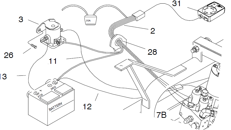
A Fisher plow solenoid wiring diagram is a schematic representation of the electrical connections for a Fisher snowplow’s solenoid, which is an electromagnetic device that controls the plow’s movement. For instance, a wiring diagram might show the connections between the solenoid, battery, plow motor, and control switch.
These diagrams are crucial for troubleshooting and repairing snowplows, ensuring they function correctly during winter operations. They provide a clear understanding of the electrical system, enabling technicians to identify and fix issues efficiently. A significant historical development in this field was the introduction of color-coded wiring to simplify the identification of different electrical connections, reducing the time and effort required for troubleshooting.
This article will delve into the intricacies of Fisher plow solenoid wiring diagrams, exploring their components, wiring configurations, and practical applications in greater detail.
As a noun phrase, “Fisher Plow Solenoid Wiring Diagram” represents the blueprint for the electrical connections within a Fisher snowplow’s solenoid system. Understanding its key aspects is crucial for proper installation, maintenance, and troubleshooting.
- Components: Solenoid, battery, plow motor, control switch
- Connections: Wires, terminals, connectors
- Voltage: Typically 12 or 24 volts DC
- Current: Varies depending on plow size and type
- Wiring Configuration: Parallel or series circuits
- Color Coding: Simplifies identification
- Troubleshooting: Diagrams aid in fault finding
- Safety: Proper wiring ensures safe operation
These aspects are interconnected. For instance, the voltage and current determine the wire gauge required for safe operation. Color coding simplifies troubleshooting by allowing technicians to trace connections quickly. Understanding these aspects collectively empowers technicians to maintain and repair Fisher snowplows effectively.
Components
Understanding the components of a Fisher plow solenoid wiring diagram is critical for proper installation, maintenance, and troubleshooting. These components include the solenoid, battery, plow motor, and control switch, each playing a distinct role in the system’s operation.
-
Solenoid:
An electromagnetic device that controls the flow of electricity to the plow motor. When activated, it engages the plow’s gears, raising or lowering the plow blade.
-
Battery:
Provides the electrical power to operate the solenoid and plow motor. Typically a 12 or 24-volt DC battery is used.
-
Plow Motor:
A heavy-duty electric motor that drives the plow’s hydraulic pump, which in turn raises or lowers the plow blade.
-
Control Switch:
A switch mounted in the vehicle’s cab that allows the operator to activate the solenoid and raise or lower the plow blade.
These components work together to form a complete electrical circuit. When the operator activates the control switch, electricity flows from the battery to the solenoid, engaging the plow motor and raising or lowering the plow blade. Proper wiring and maintenance of these components ensure reliable operation of the Fisher snowplow.
Connections
In the context of a Fisher plow solenoid wiring diagram, connections refer to the wires, terminals, and connectors that establish the electrical pathways between the solenoid, battery, plow motor, and control switch. These connections play a critical role in the proper functioning of the snowplow’s electrical system.
Wires serve as the conduits for electrical current to flow between the different components. Terminals provide secure and reliable connections between wires and components, ensuring a complete circuit. Connectors allow for easy assembly and disassembly of the electrical system, facilitating maintenance and repairs. Without these connections, the solenoid would not be able to activate the plow motor, and the plow blade would remain inoperable.
A real-life example of connections in a Fisher plow solenoid wiring diagram is the use of color-coded wires. Each wire is assigned a specific color to indicate its function (e.g., red for power, black for ground). This color-coding simplifies the identification of wires during installation, troubleshooting, and repairs, reducing the risk of errors and ensuring the proper operation of the snowplow.
Understanding the connections in a Fisher plow solenoid wiring diagram is essential for technicians and plow operators alike. It enables them to diagnose and fix electrical issues quickly and efficiently, minimizing downtime and ensuring the proper functioning of the snowplow during critical winter operations.
Voltage
In the context of Fisher plow solenoid wiring diagrams, the voltage used is typically either 12 or 24 volts DC (direct current). This voltage level is crucial for ensuring the proper operation and efficiency of the snowplow’s electrical system.
- Battery Compatibility: The voltage of the solenoid must match the voltage of the battery used to power the system. Most vehicles use either 12-volt or 24-volt batteries, so the solenoid must be selected accordingly.
- Solenoid Activation: The voltage supplied to the solenoid determines its ability to activate and engage the plow motor. The correct voltage ensures that the solenoid receives sufficient power to generate the necessary magnetic field for activation.
- Plow Motor Operation: The voltage supplied to the plow motor affects its speed and torque output. Higher voltage typically results in increased motor power, enabling the plow to lift and lower the plow blade more efficiently.
- Safety Considerations: Using the correct voltage is essential for safety. Higher voltage can damage components and pose electrical hazards, while lower voltage may not provide enough power for reliable operation.
Understanding the voltage requirements of a Fisher plow solenoid wiring diagram is crucial for selecting the appropriate components and ensuring the safe and effective operation of the snowplow. Adhering to the specified voltage levels guarantees that the solenoid and other electrical components function optimally, maximizing the performance and reliability of the snowplow.
Current
Within the context of Fisher plow solenoid wiring diagrams, the current requirement varies significantly based on the size and type of the plow being used. Understanding the factors that influence current draw is crucial for selecting appropriate components and ensuring the proper functioning of the snowplow’s electrical system.
-
Plow Size:
Larger plows, such as those designed for heavy-duty commercial use, require higher current to operate efficiently. This is because larger plows have more powerful motors that draw more current to lift and lower the plow blade.
-
Plow Type:
Different types of plows, such as V-plows and straight blades, have varying current requirements. V-plows typically require higher current due to the increased friction and resistance encountered when pushing snow to the sides.
-
Motor Specifications:
The current draw of a snowplow is also influenced by the specifications of the electric motor used. Motors with higher power ratings and torque capabilities require higher current to operate.
-
Electrical System Capacity:
The vehicle’s electrical system must be capable of supplying the required current for the snowplow. Insufficient current supply can lead to overheating, voltage drops, and potential damage to the electrical components.
Comprehending the relationship between current and plow size and type enables technicians and installers to accurately size electrical components, select appropriate wiring gauges, and ensure the snowplow operates at its optimal efficiency. Ignoring these factors can result in inadequate performance, premature component failure, or even electrical hazards.
Wiring Configuration
Within the context of Fisher plow solenoid wiring diagrams, the wiring configuration plays a critical role in determining the electrical characteristics and functionality of the system. Two primary wiring configurations are commonly used: parallel and series circuits.
Parallel Circuits: In a parallel circuit, the solenoid and other electrical components are connected in such a way that they receive the same voltage. This configuration allows each component to operate independently, and the overall current draw is divided among the components. Parallel circuits are often used when multiple solenoids or other devices need to be powered simultaneously.
Series Circuits: In a series circuit, the solenoid and other electrical components are connected in a single loop, with the current flowing through each component in sequence. This configuration results in the same current flowing through all components, and the overall voltage is divided among the components. Series circuits are often used when a specific voltage drop is required across each component.
Understanding the difference between parallel and series circuits is essential for properly designing and troubleshooting Fisher plow solenoid wiring diagrams. The choice of wiring configuration depends on the specific requirements of the snowplow system, such as the number of solenoids, the desired voltage and current levels, and the overall functionality required. By carefully considering the wiring configuration, technicians can ensure that the snowplow operates efficiently and reliably.
Color Coding
Within the context of Fisher Plow solenoid wiring diagrams, color coding plays a crucial role in simplifying the identification of wires and components. This is particularly important due to the complexity of these diagrams and the potential for confusion when dealing with multiple wires of different functions.
Color coding involves assigning specific colors to wires based on their function or purpose. For instance, in Fisher Plow solenoid wiring diagrams, red wires are typically used for power connections, black wires for ground connections, and blue or yellow wires for control signals. This color coding provides a visual cue that allows technicians to quickly identify the purpose of each wire, reducing the risk of errors during installation, maintenance, and troubleshooting.
The practical applications of understanding color coding in Fisher Plow solenoid wiring diagrams are significant. It enables technicians to trace wires more efficiently, locate faults more quickly, and make repairs more accurately. This translates to reduced downtime for snowplows, ensuring they are ready for operation during critical winter weather conditions. Additionally, color coding facilitates the training of new technicians, as they can more easily comprehend the wiring diagrams and perform their tasks effectively.
In summary, color coding is an essential component of Fisher Plow solenoid wiring diagrams. It simplifies the identification of wires and components, reducing the risk of errors and enabling efficient troubleshooting and repair. This understanding is crucial for technicians to maintain and operate snowplows effectively, ensuring their readiness during winter operations.
Troubleshooting
Within the context of Fisher Plow solenoid wiring diagrams, troubleshooting plays a critical role in maintaining the proper operation of snowplows. When electrical faults or malfunctions occur, these diagrams serve as invaluable tools for technicians to identify and resolve issues efficiently.
Troubleshooting involves analyzing the electrical system to pinpoint the source of a problem. Fisher Plow solenoid wiring diagrams provide a comprehensive overview of the system’s components and their interconnections. By studying these diagrams, technicians can trace the flow of electricity through the system and identify potential points of failure.
Real-life examples of troubleshooting using Fisher Plow solenoid wiring diagrams include diagnosing issues such as a solenoid that fails to activate, a plow motor that operates erratically, or a control switch that malfunctions. By referring to the wiring diagram, technicians can systematically check each component and connection, isolating the fault and determining the necessary repairs.
The practical applications of understanding troubleshooting techniques in relation to Fisher Plow solenoid wiring diagrams are significant. Snowplows are essential equipment for winter operations, and minimizing downtime is crucial. By using these diagrams to troubleshoot and repair electrical faults, technicians can ensure that snowplows are operational when needed, preventing disruptions to critical snow removal services.
In summary, Fisher Plow solenoid wiring diagrams are essential tools for troubleshooting electrical faults in snowplow systems. By providing a visual representation of the electrical components and their interconnections, these diagrams empower technicians to identify and resolve issues efficiently, minimizing downtime and ensuring the reliable operation of snowplows during winter operations.
Safety
Within the context of “Fisher Plow Solenoid Wiring Diagram,” “Safety: Proper wiring ensures safe operation” holds paramount importance. Understanding the safety implications of proper wiring practices is crucial for technicians and operators alike.
-
Electrical Hazards:
Improper wiring can create electrical hazards, including short circuits and electrical fires. These hazards can damage equipment and pose a safety risk to operators and those nearby.
-
Component Failure:
Incorrect wiring can lead to component failure, such as solenoid burnout or motor damage. This can result in reduced plow performance or even complete failure, rendering the snowplow inoperable at critical times.
-
Malfunctions:
Poor wiring connections can cause intermittent malfunctions, such as erratic plow movement or control switch issues. These malfunctions can hinder snow removal operations and create safety hazards for operators.
-
Compliance:
Proper wiring is essential for compliance with electrical codes and safety standards. Adhering to these standards ensures that the snowplow’s electrical system operates safely and minimizes the risk of accidents.
In conclusion, “Safety: Proper wiring ensures safe operation” is an integral aspect of “Fisher Plow Solenoid Wiring Diagram.” By understanding and adhering to proper wiring practices, technicians and operators can help prevent electrical hazards, minimize component failure, avoid malfunctions, and maintain compliance with safety standards. This ultimately ensures the safe and reliable operation of Fisher snowplows, especially during critical winter weather conditions.


Related Posts


