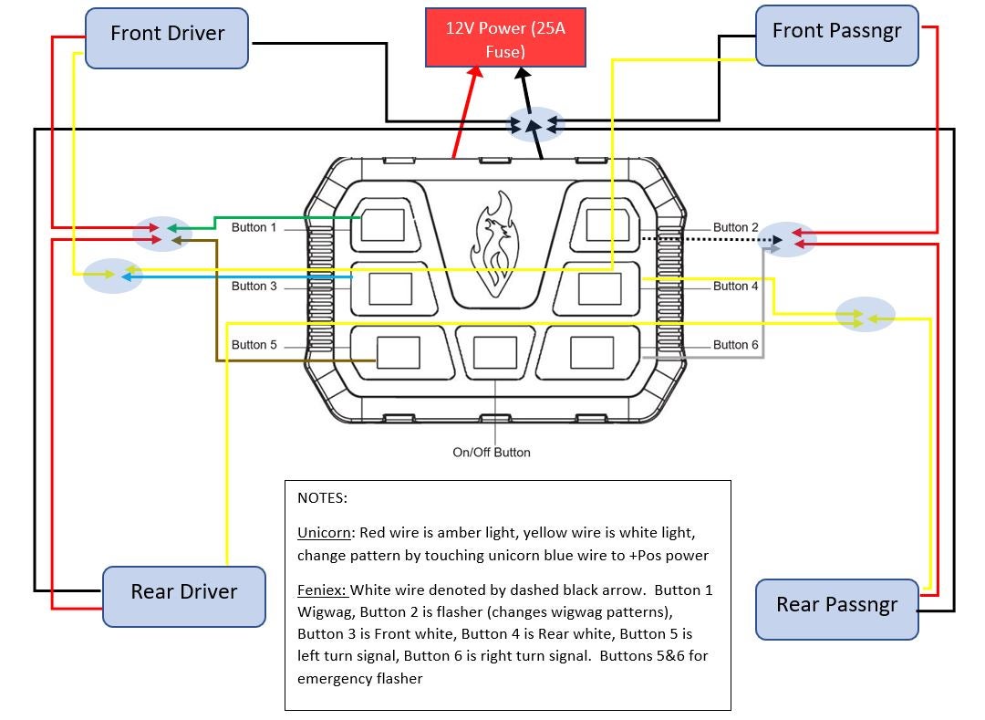
Feniex 4200 Mini Wiring Diagram is a schematic representation of electrical connections within Feniex 4200 Mini fire apparatus. It outlines the flow of electrical current through components such as the engine, alternator, battery, and lighting systems.
This diagram serves as a critical resource for technicians and electricians responsible for installing, maintaining, and troubleshooting electrical systems on Feniex 4200 Mini fire trucks. It enables them to diagnose and resolve electrical issues quickly and accurately, ensuring the safe and efficient operation of these essential emergency vehicles.
The development of comprehensive wiring diagrams has significantly improved the safety and reliability of fire apparatus. They provide a systematic approach to electrical system design and maintenance, reducing the risk of electrical fires, component failures, and operational disruptions. Understanding and utilizing wiring diagrams are fundamental skills for professionals in the fire service and related industries.
Understanding the essential aspects of a Feniex 4200 Mini Wiring Diagram is crucial for ensuring the safe and efficient operation of Feniex 4200 Mini fire apparatus. These diagrams provide a comprehensive overview of the electrical system, enabling technicians and electricians to diagnose and resolve issues quickly and accurately.
- Circuit Identification: Wiring diagrams clearly identify each electrical circuit, making it easier to trace and troubleshoot specific issues.
- Component Location: Diagrams show the physical location of electrical components, simplifying inspection and maintenance.
- Wire Color Coding: Wiring diagrams use color coding to differentiate between different types of wires, facilitating quick identification during installation and repair.
- Fuse and Relay Locations: Diagrams indicate the location of fuses and relays, enabling technicians to quickly identify and replace faulty components.
- Grounding Points: Wiring diagrams show the grounding points for the electrical system, ensuring proper grounding and reducing the risk of electrical shock.
- Connector Types: Diagrams identify the types of connectors used in the electrical system, allowing technicians to select the appropriate tools for making repairs.
- Wire Gauge and Length: Wiring diagrams specify the gauge and length of wires used in each circuit, ensuring proper current carrying capacity and minimizing voltage drop.
- Voltage and Current Ratings: Diagrams indicate the voltage and current ratings for each component, helping technicians select appropriate replacement parts.
- Testing Points: Wiring diagrams often include testing points for measuring voltage, current, and resistance, facilitating electrical diagnostics.
- Compliance with Codes and Standards: Wiring diagrams ensure that the electrical system meets applicable codes and standards, promoting safety and reliability.
These aspects of Feniex 4200 Mini Wiring Diagrams are essential for ensuring the proper installation, maintenance, and repair of fire apparatus electrical systems. By understanding and utilizing these diagrams, technicians can maintain the highest levels of safety and performance for these critical vehicles.
Circuit Identification
Within the context of “Feniex 4200 Mini Wiring Diagram,” circuit identification plays a pivotal role in ensuring the efficient and reliable operation of fire apparatus electrical systems. By clearly identifying each electrical circuit, wiring diagrams empower technicians and electricians with the ability to quickly trace and troubleshoot specific issues, minimizing downtime and maximizing the safety and performance of these critical vehicles.
- Circuit Labeling and Numbering: Wiring diagrams assign unique labels or numbers to each electrical circuit, enabling technicians to easily identify and differentiate between them. This systematic approach simplifies circuit tracing and fault isolation, reducing the time and effort required for troubleshooting.
- Color Coding: Wiring diagrams employ color coding to distinguish between different types of circuits, such as power, lighting, and communication circuits. This visual cue allows technicians to quickly identify the function of each circuit, facilitating faster and more accurate troubleshooting.
- Circuit Grouping: Wiring diagrams often group related circuits together, such as all lighting circuits or all engine control circuits. This logical organization aids in understanding the overall system design and simplifies troubleshooting by allowing technicians to focus on specific areas of the electrical system.
- Testing Points: Wiring diagrams may include designated testing points for each circuit, providing technicians with convenient access to measure voltage, current, and resistance. This feature facilitates quick and accurate electrical diagnostics, enabling technicians to pinpoint faults and identify the root cause of issues.
In summary, the circuit identification aspect of “Feniex 4200 Mini Wiring Diagram” is essential for efficient troubleshooting and maintenance of fire apparatus electrical systems. By clearly identifying each electrical circuit, wiring diagrams empower technicians with the ability to quickly trace and resolve issues, ensuring the safety, reliability, and performance of these critical vehicles.
Component Location
Within the context of “Feniex 4200 Mini Wiring Diagram,” the precise identification of component location plays a critical role in ensuring the efficient inspection and maintenance of fire apparatus electrical systems. Wiring diagrams serve as indispensable tools in this regard, providing technicians with a clear visual representation of the physical layout of electrical components.
By indicating the exact location of each component, wiring diagrams enable technicians to quickly and easily identify and access specific components for inspection, testing, or replacement. This expedited process minimizes downtime and maximizes the efficiency of maintenance procedures, ensuring that fire apparatus electrical systems remain in optimal operating condition.
For instance, if a technician needs to replace a faulty relay, the wiring diagram will provide the precise location of that relay within the electrical system. This information allows the technician to quickly locate and access the relay, reducing the time and effort required for the repair.
Furthermore, the accurate depiction of component location in wiring diagrams facilitates proactive maintenance practices. Technicians can use wiring diagrams to plan and schedule inspections and maintenance tasks based on the specific location and accessibility of components. This proactive approach helps prevent unexpected failures and ensures the long-term reliability of fire apparatus electrical systems.
In summary, the “Component Location: Diagrams show the physical location of electrical components, simplifying inspection and maintenance” aspect of “Feniex 4200 Mini Wiring Diagram” is a critical component for maintaining the safety, efficiency, and reliability of fire apparatus electrical systems. By providing technicians with precise information on component location, wiring diagrams streamline inspection and maintenance procedures, enabling technicians to quickly identify and address issues, minimize downtime, and ensure the optimal performance of these critical vehicles.
Wire Color Coding
Within the context of “Feniex 4200 Mini Wiring Diagram,” wire color coding plays an essential role in ensuring efficient and accurate installation and repair of fire apparatus electrical systems. Wiring diagrams utilize a standardized color coding scheme to differentiate between different types of wires, enabling technicians to quickly identify and trace wires, reducing errors and minimizing downtime.
- Power Wires: Power wires, which carry electrical current from the battery to various components, are typically color-coded red or black. This consistent color coding allows technicians to easily identify and trace power wires, ensuring proper connections and preventing electrical hazards.
- Ground Wires: Ground wires, which provide a path for electrical current to return to the negative terminal of the battery, are typically color-coded green or white. This color coding helps technicians quickly identify and connect ground wires, ensuring proper grounding and reducing the risk of electrical shocks.
- Signal Wires: Signal wires, which transmit control signals between different components, are often color-coded in a variety of colors, such as blue, yellow, or orange. This color coding scheme allows technicians to easily differentiate between different signal wires, facilitating troubleshooting and repair.
- Special Purpose Wires: Some wiring diagrams may also include special purpose wires, such as ignition wires or CAN bus wires, which are color-coded according to industry standards or manufacturer specifications. This color coding ensures that special purpose wires are properly identified and connected, preventing errors and maintaining system integrity.
By utilizing a standardized wire color coding scheme, “Feniex 4200 Mini Wiring Diagram” empowers technicians with the ability to quickly and accurately install and repair fire apparatus electrical systems. This color coding reduces the risk of errors, minimizes downtime, and enhances the overall safety and reliability of these critical vehicles.
Fuse and Relay Locations
Within the comprehensive framework of “Feniex 4200 Mini Wiring Diagram,” the precise identification of fuse and relay locations plays a crucial role in ensuring the efficient maintenance and repair of fire apparatus electrical systems. These diagrams serve as indispensable tools in this regard, providing technicians with a clear visual representation of the physical placement of fuses and relays throughout the electrical system.
- Expeditious Fault Isolation: Fuse and relay locations in wiring diagrams allow technicians to quickly identify and isolate faulty components. By indicating the exact placement of each fuse and relay, wiring diagrams expedite the troubleshooting process, minimizing downtime and maximizing the efficiency of maintenance procedures.
- Enhanced Safety: Accurate fuse and relay locations in wiring diagrams promote electrical safety by enabling technicians to quickly identify and replace blown fuses or faulty relays. This proactive approach prevents potential electrical hazards, ensuring the safe operation of fire apparatus electrical systems.
- Simplified System Upgrades: Wiring diagrams that clearly depict fuse and relay locations facilitate system upgrades and modifications. Technicians can easily identify the appropriate fuses and relays to add or replace, ensuring that electrical system modifications are performed safely and efficiently.
- Comprehensive Troubleshooting: Fuse and relay locations in wiring diagrams provide a comprehensive view of the electrical system, enabling technicians to perform thorough troubleshooting. By understanding the location and function of each fuse and relay, technicians can systematically diagnose and resolve electrical issues, ensuring the optimal performance of fire apparatus electrical systems.
In summary, the “Fuse and Relay Locations: Diagrams indicate the location of fuses and relays, enabling technicians to quickly identify and replace faulty components” aspect of “Feniex 4200 Mini Wiring Diagram” is a critical component for maintaining the safety, efficiency, and reliability of fire apparatus electrical systems. By providing technicians with precise information on fuse and relay locations, wiring diagrams streamline troubleshooting and repair procedures, enabling technicians to quickly identify and address issues, minimize downtime, and ensure the optimal performance of these critical vehicles.
Grounding Points
Within the context of “Feniex 4200 Mini Wiring Diagram,” grounding points play a critical role in ensuring the safety and reliability of fire apparatus electrical systems. Wiring diagrams depict the precise location of grounding points throughout the electrical system, enabling technicians to establish proper grounding connections and minimize the risk of electrical shock.
Electrical grounding provides a low-resistance path for electrical current to return to the negative terminal of the battery. This path is essential for ensuring the safe operation of electrical systems by preventing voltage surges and reducing the risk of electrical shocks. Wiring diagrams provide technicians with the information necessary to establish proper grounding connections by indicating the location of grounding points on the vehicle’s chassis, engine, and other components.
For instance, in the “Feniex 4200 Mini Wiring Diagram,” the grounding point for the electrical system may be located on the vehicle’s chassis near the battery. By connecting the negative terminal of the battery to this grounding point, technicians ensure that electrical current has a low-resistance path to return to the battery, reducing the risk of electrical shocks and ensuring the proper operation of the electrical system.
Furthermore, proper grounding is crucial for the effective operation of electrical components. Without proper grounding, electrical components may not function correctly or may experience premature failure. Wiring diagrams provide technicians with the information necessary to establish proper grounding connections, ensuring the optimal performance and longevity of electrical components.
In summary, the “Grounding Points: Wiring diagrams show the grounding points for the electrical system, ensuring proper grounding and reducing the risk of electrical shock” aspect of “Feniex 4200 Mini Wiring Diagram” is a critical component for maintaining the safety, reliability, and performance of fire apparatus electrical systems. By providing technicians with precise information on grounding point locations, wiring diagrams enable technicians to establish proper grounding connections, minimize the risk of electrical shock, and ensure the optimal operation of electrical components.
Connector Types
Within the context of “Feniex 4200 Mini Wiring Diagram,” the precise identification of connector types plays a crucial role in ensuring efficient and reliable repairs of fire apparatus electrical systems. Wiring diagrams serve as indispensable tools in this regard, providing technicians with a clear visual representation of the types of connectors used throughout the electrical system.
By indicating the specific types of connectors used at each connection point, wiring diagrams enable technicians to select the appropriate tools and techniques for making repairs. This information is critical for ensuring proper electrical connections, preventing damage to components, and maintaining the integrity of the electrical system.
For instance, in the “Feniex 4200 Mini Wiring Diagram,” a specific connector type may be used for connecting the engine control module to the wiring harness. By identifying the type of connector used, technicians can select the appropriate crimping tool or connector removal tool, ensuring a secure and reliable connection.
Furthermore, the identification of connector types in wiring diagrams facilitates troubleshooting and diagnostics. By understanding the types of connectors used in the system, technicians can quickly identify potential issues related to loose connections or damaged connectors.
In summary, the “Connector Types: Diagrams identify the types of connectors used in the electrical system, allowing technicians to select the appropriate tools for making repairs” aspect of “Feniex 4200 Mini Wiring Diagram” is a critical component for maintaining the safety, reliability, and performance of fire apparatus electrical systems. By providing technicians with precise information on connector types, wiring diagrams enable technicians to make efficient and reliable repairs, minimize downtime, and ensure the optimal performance of these critical vehicles.
Wire Gauge and Length
Within the context of “Feniex 4200 Mini Wiring Diagram,” the precise specification of wire gauge and length plays a critical role in ensuring the efficient and reliable operation of fire apparatus electrical systems. Wiring diagrams serve as indispensable tools in this regard, providing technicians with detailed information on the gauge and length of wires used in each circuit.
- Current Carrying Capacity: Wiring diagrams specify the gauge of wires used in each circuit, ensuring that the wires can safely carry the required amount of electrical current. By selecting the appropriate wire gauge, technicians can prevent overheating, voltage drop, and potential electrical hazards.
- Voltage Drop Minimization: Wiring diagrams also specify the length of wires used in each circuit, ensuring that voltage drop is minimized. Voltage drop occurs when electrical current flows through a wire, causing a reduction in voltage at the end of the wire. By specifying the optimal wire length, technicians can minimize voltage drop and ensure that electrical components receive the required voltage to operate properly.
- Circuit Protection: The gauge and length of wires used in each circuit also impact the effectiveness of circuit protection devices, such as fuses and circuit breakers. Wiring diagrams provide technicians with the information necessary to select the appropriate circuit protection devices for each circuit, ensuring that electrical faults are safely interrupted.
- System Reliability: Proper wire gauge and length selection contribute to the overall reliability of the electrical system. By specifying the optimal wire gauge and length, wiring diagrams help prevent premature wire failure, reduce the risk of electrical faults, and ensure the long-term reliability of fire apparatus electrical systems.
In summary, the “Wire Gauge and Length: Wiring diagrams specify the gauge and length of wires used in each circuit, ensuring proper current carrying capacity and minimizing voltage drop” aspect of “Feniex 4200 Mini Wiring Diagram” is critical for maintaining the safety, reliability, and performance of fire apparatus electrical systems. By providing technicians with precise information on wire gauge and length, wiring diagrams enable technicians to design and maintain electrical systems that meet the specific requirements of fire apparatus, ensuring the optimal performance of these critical vehicles.
Voltage and Current Ratings
Within the comprehensive framework of “Feniex 4200 Mini Wiring Diagram”, the precise specification of voltage and current ratings for each component plays a critical role in ensuring the safe and reliable operation of fire apparatus electrical systems. These ratings provide crucial information to technicians, enabling them to select appropriate replacement parts and maintain the integrity of the electrical system.
- Component Compatibility: Wiring diagrams specify the voltage and current ratings for each component, ensuring compatibility between the component and the electrical system. By selecting replacement parts with matching voltage and current ratings, technicians can prevent damage to components and ensure the proper functioning of the electrical system.
- Electrical Safety: Voltage and current ratings are essential for maintaining electrical safety. Wiring diagrams provide technicians with the information necessary to select replacement parts that meet the electrical safety requirements of the fire apparatus. This helps prevent electrical fires, shocks, and other hazards.
- System Performance: The voltage and current ratings of components impact the overall performance of the electrical system. Wiring diagrams enable technicians to select replacement parts that meet the performance requirements of the system, ensuring that electrical components operate efficiently and deliver the required power.
- Compliance with Standards: Wiring diagrams adhere to industry standards and regulations, ensuring that the voltage and current ratings of components comply with applicable codes. This compliance helps prevent electrical system failures and ensures the safe and reliable operation of fire apparatus.
In summary, the “Voltage and Current Ratings: Diagrams indicate the voltage and current ratings for each component, helping technicians select appropriate replacement parts” aspect of “Feniex 4200 Mini Wiring Diagram” is critical for maintaining the safety, reliability, and performance of fire apparatus electrical systems. By providing technicians with precise information on voltage and current ratings, wiring diagrams empower them to select compatible and safe replacement parts, ensuring the optimal functioning of these critical vehicles.
Testing Points
Within the comprehensive framework of “Feniex 4200 Mini Wiring Diagram”, the incorporation of testing points plays a crucial role in enabling efficient electrical diagnostics and troubleshooting. These testing points provide dedicated access points for technicians to measure voltage, current, and resistance, facilitating the identification and resolution of electrical issues.
- Convenient Measurement: Testing points are strategically placed throughout the electrical system, providing convenient access for technicians to take measurements without the need to disconnect or splice wires. This simplifies the diagnostic process and reduces the risk of introducing additional faults.
- Accurate Readings: Testing points are designed to provide accurate and reliable readings, ensuring that technicians can make informed decisions based on the measured values. This accuracy is critical for proper fault identification and effective troubleshooting.
- Circuit Analysis: By measuring voltage, current, and resistance at specific testing points, technicians can analyze the behavior of individual circuits and components. This information helps them identify open circuits, short circuits, or other electrical faults that may affect the performance of the fire apparatus.
- Component Testing: Testing points also facilitate the testing of individual components, such as sensors, actuators, and modules. By measuring the electrical signals at the testing points, technicians can assess the functionality of these components and identify potential issues.
In summary, the “Testing Points: Wiring diagrams often include testing points for measuring voltage, current, and resistance, facilitating electrical diagnostics” aspect of “Feniex 4200 Mini Wiring Diagram” empowers technicians with the tools necessary to perform efficient and accurate electrical diagnostics. These testing points provide convenient access, ensure accurate readings, facilitate circuit analysis, and enable component testing, ultimately contributing to the safe and reliable operation of Feniex 4200 Mini fire apparatus.
Compliance with Codes and Standards
Within the realm of “Feniex 4200 Mini Wiring Diagram,” compliance with codes and standards is a paramount consideration that underpins the safety and reliability of the electrical system. Wiring diagrams play a pivotal role in ensuring that the electrical system adheres to these established guidelines, safeguarding against potential hazards and promoting optimal performance.
- National Electrical Code (NEC) and Local Amendments: Wiring diagrams must comply with the National Electrical Code (NEC) and any local amendments or regulations. These codes provide comprehensive guidelines for the design, installation, and maintenance of electrical systems, ensuring the safety of personnel and property.
- Fire Apparatus Specific Standards: In addition to the NEC, fire apparatus electrical systems must also comply with specific standards developed by organizations such as the National Fire Protection Association (NFPA). These standards address the unique requirements and hazards associated with fire apparatus, ensuring that the electrical system can withstand the rigors of firefighting operations.
- Manufacturer Specifications: Wiring diagrams must adhere to the specifications set forth by the manufacturer of the fire apparatus. These specifications provide detailed instructions on the proper installation and maintenance of the electrical system, ensuring compatibility and optimal performance.
- Quality Assurance and Inspection: Compliance with codes and standards is often verified through quality assurance processes and inspections by qualified personnel. These inspections ensure that the electrical system meets the required specifications and operates safely and reliably.
By adhering to codes and standards, wiring diagrams contribute to the overall safety and reliability of Feniex 4200 Mini fire apparatus. They provide a roadmap for proper electrical system design, installation, and maintenance, minimizing the risk of electrical fires, shocks, and other hazards. Compliance with codes and standards is essential for ensuring that fire apparatus electrical systems perform optimally, supporting the critical mission of firefighting and emergency response.


Related Posts


