An Earphone Jack Wiring Diagram outlines the pin configurations and connection schema for audio jacks used in earphones, headphones, and other audio devices. It provides a visual representation of the wiring layout, with each pin labeled and identified according to its specific function.
Earphone Jack Wiring Diagrams are essential for proper audio signal transmission between audio sources and output devices. They ensure correct connectivity and prevent audio distortion or malfunction. These diagrams are referenced during the manufacturing and repair of audio equipment, enabling technicians to identify and wire jacks accurately.
In the realm of audio engineering, wiring diagrams play a crucial role. They serve as a universal language, facilitating communication between engineers, manufacturers, and service personnel. With the advent of digital audio, these diagrams have evolved to encompass both analog and digital connections, further enhancing their significance in the field.
Earphone Jack Wiring Diagrams, as technical schematics, play a multifaceted role in the design, manufacture, and maintenance of audio devices. Understanding their key aspects is crucial for comprehending their significance and application.
- Pin Configuration: Diagrams illustrate the arrangement and purpose of each pin within an earphone jack, ensuring proper signal transmission.
- Signal Routing: They depict the path of audio signals through the jack, enabling engineers to optimize signal flow and minimize interference.
- Connector Types: Diagrams identify the specific type of earphone jack being used, such as 3.5mm TRS or 2.5mm TRRS, ensuring compatibility with different devices.
- Grounding: Earphone Jack Wiring Diagrams indicate proper grounding techniques to prevent noise and distortion, ensuring clear audio transmission.
- Shielding: Diagrams specify shielding methods to protect audio signals from electromagnetic interference, maintaining signal integrity.
- Insulation: They outline insulation materials and techniques used to prevent short circuits and ensure electrical safety.
- Soldering: Diagrams provide guidance on soldering techniques for secure and reliable connections, ensuring optimal audio performance.
- Testing: They include guidelines for testing the functionality and performance of earphone jacks, ensuring they meet industry standards.
- Troubleshooting: Diagrams assist in diagnosing and resolving audio issues related to earphone jacks, minimizing downtime and maximizing user satisfaction.
These key aspects collectively contribute to the effective design, implementation, and maintenance of Earphone Jack Wiring Diagrams, ensuring reliable and high-quality audio transmission in various electronic devices.
Pin Configuration
Pin configuration is a critical component of Earphone Jack Wiring Diagrams, as it determines the arrangement and purpose of each pin within the jack. Proper pin configuration ensures that audio signals are transmitted correctly between audio sources and output devices, preventing distortion, noise, and malfunction.
In an Earphone Jack Wiring Diagram, each pin is labeled and identified according to its specific function. This includes pins for left and right audio channels, ground, and sometimes microphone or other control signals. The diagram specifies the order and position of these pins within the jack, ensuring that they align correctly with the corresponding pins on the mating connector.
Real-world examples of pin configuration in Earphone Jack Wiring Diagrams include:
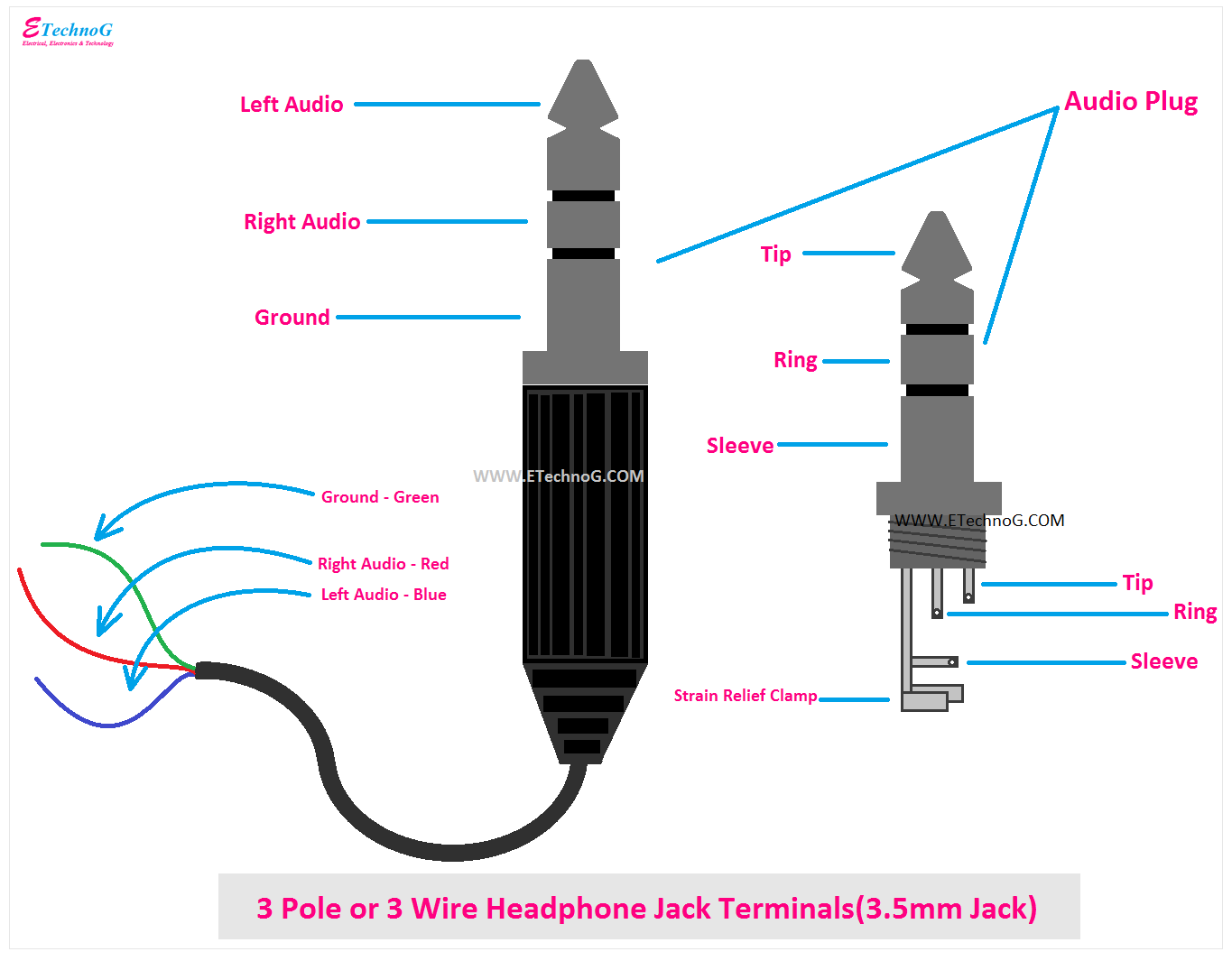
- 3.5mm TRS connector: This common connector type features three pins arranged in a tip-ring-sleeve (TRS) configuration. The tip carries the left audio channel, the ring carries the right audio channel, and the sleeve is ground.
- 2.5mm TRRS connector: This connector type adds an extra pin to the TRS configuration, allowing for the transmission of microphone signals. The additional pin is located between the ring and sleeve contacts.
- 4-pole XLR connector: This professional audio connector type features four pins, with two pins for balanced audio signals, one pin for ground, and one pin for phantom power.
Understanding pin configuration is essential for designing, manufacturing, and maintaining audio devices. It enables engineers to ensure that audio signals are routed correctly, protecting against electrical shorts, noise, and other issues that can degrade audio quality.
Signal Routing
Signal routing plays a pivotal role in Earphone Jack Wiring Diagrams. It illustrates the path of audio signals as they travel through the jack, allowing engineers to arrange the internal circuitry optimally. This optimization minimizes signal loss, distortion, and interference, ensuring high-quality audio transmission.
Real-life examples of signal routing in Earphone Jack Wiring Diagrams include:
- Stereo headphone jack: This diagram depicts the routing of left and right audio signals through separate channels, ensuring accurate stereo reproduction.
- Microphone-enabled headset jack: This diagram includes an additional signal path for microphone input, enabling hands-free communication.
- Balanced audio jack: This diagram shows the use of balanced signal routing to reduce noise and improve signal integrity in professional audio applications.
Understanding signal routing is crucial for designing high-performance audio devices. It enables engineers to minimize signal degradation, optimize sound quality, and ensure compatibility with various audio equipment.
In conclusion, signal routing is a critical component of Earphone Jack Wiring Diagrams, providing a visual representation of the audio signal’s path through the jack. This understanding helps engineers optimize signal flow, minimize interference, and design high-quality audio devices.
Connector Types
Earphone Jack Wiring Diagrams play a crucial role in ensuring compatibility between audio devices by specifying the type of earphone jack used. The connector type determines the physical dimensions, pin configuration, and signal routing within the jack, ensuring a proper fit and optimal audio transmission.
- Jack Dimensions: Diagrams specify the physical dimensions of the earphone jack, including its diameter and length. This information is essential for ensuring that the jack fits securely into the corresponding port on the audio device.
- Pin Configuration: Diagrams identify the arrangement and purpose of each pin within the earphone jack, as discussed in the previous section. This information is crucial for ensuring proper signal transmission and preventing damage to the audio device.
- Signal Compatibility: Diagrams indicate the type of audio signals that the earphone jack can transmit. This includes specifications for analog or digital signals, as well as the number of channels (mono or stereo).
- Microphone Support: Diagrams specify whether the earphone jack supports microphone input. This information is important for headsets that require both audio output and microphone capabilities.
Understanding connector types is essential for designing and manufacturing audio devices that are compatible with a wide range of headphones, earphones, and other audio accessories. By adhering to standard wiring diagrams and connector specifications, manufacturers can ensure seamless audio connectivity and enhance the user experience.
Grounding
Grounding is a critical component of Earphone Jack Wiring Diagrams, as it ensures that all electrical components are connected to a common reference point, preventing noise and distortion in the audio signal. Without proper grounding, audio signals can become corrupted by electrical interference, resulting in audible noise, hum, or crackling sounds.
Earphone Jack Wiring Diagrams specify the proper grounding techniques for each type of jack, ensuring that the ground connection is established and maintained throughout the entire audio path. This involves connecting the ground pin of the jack to the chassis or ground plane of the audio device, providing a low-resistance path for electrical current to flow.
Real-life examples of grounding in Earphone Jack Wiring Diagrams include:
- In a 3.5mm TRS connector, the sleeve contact is designated as the ground connection.
- In a 2.5mm TRRS connector, the fourth contact is used for ground.
- In balanced audio connectors, such as XLR and TRS, the shield or pin 1 is typically used for grounding.
Understanding grounding techniques in Earphone Jack Wiring Diagrams is essential for designing and manufacturing high-quality audio devices. Proper grounding ensures that audio signals are transmitted cleanly and without interference, resulting in a more enjoyable listening experience for users.
Shielding
In the realm of Earphone Jack Wiring Diagrams, shielding plays a pivotal role in maintaining the integrity of audio signals. Shielding methods specified in these diagrams protect the delicate audio signals from electromagnetic interference (EMI), ensuring clear and distortion-free sound transmission.
- Grounding and Shielding: Diagrams indicate proper grounding techniques and shielding methods to minimize EMI. This includes connecting the ground pin of the jack to the chassis or ground plane of the device, as well as using shielded cables and connectors to prevent signal degradation.
- Connector Design: Shielding is incorporated into the design of earphone jacks themselves. Metal shells and conductive coatings help to shield the internal contacts from external interference, maintaining signal quality.
- Cable Shielding: Earphone Jack Wiring Diagrams specify the use of shielded cables to protect audio signals from EMI. These cables feature a conductive shield, typically made of braided copper or aluminum foil, which surrounds the inner conductor and prevents interference from external sources.
- EMI Suppression Components: Diagrams may also include EMI suppression components, such as capacitors and ferrite beads, to further reduce noise and interference. These components filter out unwanted signals and ensure that only the desired audio signal is transmitted.
Understanding shielding techniques in Earphone Jack Wiring Diagrams is crucial for designing and manufacturing audio devices that deliver pristine sound quality. Proper shielding ensures that audio signals remain free from noise and distortion, resulting in an immersive and enjoyable listening experience for users.
Insulation
In the context of Earphone Jack Wiring Diagrams, insulation plays a critical role in ensuring the safe and reliable operation of audio devices. It prevents short circuits and other electrical hazards by isolating electrical conductors and preventing current from flowing where it is not intended.
- Insulating Materials: Diagrams specify the types of insulating materials used, such as plastics, rubber, and enamel. These materials have high electrical resistance, preventing current from flowing through them.
- Insulation Thickness: The thickness of the insulation is also specified in the diagrams. Thicker insulation provides greater protection against electrical hazards, but it can also affect the flexibility and size of the jack.
- Soldering and Insulation Techniques: Diagrams provide guidance on proper soldering and insulation techniques to ensure that connections are secure and insulated. This prevents accidental shorts and ensures the longevity of the jack.
- Testing and Inspection: Diagrams may also include guidelines for testing and inspecting insulation to verify its integrity and ensure that it meets safety standards.
Understanding insulation in Earphone Jack Wiring Diagrams is essential for ensuring the safety and reliability of audio devices. Proper insulation prevents electrical hazards, protects users from injury, and extends the lifespan of the equipment.
Soldering
Within the context of Earphone Jack Wiring Diagrams, soldering is a crucial technique for establishing secure and reliable electrical connections. Diagrams provide detailed guidance on proper soldering methods, ensuring optimal audio performance and preventing potential issues.
- Soldering Materials: Diagrams specify the appropriate solder alloys and fluxes to use, depending on the materials being joined and the desired strength and conductivity of the connection.
- Soldering Techniques: Diagrams illustrate the correct soldering techniques, including the proper use of soldering irons, the application of solder, and the techniques for creating strong and durable solder joints.
- Quality Control: Diagrams may also include guidelines for inspecting and testing solder joints to ensure their integrity and compliance with industry standards.
- Troubleshooting: Diagrams can provide guidance on troubleshooting common soldering problems, such as cold solder joints, solder bridges, and component overheating.
Understanding and adhering to the soldering guidelines provided in Earphone Jack Wiring Diagrams is essential for ensuring the proper functioning and longevity of audio devices. Proper soldering techniques prevent intermittent connections, noise, and other audio issues, contributing to a seamless and enjoyable listening experience.
Testing
In the realm of “Earphone Jack Wiring Diagrams”, testing plays a crucial role in ensuring the proper operation and reliability of earphone jacks. These diagrams provide detailed guidelines for testing the functionality and performance of jacks, enabling manufacturers and technicians to verify their adherence to industry standards.
- Electrical Testing: Diagrams specify tests to verify the electrical characteristics of the jack, such as contact resistance, insulation resistance, and voltage withstand. These tests ensure that the jack meets electrical safety requirements and provides reliable signal transmission.
- Mechanical Testing: Diagrams outline mechanical tests to assess the durability and robustness of the jack. This includes testing for insertion and extraction forces, as well as resistance to vibration and shock. Mechanical testing helps ensure that the jack can withstand the rigors of everyday use.
- Acoustic Testing: Diagrams may include guidelines for acoustic testing to evaluate the audio performance of the jack. This involves testing for frequency response, distortion, and crosstalk. Acoustic testing helps ensure that the jack provides high-quality audio transmission without introducing unwanted noise or artifacts.
- Environmental Testing: Diagrams can incorporate tests to assess the jack’s performance under various environmental conditions, such as extreme temperatures, humidity, and dust. Environmental testing ensures that the jack can operate reliably in different environments.
Comprehensive testing based on Earphone Jack Wiring Diagrams is essential for ensuring the quality and reliability of audio devices. By adhering to these guidelines, manufacturers can produce jacks that meet industry standards, delivering optimal performance and a seamless user experience.
Troubleshooting
Troubleshooting plays a critical role within the context of Earphone Jack Wiring Diagrams, as it provides valuable guidance for diagnosing and resolving audio issues related to earphone jacks. By utilizing the information provided in these diagrams, technicians and users can quickly identify and address common problems, minimizing downtime and ensuring optimal audio performance.
Earphone Jack Wiring Diagrams serve as a comprehensive resource for troubleshooting, as they offer detailed schematics and instructions for testing and repairing earphone jacks. These diagrams illustrate the electrical connections within the jack, allowing technicians to pinpoint the source of audio issues and determine the appropriate corrective actions.
Real-life examples of troubleshooting using Earphone Jack Wiring Diagrams include:
- Diagnosing intermittent audio dropouts by checking for loose connections or damaged wires.
- Identifying short circuits by measuring continuity between contacts.
- Resolving audio distortion by ensuring proper grounding and shielding.
Understanding the principles of troubleshooting using Earphone Jack Wiring Diagrams is essential for maintaining high-quality audio performance in various devices. By leveraging these diagrams, users and technicians can effectively diagnose and resolve audio issues, ensuring a seamless and enjoyable listening experience.


Related Posts


