A Dyna 2000i Ignition Wiring Diagram is a schematic representation of the electrical connections required to install and operate a Dyna 2000i ignition system. It provides a visual guide to the wiring harness, coils, spark plugs, and other components, ensuring proper functionality and preventing electrical hazards.
The wiring diagram is crucial for both professional installers and DIY enthusiasts. It enables them to identify and troubleshoot electrical issues, optimize ignition timing, and ensure the engine runs smoothly and efficiently. For instance, it can be used to diagnose problems such as misfires, weak spark, or faulty connections.
The Dyna 2000i ignition system has been widely adopted in the automotive industry for its reliability, performance, and ease of installation. The wiring diagram has played a key role in its widespread adoption, simplifying the integration process and ensuring safe and efficient operation.
The Dyna 2000i Ignition Wiring Diagram is a multifaceted concept with several key aspects that are critical to understanding its significance. These aspects encompass its role, components, applications, benefits, and historical context, among others. Each aspect provides a unique perspective on the Dyna 2000i Ignition Wiring Diagram, contributing to its overall importance and relevance.
- Function: The Dyna 2000i Ignition Wiring Diagram serves as a visual guide for installing and operating the Dyna 2000i ignition system, ensuring proper electrical connections and optimizing engine performance.
- Components: It comprises symbols and lines representing the ignition system’s components, including the wiring harness, coils, spark plugs, sensors, and other electrical elements.
- Applications: The wiring diagram finds applications in various automotive and industrial settings where the Dyna 2000i ignition system is employed, such as in high-performance vehicles, racing engines, and industrial machinery.
- Benefits: It provides numerous benefits, including simplified installation, improved ignition timing, enhanced engine efficiency, and reduced maintenance costs.
- Historical Context: The Dyna 2000i Ignition Wiring Diagram has evolved over time, reflecting advancements in ignition technology and the increasing complexity of automotive electrical systems.
- Accuracy: Precise and accurate wiring diagrams are essential for ensuring the proper functioning and safety of the ignition system.
- Troubleshooting: The wiring diagram serves as a valuable tool for troubleshooting electrical issues and identifying faulty connections or components.
- Customization: It allows for customization of the ignition system to meet specific performance requirements or accommodate modifications.
- Safety: Adhering to the wiring diagram helps prevent electrical hazards, ensuring the safe operation of the ignition system.
- Industry Standards: The wiring diagram conforms to industry standards and best practices, ensuring compatibility and reliability.
In conclusion, the Dyna 2000i Ignition Wiring Diagram is a multifaceted concept that encompasses various key aspects, each contributing to its significance and relevance. Understanding these aspects provides a deeper appreciation of the role, applications, benefits, and historical context of the wiring diagram, enabling effective utilization and troubleshooting of the Dyna 2000i ignition system.
Function
The function of the Dyna 2000i Ignition Wiring Diagram is directly tied to the Dyna 2000i ignition system’s overall purpose and effectiveness. Without the wiring diagram, the ignition system cannot be correctly installed, and its components cannot communicate and function harmoniously.
The wiring diagram provides a comprehensive overview of the ignition system’s electrical connections, ensuring that each component receives the correct voltage and signals. This is critical for optimizing engine performance, as the ignition system is responsible for generating the spark that ignites the air-fuel mixture in the engine’s cylinders.
For instance, if the wiring diagram is not followed precisely, or if there is a fault in the wiring, it can lead to incorrect ignition timing, which can cause engine misfires, reduced power output, and increased fuel consumption. Additionally, faulty wiring can result in electrical shorts or even fires, posing safety hazards.
Therefore, the Dyna 2000i Ignition Wiring Diagram serves as a critical component of the Dyna 2000i ignition system, ensuring its proper installation, operation, and performance. Understanding the relationship between the wiring diagram and the ignition system is essential for technicians, installers, and enthusiasts alike.
Components
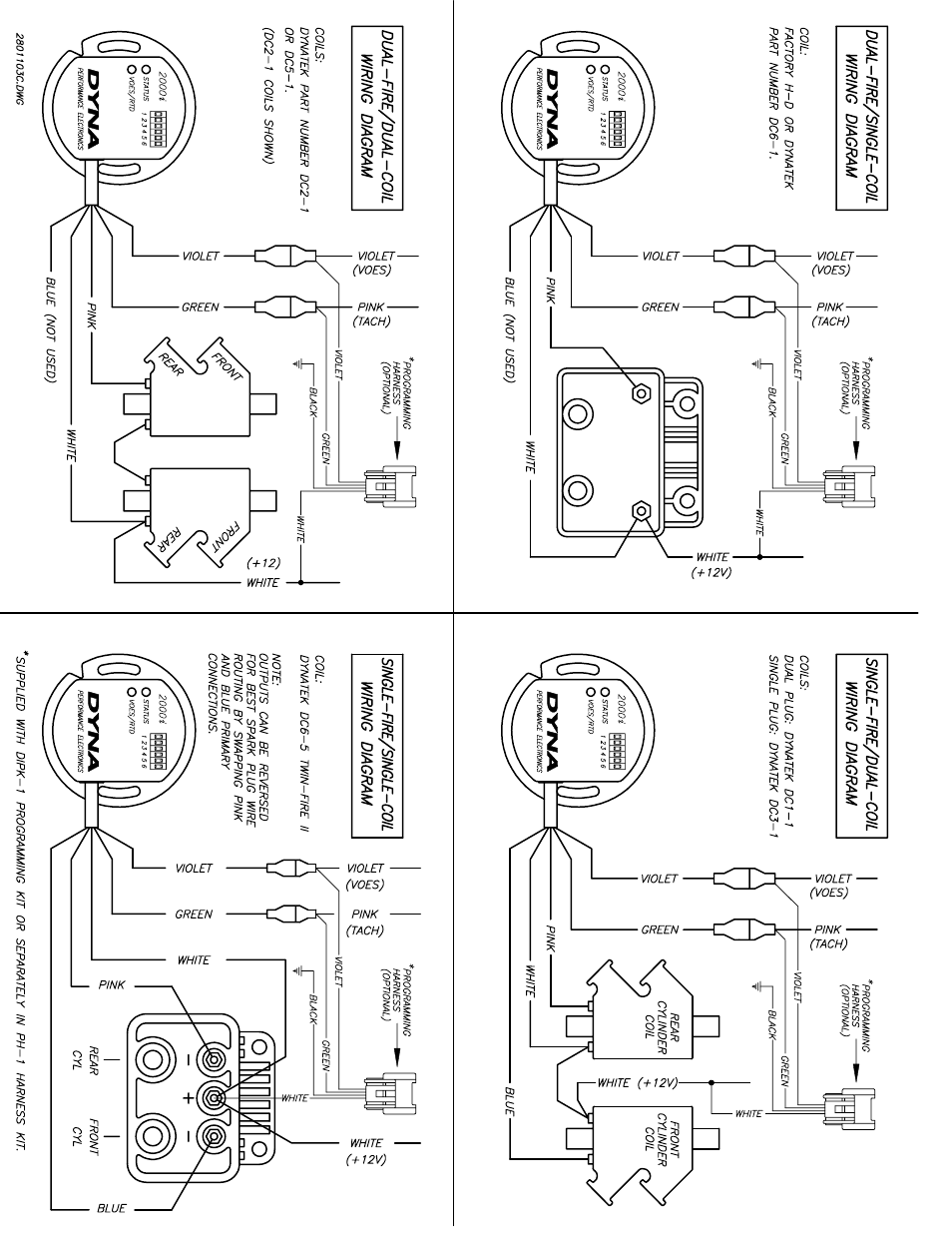
The Dyna 2000i Ignition Wiring Diagram is a visual representation of the electrical connections between the various components of the Dyna 2000i ignition system. These components include the wiring harness, coils, spark plugs, sensors, and other electrical elements. Each component plays a critical role in the proper functioning of the ignition system and is represented by a unique symbol on the wiring diagram.
For instance, the wiring harness is represented by a series of lines connecting the different components. The coils are represented by circles or squares, while the spark plugs are represented by small lightning bolts. Sensors are typically represented by triangles or squares with a wavy line inside, and other electrical elements, such as resistors and capacitors, are represented by their respective symbols.
The wiring diagram provides a clear and concise overview of the ignition system’s electrical connections, making it easier for technicians and enthusiasts to understand how the system works and troubleshoot any problems. It also serves as a valuable reference for installing and maintaining the ignition system.
In summary, the components of the Dyna 2000i ignition system are represented by symbols on the wiring diagram, providing a visual representation of the electrical connections between them. This allows technicians and enthusiasts to understand the system’s operation, troubleshoot problems, and ensure its proper installation and maintenance.
Applications
The Dyna 2000i Ignition Wiring Diagram plays a crucial role in ensuring the proper installation and operation of the Dyna 2000i ignition system across a wide range of applications. Its versatility and adaptability make it a valuable tool in various automotive and industrial settings.
- High-Performance Vehicles: In high-performance vehicles, the Dyna 2000i ignition system provides precise ignition timing and increased spark energy, leading to improved engine responsiveness, power output, and fuel efficiency. The wiring diagram helps ensure that the ignition system is correctly installed and configured to meet the specific requirements of high-performance engines.
- Racing Engines: The Dyna 2000i ignition system is widely used in racing engines, where reliability and precision are paramount. The wiring diagram enables racers and engine builders to tailor the ignition system to the unique characteristics of their engines, optimizing performance and durability under extreme operating conditions.
- Industrial Machinery: The Dyna 2000i ignition system finds applications in industrial machinery, such as generators, pumps, and compressors. The wiring diagram provides guidance for installing and maintaining the ignition system in these applications, ensuring reliable and efficient operation of the machinery.
- Marine Applications: In marine environments, the Dyna 2000i ignition system is employed in outboard and inboard engines. The wiring diagram assists in protecting the ignition system from moisture and corrosion, ensuring reliable engine operation even in challenging marine conditions.
In conclusion, the applications of the Dyna 2000i Ignition Wiring Diagram extend beyond the automotive industry, encompassing a wide range of high-performance, racing, industrial, and marine applications. Its versatility and reliability make it an indispensable tool for optimizing engine performance, reliability, and efficiency across diverse operating environments.
Benefits
The Dyna 2000i Ignition Wiring Diagram offers a multitude of benefits that contribute to the optimal performance and functionality of the Dyna 2000i ignition system. These benefits encompass simplified installation, enhanced ignition timing, improved engine efficiency, and reduced maintenance costs, each playing a vital role in maximizing engine performance and longevity.
-
Simplified Installation:
The wiring diagram provides clear and concise instructions, making the installation process straightforward and less time-consuming. This simplified installation process reduces the risk of errors and ensures proper system operation. -
Improved Ignition Timing:
Precise ignition timing is crucial for optimal engine performance. The wiring diagram ensures that the ignition system delivers the spark at the exact moment required, maximizing engine power and efficiency. Proper ignition timing also reduces harmful emissions and improves fuel economy. -
Enhanced Engine Efficiency:
The optimized ignition timing facilitated by the wiring diagram leads to more efficient combustion within the engine cylinders. This improved efficiency translates into increased power output, reduced fuel consumption, and lower operating costs. -
Reduced Maintenance Costs:
Proper installation and precise ignition timing contribute to the longevity and reliability of the ignition system. By minimizing wear and tear on components, the wiring diagram helps reduce maintenance costs and extends the lifespan of the ignition system.
In summary, the Dyna 2000i Ignition Wiring Diagram provides tangible benefits that enhance the performance, efficiency, and cost-effectiveness of the ignition system. These benefits underscore the importance of accurate wiring and precise ignition timing, ultimately contributing to optimal engine operation and reduced maintenance requirements.
Historical Context
The Dyna 2000i Ignition Wiring Diagram has not remained static over time but has undergone significant evolution, mirroring the advancements in ignition technology and the growing complexity of automotive electrical systems. This historical context provides valuable insights into the ongoing development of the Dyna 2000i ignition system and its adaptability to meet the demands of modern engines.
-
Component Evolution:
Over time, various components within the Dyna 2000i ignition system have been refined and improved. For instance, the introduction of electronic ignition modules replaced mechanical breaker points, leading to more precise ignition timing and reduced maintenance. -
Circuitry Enhancements:
The wiring diagram has also witnessed the integration of additional circuitry to accommodate new features and sensors. This includes the incorporation of knock sensors, oxygen sensors, and electronic throttle control, enabling the ignition system to optimize performance based on real-time engine operating conditions. -
ECU Integration:
The Dyna 2000i ignition system has become increasingly integrated with engine control units (ECUs). This integration allows for more sophisticated control over ignition timing, dwell time, and other parameters, resulting in improved engine efficiency and reduced emissions. -
Software Updates:
With the advent of programmable ignition systems, software updates have become an integral part of the historical context. These updates provide enhancements to the ignition timing maps, fuel injection strategies, and other operating parameters, optimizing the system for specific engine configurations and performance goals.
In conclusion, the Dyna 2000i Ignition Wiring Diagram has undergone continuous evolution, driven by advancements in ignition technology and the increasing complexity of automotive electrical systems. This historical context highlights the ongoing refinement and optimization of the ignition system, enabling it to meet the demands of modern engines and contribute to improved performance, efficiency, and emissions control.
Accuracy
The accuracy of the Dyna 2000i Ignition Wiring Diagram is of paramount importance for several reasons. Precise and accurate wiring diagrams are fundamental to ensuring the proper functioning and safety of the ignition system, as any errors or inaccuracies can lead to a range of issues.
Firstly, incorrect wiring can result in improper ignition timing, which can cause the engine to run poorly or even damage components. For instance, if the spark plugs are not firing at the correct time, the engine may experience misfires, reduced power, and increased fuel consumption. In severe cases, incorrect ignition timing can lead to engine damage, such as burnt valves or pistons.
Secondly, inaccurate wiring can lead to electrical shorts or fires. If wires are not properly connected or insulated, they can come into contact with each other or with other components, causing a short circuit. This can lead to a loss of power, damage to electrical components, or even a fire.
To prevent these issues, it is essential to ensure that the Dyna 2000i Ignition Wiring Diagram is accurate and up-to-date. This means using the correct wiring diagram for the specific model and year of the vehicle, and following the instructions carefully.
By understanding the critical connection between accuracy and the Dyna 2000i Ignition Wiring Diagram, technicians and enthusiasts can ensure the proper functioning and safety of the ignition system, leading to optimal engine performance and reliability.
Troubleshooting
Within the context of the Dyna 2000i Ignition Wiring Diagram, troubleshooting plays a pivotal role in ensuring proper system functioning and optimal engine performance. The wiring diagram serves as an invaluable tool for diagnosing and resolving electrical issues, enabling technicians and enthusiasts to pinpoint faulty connections or components accurately and efficiently.
-
Electrical Continuity Testing:
Using a multimeter, technicians can perform electrical continuity tests to check for proper current flow throughout the ignition system. The wiring diagram provides a clear roadmap of the electrical connections, allowing for systematic testing of wires, connectors, coils, and other components. -
Voltage and Resistance Measurements:
The wiring diagram facilitates voltage and resistance measurements at various points within the ignition system. By comparing measured values against specified ranges, technicians can identify potential issues such as voltage drops, excessive resistance, or open circuits. -
Component Isolation:
The wiring diagram enables the isolation of individual components within the ignition system for testing. By temporarily disconnecting a component and observing the system’s behavior, technicians can determine whether that component is causing the issue. -
ECU Code Interpretation:
Modern ignition systems often integrate with engine control units (ECUs) that store diagnostic trouble codes (DTCs) when issues are detected. The wiring diagram provides valuable information for interpreting these DTCs and identifying the root cause of the problem.
In conclusion, the Dyna 2000i Ignition Wiring Diagram empowers technicians and enthusiasts with the ability to troubleshoot electrical issues and identify faulty connections or components effectively. This facilitates timely repairs, prevents further system damage, and ensures optimal engine performance and reliability.
Customization
Within the realm of the Dyna 2000i Ignition Wiring Diagram, customization emerges as a crucial aspect, enabling the ignition system to adapt to diverse performance demands and accommodate modifications. This flexibility empowers users to tailor the ignition system to their unique requirements, optimizing engine operation and achieving desired outcomes.
-
Coil Selection:
The wiring diagram provides insights into the compatibility of various ignition coils, allowing users to select coils with specific characteristics. This customization allows for optimization of spark energy, dwell time, and ignition timing, catering to specific engine modifications or performance goals. -
Timing Adjustments:
The wiring diagram facilitates adjustments to ignition timing, enabling users to fine-tune the timing curve to suit different engine configurations or fuel types. This customization optimizes combustion efficiency, reduces emissions, and enhances overall engine responsiveness. -
Rev Limiter Settings:
The wiring diagram provides guidance on adjusting the rev limiter, which sets the maximum engine speed. Customization of the rev limiter allows users to protect the engine from over-revving, ensuring reliability and longevity, especially in high-performance applications. -
External Input Integration:
The wiring diagram enables the integration of external inputs, such as boost controllers or nitrous oxide systems. This customization allows users to integrate additional performance-enhancing components, maximizing power output and tailoring the ignition system to specific racing or performance requirements.
In summary, the customization capabilities outlined in the Dyna 2000i Ignition Wiring Diagram empower users to adapt the ignition system to their specific needs and preferences. Whether optimizing ignition timing, selecting appropriate coils, adjusting rev limits, or integrating external inputs, the wiring diagram provides the necessary guidance to achieve desired performance outcomes and ensure compatibility with various modifications.
Safety
The Dyna 2000i Ignition Wiring Diagram plays a critical role in ensuring the safe operation of the ignition system. By providing a clear and accurate roadmap of the electrical connections, it guides users in installing, maintaining, and troubleshooting the system, minimizing the risk of electrical hazards.
Electrical hazards can arise from various factors, including incorrect wiring, loose connections, and faulty components. If the wiring diagram is not followed precisely, or if there is a fault in the wiring, it can lead to short circuits, electrical fires, or even personal injury. The wiring diagram helps prevent these hazards by providing detailed instructions and visual representations of the proper electrical connections.
For instance, the wiring diagram specifies the correct wire gauges and types to be used for different components, ensuring that the wires can handle the electrical load without overheating or causing a fire. It also indicates the proper polarity of connections, preventing damage to sensitive electronic components.
Furthermore, the wiring diagram assists in troubleshooting electrical issues, enabling users to identify faulty connections or components quickly and safely. By following the diagram, users can isolate the problem area and take appropriate corrective actions, reducing the risk of further damage or hazards.
In summary, adhering to the Dyna 2000i Ignition Wiring Diagram is essential for ensuring the safe operation of the ignition system. By providing a clear and accurate guide to electrical connections, it helps prevent electrical hazards, protects against damage to components, and ensures the safety of users.
Industry Standards
Within the realm of the Dyna 2000i Ignition Wiring Diagram, industry standards play a pivotal role in ensuring compatibility, reliability, and optimal performance. Adherence to industry standards guarantees that the wiring diagram aligns with established norms and best practices within the automotive and electrical engineering domains.
-
Component Compatibility:
Industry standards define the specifications and dimensions of electrical components, ensuring compatibility between different manufacturers. By conforming to these standards, the Dyna 2000i Ignition Wiring Diagram facilitates the seamless integration of ignition system components, regardless of their source.
-
Safe and Reliable Operation:
Industry standards incorporate safety guidelines and best practices to minimize electrical hazards and ensure reliable operation. The Dyna 2000i Ignition Wiring Diagram adheres to these standards, specifying proper wire gauges, insulation materials, and connection methods to prevent short circuits, fires, and other electrical issues.
-
Performance Optimization:
Industry standards often include recommendations for optimal performance and efficiency. The Dyna 2000i Ignition Wiring Diagram incorporates these recommendations, providing guidance on wire routing, grounding techniques, and component placement to minimize electrical interference and maximize ignition system performance.
-
Simplified Troubleshooting:
Conforming to industry standards promotes consistency in wiring diagrams across different ignition systems. This consistency simplifies troubleshooting and repair processes, as technicians can leverage their knowledge and experience with other systems to identify and resolve issues more efficiently.
In conclusion, the Dyna 2000i Ignition Wiring Diagram’s adherence to industry standards ensures compatibility, reliability, performance optimization, and simplified troubleshooting. By following established norms and best practices, the wiring diagram facilitates the seamless integration, safe operation, and optimal performance of the ignition system.


![[DIAGRAM] Dyna 2000i Installation Diagram](https://i0.wp.com/img.jpcycles.com/zoom/380-623_A_V1.jpg?w=665&ssl=1)


Related Posts


